Table of Contents
Advertisement
Quick Links
Advertisement
Table of Contents

Related Manuals for Omron ZN-CTX21


Summary of Contents for Omron ZN-CTX21
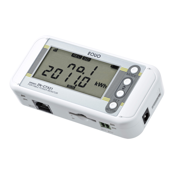
- Page 1 EQUO Series Portable Power Monitor ZN-CTX21 User’s Manual ASC-DE-111020-8C...
- Page 2 Describes package content items and detailed procedures for assembly, setting operation, recording operation and data display Product specifications Other necessary information required to use the Portable Power Monitor ZN-CTX21 Station Utility User's Manual Describes the information of accessory, functions and operation of the PC software Station...
- Page 3 THE PRODUCTS, WHETHER SUCH CLAIM IS BASED ON CONTRACT, WARRANTY, NEGLIGENCE, OR STRICT LIABILITY. In no event shall the responsibility of OMRON for any act exceed the individual price of the product on which liability is asserted. IN NO EVENT SHALL OMRON BE RESPONSIBLE FOR WARRANTY, REPAIR, OR OTHER...
- Page 4 Application Considerations <SUITABILITY FOR USE> OMRON shall not be responsible for conformity with any standards, codes, or regulations that apply to the combination of the products in the customer's application or use of the products. At the customer's request, OMRON will provide applicable third party certification documents identifying ratings and limitations of use that apply to the products.
- Page 5 Precautions on Safety Meanings of Signal Words ● For the safe operation of ZN-CTX21, this operation manual indicates the precautions by using the following marks and symbols. The precautions given here contain important information related to safety, and therefore must be observed.
- Page 6 CAUTION A minor or moderate injury or property damage may occur due to explosion. Do not use the product in an environment containing an inflammable or explosive gas. An electric shock may occur. Do not replace the batteries when the unit is clamped to a conductor for measurement.
- Page 7 ・ The product cannot be used for measurement of the secondary circuit of an inverter. ・ Take anti-static electricity measures (e.g. touching grounded metal object) when handling the product. ・ Only the dedicated CT specified by OMRON must be used. Dedicated CT: ZN-CT-A...
- Page 8 ・ Do not install batteries in wrong polarities. ・ Always attach the battery cover during use. OMRON cannot be responsible for the product performance, if the batteries accidentally drop off the product due to the unattached battery cover.
- Page 9 ・ Remove the batteries when they are not used for a long time. ・ Used batteries remaining installed for a long time may leak and corrode in the product. ・ Do not disassemble or throw the battery into the fire. ・...
-
Page 10: How To Read This Manual
・ How to Read This Manual Symbols Used in this Manual ■ Menu items that are displayed on the screen, windows, dialog boxes and other GUI elements displayed on the PC are indicated by brackets "[ ]". Marks Used in this Manual ■... -
Page 11: Table Of Contents
Table of Contents Introduction ..............................i Table of Contents ............................x Product Overview ..........................1-1 Features and Functions....................... 1-1 Portable Power Monitor for Easy Operation at Manufacturing Sites ........1-1 Network Connection ......................1-1 Recording to an SD Memory Card ..................1-1 Graph Display and Data Processing Software .............. - Page 12 3.4.1 Overview..........................3-6 Setting Tool .......................... 3-6 Logging Tool ........................3-6 Momentary Value Display (SD Viewer ES)................3-6 Integration and Summation Tool (Energy Viewer) ..............3-6 3.4.2 Installation..........................3-6 Setting the Measurement Conditions ................... 3-7 Switching to "FUN" Mode ..................... 3-7 Setting the Number of Channels to Use (USECH) (Example: 2 Channels) ......
- Page 13 (22) Time Setting (CLOCK) ....................... 4-16 (23) YEAR/MONTH/DAY/TIME Setting ..................4-17 (24) Network Setting (NET) ....................... 4-17 (25) Setting IP Address (IP) ....................... 4-17 (26) IP Address and Subnet Mask (IP 1 to IP 4, SUB 1 to SUB 4) ..........4-18 (27) DTAIL ..........................
-
Page 14: Product Overview
Features and Functions Portable Power Monitor for Easy Operation at Manufacturing Sites The ZN-CTX21 Portable Power Monitor provides simplified wiring operation and measurement of power consumption (converted values) without stopping lines. Power data acquisition at operation sites now becomes easy, contributing to enhanced energy-saving efficiency. -
Page 15: Alarm Output
1. Product Overview Alarm Output Alarm output terminals are provided on the Portable Power Monitor. The alarm is output when the integrated power value exceeds the upper limit. This feature provides 'visualization' of the power limit, allowing the operator to quickly handle problems. (Available in the NORM and HISPD measurement operation modes) Backup Batteries This product provides an uninterruptible power supply consisting of two AAA batteries, which... -
Page 16: Configuration
1. Product Overview Configuration This product can be used in the following two types of configuration. LAN Cable Network Connection Standalone 1.2.1 Standalone Portable Power Monitors can be operated standalone without connecting them to a network. The measured data is recorded in the internal memory and can be loaded to a PC via an SD card. -
Page 17: Easy Power Measurement
1. Product Overview Easy Power Measurement The Portable Power Monitor displays the measured momentary power during the power is ON. The monitor measures electric current values, which are then multiplied by a specified voltage and power factor (the ratio of effective power) to convert them into power values. A long press of the SET/REC/STOP key measures and displays an integrated power ... -
Page 18: Setup And Operation Procedure
1. Product Overview Setup and Operation Procedure 1.4.1 Standalone Operation Check the package contents ⇒3.1 Checking the Package Contents Check the required items ⇒3.2 Preparing the Required Items Connect the sensor head, alarm output terminals and prepare the power supply ⇒3.3 Configuring the Unit Install the Station Utility PC software ⇒"Station Utility User's Manual": 1. -
Page 19: Operation Via Network
1. Product Overview 1.4.2 Operation via Network Check the package contents ⇒3.1 Checking the Package Contents Check the required items ⇒3.2 Preparing the Required Items Connect the sensor head, alarm output terminals and prepare the power supply ⇒3.3 Configuring the Unit Install the Station Utility PC software ⇒"Station Utility User's Manual": 1. -
Page 20: Part Name And Function
2. Part Name and Function Part Name and Function MODE Key △ Key Display Unit ▽ Key Sensor Head Connector LAN Port AC Adapter Terminal SD Card Slot Alarm Output Terminals SET/REC/STOP Key Screw Hook Hole Battery Cover Mounting Screw Hole Reset Switch Display Unit Display Unit... - Page 21 2. Part Name and Function Indicator Definition Display Definition/Function (When Displayed) An Integral power consumption reset interval is set. The setting is OFF when this is not displayed. Communication via LAN cable is in process. A LAN cable is connected and network communication is ready. Data is being recorded in the internal memory.
-
Page 22: Control Unit
2. Part Name and Function Control Unit 2.2.1 Control Key Name Function Switches the operation mode. MODE Key Resets an alarm or error (Long press). Cancels the setting before applying it. Moves the setting items (Upward). Item Selection Switches the display. (△... -
Page 23: Inserting Sd Card
2. Part Name and Function Inserting SD Card 「SD」点灯 "SD" turns ON (1) Insert an SD card into the SD card slot with the metal terminal facing up. (2) Push the card inward until it clicks. Click! (3) “SD” appears on the display. Removing SD Card (1) Push the inserted SD card inward until it clicks. -
Page 24: Input/Output Specifications
2. Part Name and Function Input/Output Specifications 2.3.1 Alarm Output Alarm Output Terminals (1) OUT Outputs the judgment result allocated in THR mode. (2) GND It is a common terminal. The terminal names are inscribed on the unit. Use the provided alarm output connector for wiring. Output Specifications Important ・Do not connect the external power supply directly between OUT and GND. -
Page 25: Check And Preparation
3. Check and Preparation Check and Preparation Checking the Package Contents This product package includes the following items: □Main Unit ZN-CTX21 □AC Adapter or DC cable □Alarm Output Connector □Instruction Sheet □Startup Guide □Mounting Magnet (Pre-installed) Preparing the Required Items The following items are required to use this product. -
Page 26: Configuring The Unit
3. Check and Preparation Configuring the Unit 3.3.1 Connecting Dedicated CT The separately sold dedicated CT of ZN-CT□□1-□A or ZN-CTM-A CT is required to use this product. Click! Insert the dedicated CT in the sensor head connector until it clicks. Important A branch cable (ZN-CTM11-C) is required when using ZN-CTM-A. -
Page 27: Preparing Power Supply
3. Check and Preparation 3.3.3 Preparing Power Supply An external power supply or batteries can supply power to this product. Connecting to External Power Supply (1) Insert the AC adapter or DC cable plug into the power supply terminal on the unit. (2) Connect the AC plug of the AC adapter to an outlet (100 VAC to 240 VAC) when using AC power supply. -
Page 28: Using Batteries
3. Check and Preparation Using Batteries (1) Slide the battery cover off the rear side of the unit. (2) Mount two batteries to the correct polarities in the battery compartment. (3) Slide the battery cover on to close the battery compartment. -
Page 29: Checking Operation
3. Check and Preparation 3.3.4 Checking Operation After the power is turned ON, the type name and version are displayed for a while. Then, the power information appears on the display. Press ▽ or △ keys to change the display while the "RUN" indicator at the bottom of the display is ON. -
Page 30: Station Utility Pc Software Overview And Preparation
3. Check and Preparation Station Utility PC Software Overview and Preparation 3.4.1 Overview Station Utility PC software consists of four principal functions. Refer to "Station Utility User's Manual" for details. Setting Tool This function provides remote operations including measurement condition settings (except for some settings), recording start and stop on the PC for remotely located Portable Power Monitors. -
Page 31: Setting The Measurement Conditions
3. Check and Preparation Setting the Measurement Conditions Set the measurement conditions for the object to measure. The measurement conditions include six items: the number of channels to use (USECH), the measurement target circuit (TYPE), the dedicated CT type (CT), the voltage of the measurement target (VOLT), power factor (PF) and frequency (FREQ). -
Page 32: Setting Measurement Target Circuit (Type) And Dedicated Ct Type (Ct)
3. Check and Preparation Setting Measurement Target Circuit (TYPE) and Dedicated CT Type (CT) Set the measurement target circuit (TYPE) and dedicated CT type (CT) in the same way as the previous setting. Refer to the FUN mode description for the measurement target circuit and dedicated CT type details. -
Page 33: Connecting To Network
・Connection to an in-house network or an existing LAN requires caution, since specific restrictions or rules may have been applied to the IP address management. Consult your network administrator. In case that such a network is used, however, OMRON cannot guarantee the performance of the Portable Power Monitors and the PC software. -
Page 34: Setting Portable Power Monitor Ip Address
3. Check and Preparation and must not overlap one another in the network. In the example above, Portable Power Monitor Unit 2 is assigned with "192.168.0.21", the PC, "192.168.0.100", changing the fourth value (segment) of the IP address of the monitor Unit 1, in order to distinguish among the units connected. -
Page 35: Setting Etc And Ip To "Disp
3. Check and Preparation Setting ETC and IP to “DISP” Display Operation (Upper/Lower) Press the ▽ or △ key until "ETC" appears at the upper row on CLEAR the display. ("FUN" Blinking) ↓ ▽or △ Key Press the SET/REC/STOP key. "OFF" at the lower row starts blinking. -
Page 36: Changing Ip Address (From Factory Default: 192.168.0.20 To 192.168.0.21)
3. Check and Preparation Changing IP Address (from factory default: 192.168.0.20 to 192.168.0.21) Display Operation (Upper/Lower) Display the first segment of the IP address. Press the ▽ or △ key until "P 1" appears at the upper row. DISP ↓ ▽or △... -
Page 37: Setting The Pc Ip Address
3. Check and Preparation 3.6.3 Setting the PC IP Address This section describes the procedure to change the IP address of the PC to "192.168.0.100". Login with a user account with administrator/manager authority, which is required to change the IP address of the PC. Windows XP Follow the procedure below to set the IP address. - Page 38 3. Check and Preparation (2) Click “Network Connections”. (3) Right-click “Local Area Connection” and select “Properties”. 3-14...
- Page 39 3. Check and Preparation (4) Highlight “Internet Protocol (TCP/IP)” and click “Properties”. (5) Select “Use the following IP address” and set “IP address” to "192.168.0.100" and “Subnet mask” to "255.255.255.0". Press “OK” to close the window. (6) Click "OK" in the “Local Area Connection Properties” window. The window closes. 3-15...
-
Page 40: Windows Vista
3. Check and Preparation Windows Vista Follow the procedure below to set the IP address. (1) Select “Start menu” – “Control Panel” and click “Network and Internet”. (2) Click “Network and Sharing Center”. 3-16... - Page 41 3. Check and Preparation (3) Click “Manage network connections”. (4) Right-click “Local Area Connection” and select “Properties”. (5) When the “User Account Control” window appears, click “Continue”. 3-17...
- Page 42 3. Check and Preparation (6) Select “Internet Protocol Version 4 (TCP/IPv4)” and click “Properties”. (7) Select “Use the following IP address” and set “IP address” and “Subnet mask”. Click “OK” to close the window. (8) Click "Close" in the “Local Area Connections Properties” window. The window closes. 3-18...
-
Page 43: Windows 7
3. Check and Preparation Windows 7 Follow the procedure below to set the IP address. (1) Select “Start menu” – “Control Panel” and click “Network and Internet”. (2) Click “Network and Sharing Center”. 3-19... - Page 44 3. Check and Preparation (3) Click “Change adapter settings”. (4) Right-click “Local Area Connection” and select “Properties”. 3-20...
- Page 45 3. Check and Preparation (5) Select “Internet Protocol Version 4 (TCP/IPv4)” and click “Properties”. (6) Select “Use the following IP address” and set “IP address” and “Subnet mask”. Click “OK” to close the window. (7) Click "Close" in the “Local Area Connections Properties” window. The window closes. 3-21...
-
Page 46: Connecting Lan Cable
3. Check and Preparation 3.6.4 Connecting LAN Cable Use LAN cables to connect the Portable Power Monitor units and the PC to the network. When the LAN cables have been properly connected, the "LAN" indicator turns ON on the unit display. "LAN"... -
Page 47: Mounting The Unit
3. Check and Preparation Mounting the Unit This section describes the procedure to install a Portable Power Monitor unit. Important This product is a sensitive device. Take caution not to let it drop when installing. Use screws to fix the product through the provided mounting screw holes for installation on the wall or other equipment where vibration or shock may directly affect the unit. -
Page 48: Securing With Mounting Screws
3. Check and Preparation 3.7.3 Securing with Mounting Screws Mounting screw holes are provided on the rear side of the unit, which are attached with mounting magnets by default. The unit can be screw-mounted through the holes by removing the magnets. (Refer to the Appendix: Installation Diagram for the screw hole dimensions.) Flat-head Screws: M3 x 6 Mounting Magnets Important... -
Page 49: Attaching Dedicated Ct To Measurement Target
3. Check and Preparation Attaching Dedicated CT to Measurement Target Attach the dedicated CT on the wire to the measurement target. When using a Clamp-on CT (ZN-CT51A), refer to the instruction sheet of the Clamp-on (1) Align the sides of the dedicated CT to the power supply side (K) and load side (L) correctly. - Page 50 3. Check and Preparation <Single-phase Three-wire> <Three-phase Three-wire> Power Supply Side (K) Power Supply Side (K) Branching/Fixing Hook Load Side (L) Load Side (L) If the number of channels is "3CH", clamp CH1 at phase R, CH2 at phase S and CH3 at phase T.
-
Page 51: Setting The Unit (Unit Operation)
4. Setting the Unit (Unit Operation) Setting the Unit (Unit Operation) Setting Procedure and Operation Modes The following diagram shows the Portable Power Monitor setting procedure flow: MODE Key RUN Mode FUN Mode THR Mode MODE Key MODE Key Twice △/▽... -
Page 52: Settings (Fun Mode Operation)
4. Setting the Unit (Unit Operation) Settings (FUN Mode Operation) Enter FUN mode to make measurement and recording settings on the Portable Power Monitor. 4.2.1 Setting Item List The following list shows the setting items available in FUN mode. Factory Display Item Display Setting Item... - Page 53 4. Setting the Unit (Unit Operation) When set to 1CH: 1P2 (Single-phase, two-wire) / 3P3 (Three-phase, three-wire) When set to 2CH: 1P3 (Single-phase, three-wire) / 3P3 (Three-phase, three-wire) When set to 3CH: 3P4 (Three-phase, four-wire) Dedicated CT 5A/50A/100A/200A 100A type Voltage of 1.0 to 9999.9 VOLT...
- Page 54 4. Setting the Unit (Unit Operation) Measurement RANGE NORM/AUTO AUTO range Rate/CO RATE conversion 00.000 to 99.999 value setting JPY/USD/EUR/CNY/ CONV Conversion unit KRW/CO restoration REREC OFF/ON availability at startup...
-
Page 55: Selecting "Fun" Operation Mode
4. Setting the Unit (Unit Operation) 4.2.2 Selecting "FUN" Operation Mode Press the MODE key to change the operation mode to "FUN". The "FUN" indication on the right of the display starts blinking. MODE Key RUN Mode THR Mode FUN Mode MODE Key MODE Key Twice... -
Page 56: Selecting Items
4. Setting the Unit (Unit Operation) 4.2.3 Selecting Items Move the selection items using the △ and ▽ keys. To change the set value, select the item with △ or ▽ key and apply the selection with the SET/REC/STOP key. Press the MODE key to change the operation mode. -
Page 57: Definition Of Items
4. Setting the Unit (Unit Operation) 4.2.4 Definition of Items Ranking Clear (CLEAR) Clears the ranking. (The ranking is also cleared when the power is turned OFF.) Operation: A press of the REC key displays "CLEAR" at the lower row on the display. If the REC key is pressed again (when the "CLEAR"... -
Page 58: Timer Setting (Timer)
4. Setting the Unit (Unit Operation) 10 seconds Approx. 25 days 20 seconds Approx. 29 days 30 seconds Approx. 30 days 1 minute Approx. 32 days * The table above only shows representative values. The actual battery life depends on the measurement environment, recording interval, measurement mode as well as the type and performance of the SD memory card and batteries to use. -
Page 59: Start Time (Stime)
4. Setting the Unit (Unit Operation) Start Time (STIME) Specifies the recording start time. Recording starts at a specified time every day. Setting range (Numeric input): 00:00 to 23:59 Initial value: 00:00 Note ・STIME cannot be specified when STRIG is set to "OFF". Important ・Recording continues if recording has been already in progress when the specified start time is reached. -
Page 60: End Time (Etime)
4. Setting the Unit (Unit Operation) End Time (ETIME) Specifies the recording end time. Recording stops at a specified time every day. The range of selection (Numeric input): 00:00 to 23:59 Initial value: 00:00 Note ・ETIME cannot be specified when ETRIG is set to "OFF" or "ELPSD". ・Recording stops when the specified end time is reached overriding a record start command via key operation or communication. -
Page 61: Measurement Mode (Mode)
4. Setting the Unit (Unit Operation) Measurement Mode (MODE) Used to select the measurement mode (e.g. SLEEP mode). The range of selection (Options): NORM / SLEEP / HISPD Initial value: SLEEP Measurement Mode Operation NORM The unit provides normal operation. SLEEP Sleep mode The unit provides energy saving operation. -
Page 62: Recording Mode (Rec)
4. Setting the Unit (Unit Operation) (10) Recording Mode (REC) Specifies the write operation to the SD memory card during recording. The range of selection (Options): CONT / RING Initial value: CONT Recording Mode Operation CONT Continue mode The unit outputs the files in the internal memory to the SD memory card when the internal memory becomes full during recording, and continues recording. -
Page 63: The Number Of Channels To Use (Usech)
4. Setting the Unit (Unit Operation) (12) The Number of Channels to Use (USECH) Specifies the number of channels to use. The same number of dedicated CTs must be set. The range of selection (Options): 1CH / 2CH / 3CH Initial value: 1CH (13) Measurement Target Circuit (TYPE) -
Page 64: Power Factor (Pf)
4. Setting the Unit (Unit Operation) (16) Power Factor (PF) Specifies the power factor of the circuit to be measured. The power factor refers to the ratio of the real power to the apparent power in the circuit. The power factor varies depending on the measurement target;... -
Page 65: Others (Etc)
4. Setting the Unit (Unit Operation) (19) Others (ETC) Specifies if the unit displays the items for setting file read/write, time setting, and network setting. Setting range: OFF / DISP Initial value: OFF Setting Value Operation The unit does not display the items for setting data read/write, time setting, network setting, DTAIL, rate/CO2 conversion value setting and conversion unit setting. -
Page 66: Writing The Setting Data (Bckup)
4. Setting the Unit (Unit Operation) (21) Writing the Setting Data (BCKUP) Saves the unit setting data in an SD memory card as a backup. Operation: Insert an SD memory card and hold the SET/REC/STOP key. Saving is complete when “DONE” is displayed. Important Only one setting data item (the setting data for only one unit) can be stored in a single SD card as a backup. -
Page 67: Year/Month/Day/Time Setting
4. Setting the Unit (Unit Operation) (23) YEAR/MONTH/DAY/TIME Setting Specifies the year/month/day/time values. Setting range (Numeric input): YEAR: 2000 to 2099 MONTH:1 to 12 DAY: 1 to 31 TIME: 00:00 to 23:59 Note The year/month/day/time settings are not possible when ETC is set to "OFF" and CLOCK is also set to "OFF". -
Page 68: Ip Address And Subnet Mask (Ip 1 To Ip 4, Sub 1 To Sub 4)
4. Setting the Unit (Unit Operation) (26) IP Address and Subnet Mask (IP 1 to IP 4, SUB 1 to SUB 4) Specifies the 4 segments of the IP address (IP 1 to IP 4) and the 4 segments of the subnet mask (SUB 1 to SUB 4). -
Page 69: Zero-Out Low Current Value (Locut)
4. Setting the Unit (Unit Operation) Note The rated primary side current value cannot be specified when ETC is set to "OFF" and DTAIL is also set to "OFF". (29) Zero-out Low Current Value (LOCUT) Determines low current values to be zeroed out by specifying the threshold value in a percentage to the dedicated CT type (CT) current value. -
Page 70: Rate/Co 2 Conversion Value Setting (Rate)
4. Setting the Unit (Unit Operation) (31) Rate/CO Conversion Value Setting (RATE) Specifies the electricity rate or CO emission level per 1kWh. The range of selection (Numeric input): 00.000 to 99.999 Initial value: 0.000 Note The rate/CO conversion value setting is not possible when ETC is set to "OFF". (32) Conversion Unit Setting (CONV) Specifies the unit for the rate/CO... -
Page 71: Changing The Set Value
4. Setting the Unit (Unit Operation) 4.2.5 Changing the Set Value The value setting depends on the type of items, which are classified into option selection type and numeric input type. Changing Option Type Item Values (Example: CYCLE) Press the MODE key several times to enter FUN mode, and press the ▽ or △ key to display CYCLE. -
Page 72: Changing Numeric Input Type Item Value (Example: Year)
4. Setting the Unit (Unit Operation) Changing Numeric Input Type Item Value (Example: YEAR) Press the MODE key several times to enter FUN mode, and press the ▽ or △ key to display YEAR. To display YEAR, ETC and TIME must have been set to DISP beforehand. Display Operation (Upper/Lower) -
Page 73: Settings (Thr Mode Operation)
4. Setting the Unit (Unit Operation) Settings (THR Mode Operation) THR mode must be entered for setting the threshold for Portable Power Monitor alarm output. Set the upper limit of the integrated power consumption for the threshold value. If the measured value exceeds the set upper limit value during RUN operation, the station's alarm output terminal turns ON and the "ALM"... -
Page 74: Selecting "Thr" Operation Mode
4. Setting the Unit (Unit Operation) 4.3.2 Selecting "THR" Operation Mode Press the MODE key to change the operation mode to "THR". "THR" at the lower right of the display starts blinking. MODE Key THR Mode RUN Mode FUN Mode MODE Key MODE Key Twice... -
Page 75: Definition Of Items
4. Setting the Unit (Unit Operation) 4.3.4 Definition of Items Upper Limit Threshold of kWh or Higher Integrated Power (INT H) Specifies the integrated power consumption upper limit threshold for an alarm output. The "ALM" indication and alarm output turn ON, when the measured integrated power exceeds the set value. -
Page 76: Measurement And Recording (Unit Operation)
5. Measurement and Recording (Unit Operation) Measurement and Recording (Unit Operation) Overview Measured values can be recorded in two ways: recording in Portable Power Monitor units or in the PC via network. This chapter explains recording in Portable Power Monitor units. Selecting Operation Mode RUN mode must be entered for power measurement. -
Page 77: Screen Transition In Run Mode
5. Measurement and Recording (Unit Operation) Screen Transition in RUN Mode Pressing the △ or ▽ key in RUN mode switches the display as shown below. Pressing the MODE key changes the operation mode. Momentary Power Upper: No display. Lower: Displays the momentary power (kW). Individual CH Momentary Current Upper: "CHx"... - Page 78 5. Measurement and Recording (Unit Operation) Rate/CO Conversion Value Unit Upper: Displays the rate/CO conversion value. Lower: Shows the unit of the rate/CO conversion value. Ranking Integrated Power The unit shows the integrated power ranking from the highest to lowest value for individual intervals specified by the INTEG setting.
- Page 79 5. Measurement and Recording (Unit Operation) Number of Recorded Data Items Current Time Upper: Displays the number of recorded data items Lower: Displays the current time. Returns to the first display. Note ・The "REC" indication turns ON during data recording. ・"ALM"...
-
Page 80: Starting/Stopping Recording
5. Measurement and Recording (Unit Operation) Starting/Stopping Recording 5.4.1 Starting Recording The unit starts recording power level when the SET/REC/STOP key is held (long press for at least 3 seconds) in RUN mode or when the specified start time is reached. The "REC" indication turns ON when recording starts. -
Page 81: Sd Outputting File To Sd Memory Card
5. Measurement and Recording (Unit Operation) internal memory is written to the SD memory card. The data is discarded once the unit starts recording. SD Outputting File to SD Memory Card Recorded data can be output to SD memory card files when any of the following cases happen. - Page 82 5. Measurement and Recording (Unit Operation) the function assigned to that key, press it again when the display has recovered from SLEEP mode. Refer to: 4.2.4 (3) Measurement Mode (MODE)
-
Page 83: Ratings And Performance
6. Ratings and Performance Ratings and Performance Item Description Connectable Sensor ZN-CTS□1-□A, ZN-CTM□1-□A Display 7-seg. 5-digit 2-step LCD display, auxiliary information indicator displays Recording Interval 1 s, 2 s, 5 s, 10 s, 20 s, 30 s, 1 min. Operation Function Momentary power, Integrated power consumption Measurement Normal mode, Sleep mode*... - Page 84 *6: Output when the integrated power upper limit specified in THR mode is exceeded. An alarm output is not available in SLEEP mode. *7: An OMRON HMC-SD291 SD Memory Card or an SDHC Class 4 or higher memory card is recommended.
-
Page 85: Appendix
Hold the MODE key for 3 seconds or more to cancel the error display. There may be a failure on the hardware. Please contact HARD the distributor or OMRON representative office. The Hardware error E**** displayed error code is required for identifying the problem. -
Page 86: Character Display List
Appendix Character Display List Display String Display String Display String Main Messages Appendix- 2... -
Page 87: Sd Memory Card Folder Structure
Appendix SD Memory Card Folder Structure Root Folder _FARM System Folder SYSTEM System Folder [Serial Number] Recorded Data Folder [Year-Month-Day] Recorded (20000101.001 to Data [年月日] 20991231.999) (CSV File) File/Folder Name Description For system use. _FARM Do not modify the file names or the internal files. For system use. -
Page 88: Calibration
Appendix Calibration Portable Power Monitor units do not required calibration. Appendix- 4... -
Page 89: Installation Diagram
Appendix Installation Diagram Screw Hook Installation Dimension Screw Hook Holes Mounting Screw Mounting Screw Holes: 2-M3; Depth: 4 mm Installation Dimension (Unit: mm) Appendix- 5... -
Page 90: Revision History6-0
Revision History The specifications of this product are subject to changes without prior notice due to the addition of new functions or modification for improvement. These changes will be reflected in relevant manuals whenever such changes are made. The revised manual contains the revision history with the manual revision codes and the revision descriptions. - Page 91 ASC-DE-111020-8C...
Need help?
Do you have a question about the ZN-CTX21 and is the answer not in the manual?
Questions and answers