Table of Contents
Advertisement
Quick Links
Advertisement
Table of Contents

Subscribe to Our Youtube Channel
Related Manuals for Omron AX-OP05-E


Summary of Contents for Omron AX-OP05-E
- Page 1 Cat. No. Ixxx-Ex-xx-X DRAFT V0.90 LCD 5 LINE DIGITAL OPERATOR USER’S MANUAL...
-
Page 2: Table Of Contents
LCD Digital Operator Table of Contents 1. Introduction............................4 1.1 Main Features ..........................4 1.2 Unpacking and Inspection......................4 2. Name of parts and contents ......................5 2.1 Operation Key ..........................6 2.2 LCD display ........................... 7 2.3 Connection, wiring, and attaching ....................8 3. - Page 3 LCD Digital Operator Thank you for purchasing LCD digital operator. This instruction manual is written about how to use LCD digital operator. You could use this manual for inspection, maintenance, setting and use it with the main body of inverter. After reading this manual, keep it handy for future reference. SAFETY To get best performance with LCD digital operator, read this manual and all of the warning sign attached to the inverter carefully before installation and operation, and follow the instruction exactly.
-
Page 4: Introduction
LCD Digital Operator 1. Introduction 1.1 Main Features LCD digital operator features state-of-the-art components and functions to provide user-friendly interface. LCD digital operator can connect to MX2, RX and LX inverters and has 5-line display that shows parameters by function code and by name. This allows you to operate the inverter remotely, via a cable. -
Page 5: Name Of Parts And Contents
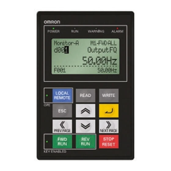
LCD Digital Operator 2. Name of parts and contents 2. RUN LED 3. WARNING LED 1. POWER LED 4. ALARM LED 7. LCD display 8. OPERATION 5. REMOTE LED 6. KEY ENABLED LED Name of parts Color Contents Power Led Green Light on when power is supplied to the LCD digital operator. -
Page 6: Operation Key
LCD Digital Operator 2.1. Operation Key Key image Key Name Function It changes from Local to Remote mode. Press the key during 2 seconds to change from Local to Remote or REMOTE Remote to Local. When it is in Local the OPE led will be ON. -
Page 7: Lcd Display
LCD Digital Operator 2.2. LCD Display Backlight There are two backlight colors in the LCD display, white and orange. They reflect the state of the inverter as follows: Contents Backlight Color White Normal (It is not related to inverter driving/stop) Orange Warning (Parameter mismatch) White ↔... -
Page 8: Connection, Wiring, And Attaching
LCD Digital Operator 2.3 Connection, wiring, and attaching Please process the control panel as shown, and fix from the other side with M3 screw (5mm) when you install the operator on the control panel. Recommended torque is [0.9, 1.0] Nm. 26.5 2-Φ4 2-M3x5 (Backside) -
Page 9: Operation
LCD Digital Operator 3. Operation 3.1 Changing Display Modes LCD digital operator has four display modes which can be changed from one to another by pressing the key at Navigation level. Moreover, there are 3 other modes called Read mode, Write mode and Option mode. In any display mode, it moves to Read mode or Write mode via key or key, and moves to Option mode after pressing at the same... -
Page 10: Option Mode
LCD Digital Operator 3.2 Option Mode 1- Please press key at the same time to enter into the OPTION MODE. The cursor will appear in the first row of the Option Mode menu. Use key to move between the option Mode menu. To return to the navigation layer, press the key. -
Page 11: Details Of Option Mode
LCD Digital Operator 3.3 Details of Option mode Item Content Setting range Default 01: English 02: Deutsch 03: Français 04: Español 05: Italiano Language Setting language 06: Português 07: 日本語 (Japanese) 08: 中文 (Chinese) 09: Türkçe 10: PycckИЙ Date: 2000/1/1~2099/12/31 2009/01/01 Setting Date and Time for the LCD Date and Time... -
Page 12: Monitor-A Display Mode
LCD Digital Operator 3.4 Monitor-A Display Mode 1- Please select monitor mode A by using the key at the navigation layer. The cursor will be displayed in the Monitor-A pressing key. 2- After that, use the key to select the function code to be displayed into the Monitor-A. -
Page 13: Monitor-B Display Mode
LCD Digital Operator 3.5 Monitor–B Display Mode 1- Please select the Display Mode Monitor-B using the key at the navigation layer. 2- After pressing the key the cursor will appear on the first row of the four “d” group inverter parameters. Use the key to move between the four Monitor-B inverter parameters. -
Page 14: Function Mode
LCD Digital Operator 3.6 Function Mode 1- Please select Function Mode by using the key at the navigation level. 2- Pressing the key the cursor will appear in the function code. Then use the key to select the function that will be changed. 3- After that, pressing the key the cursor will appear in the parameter value. -
Page 15: Trip Mode
LCD Digital Operator 3.7 Trip Mode 1- Select the key to select trip mode at the navigation layer. 2- Pressing the key, the past trip information (6 trip errors) and the warning information (1 time), that are recorded on the inverter, will be displayed. -
Page 16: Read/Write Function And Operation
LCD Digital Operator 4. Read/Write function and operation LCD digital operator can read and save Inverter parameter settings, and copy them to another inverter. Specifically LCD digital operator can save four inverters’ parameter sets or one inverter’s parameter set and its EzSQ (Drive Programming) program. It can be selected via the R/W Storage Mode in the LCD configuration Option Mode. -
Page 17: R/W Storage Mode - Single Write Function
LCD Digital Operator 4.2 R/W Storage Mode - Single WRITE function After pressing the key in any display mode except Read mode and Option mode, the parameter settings stored in LCD digital operator are transferred to the inverter. If the inverter supports EzSQ (Drive Programming), it will be transferred to the inverter automatically after the parameter copy is finished. -
Page 18: R/W Storage Mode - Quad Read Function
LCD Digital Operator 4.3 R/W Storage Mode - Quad READ Function When the R/W storage mode is selected to 02:Quad option, it will be possible to handle four sets of inverter parameters or read/write an EzSQ (Drive Programming) program independently. In this case, LCD digital operator can save four sets of inverter parameters, or one set of inverter parameters and one EzSQ (Drive Programming) program. - Page 19 LCD Digital Operator When the inverter supports EzSQ (Drive Programming) function · In any display mode except Write Mode and Option Mode, the read screen is displayed after pressing the Key. If there aren’t parameters stored in LCD digital operator, it will show “—“. ·...
-
Page 20: R/W Storage Mode - Quad Verify Function
LCD Digital Operator 4.4 R/W Storage Mode – Quad VERIFY function With and without EzSQ (Drive Programming) inverter support result shown automatically after parameter or EzSQ (Drive Programming) verification is completed. It returns to navigation level of Read mode after the key is pressed. -
Page 21: R/W Storage Mode - Quad Write Function
LCD Digital Operator 4.5 R/W Storage Mode - Quad · WRITE function When the inverter does NOT support EzSQ (Drive Programming) function Automatically it will return to Write “completed” will display previous display for 2 seconds LCD Digital Operator User's Manual v0_90 110218.doc Issue 0.90 Draft... - Page 22 LCD Digital Operator When the inverter supports EzSQ (Drive Programming) function · The Write screen is displayed after pressing the key. Use the key to move the cursor up and down to select the data value to be written. · After pressing the key the Select data available are: 01: Write data 02: Write data+EzSQ...
-
Page 23: Operation Condition Of Read And Write Function
LCD Digital Operator 4.6 Operation condition of Read and Write function Please note that the Read and Write functions are invalidated according to the inverter’s state and setting as shown in the below table. The operation condition of reading or verifying parameter Parameter+EzSQ (Drive State and setting of the inverter Only parameter... -
Page 24: Inverter Setting Concerning Lcd Operator
LCD Digital Operator 5. Inverter setting concerning LCD Operator The example below explains MX2 parameter settings concerning LCD digital operator. Code Function name Content Setting parameter You could set the frequency when the Output Frequency F001 frequency instruction is done from the Start Freq. -
Page 25: Error Message
LCD Digital Operator 6. Error Message Error Messages displayed on the screen are classified into inverter error and LCD digital operator errors. They appear on the screen as shown below. (1) Inverter error message ERR1 ******** ?ERROR ******* Note: For more details, please refer to the each inverter instruction manual. (2) LCD digital operator error message Resetting Display... -
Page 26: Trouble Shooting
Replace the cable The setting data is correct to the Set the operating mode inverter The operator is defective Please contact your Omron representative (2) Key operations are ignored The inverter operation is normal Reset the inverter The cable is connected properly to... -
Page 27: Specification
LCD Digital Operator 8. Specification Specification Contents Model LCD digital operator Display Digital display by LCD (132x64 dot) Language display 10 languages External dimensions 123(H) x 80(W) x 21(D)mm Weight 0.1Kg Power supply voltage 4.9 to 5.2 VDC Ambient temperature -10 to 50 degree C Humidity 20 to 90% RH (no dew condensation) -
Page 28: Battery Exchange
LCD Digital Operator 9. Battery exchange There is a real time clock IC built-in. The power is supplied by a battery when outside power supply is turned off. When the battery comes to its life, the clock IC does not renew the time when power supply of LCD digital operator is turned off.
Need help?
Do you have a question about the AX-OP05-E and is the answer not in the manual?
Questions and answers