
Related Manuals for Right Weigh 201-EDG-02


Summary of Contents for Right Weigh 201-EDG-02
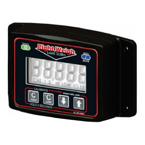
- Page 1 Exterior Digital Load Scale 201-EDG-02(B) Installation and Operation Manual Please read carefully before installation...
-
Page 2: Table Of Contents
Exterior Digital Load Scale 201-EDG-02(B) Table of Contents Specifications & Overview Scale Installation and Electrical Connections Calibration Operating and Weighing Instructions Scale Operating Modes Independent Mode (IdP) Estimated Steer + Average (S-AVG) Estimated Steer + Independent (S-IdP) Multiple Calibration Mode (4CAL) -
Page 3: Specifications & Overview
Specifications & Overview The Right Weigh 201-EDG-02(B) digital load scale has two internal air pressure sensors. This scale will monitor one air suspension axle group with two Height Control Valves (HCVs) or 2 axle groups with one HCV each. An axle group can be either a single, tandem, or triple set of axles on the truck or trailer. - Page 4 Specifications & Overview Drop Axle: This load scale can be used to monitor an axle group with an air ride lift axle if the lift axle air bags are controlled by the same height control valve as the other axles in the group. The scale will need to be setup using multiple calibration mode.
-
Page 5: Scale Installation And Electrical Connections
Scale Installation and Electrical Connections The 201-EDG-02 is designed to be mounted on the outside of a truck or trailer, however the 201-EDG-02 must still be mounted in a protective enclosure. A protective box and mounting bracket are included with the 201- EDG-02B. - Page 6 Appendix A. 4: Install a new 1/4” air line and fitting to be used with the Right Weigh load scale into the street tee. Run the new air line from the street tee fitting to the mounting location of the scale.
-
Page 7: Calibration
1: While the vehicle is empty, obtain a weight from a certified in-ground scale for the specific axle group or groups attached to the Right Weigh load scale. 2: Park on a level surface. Shift the transmission to neutral and set the parking brakes. - Page 8 Loaded Calibration Point 1: While the vehicle is fully loaded, obtain a weight from a certified in-ground scale for the specific axle group or groups attached to the Right Weigh load scale. 2: Park on a level surface. Shift the transmission to neutral and set the parking brakes.
-
Page 9: Operating And Weighing Instructions
HCV to refill the system. (This may take several minutes depending on the type of HCV.) 4: Press the ON/OFF button to turn on the Right Weigh load scale. 5: Adjust the suspension or the load itself until the Right Weigh load scale displays a weight value below your legal limit. -
Page 10: Scale Operating Modes
Scale Operating Modes The next few pages cover the operation modes that are built into the 201-EDG- 02(B). The load scale can only be setup in one operating mode at a time. If the mode is changed, the calibration data will be reset to factory defaults, requiring re-calibration. -
Page 11: Independent Mode (Idp)
Independent Mode (IdP) In Independent mode, a 201-EDG-02(B) can monitor the drive and trailer axle groups of a dedicated tractor-trailer set with single HCV drives and single HCV trailer. In this mode, there is a small number in the lower right of the display, either a 1, 2, or 1 &... - Page 12 Independent Mode (IdP) Empty Calibration Point 1: Obtain separate empty weight values for the drive axle and trailer axle groups from a certified in-ground scale. 2: Press the MENU button until the scale is displays axle group 1. Press and hold C LOW until the “C/L” symbol appears. 3: Adjust the value using the UP and DOWN arrows so that it matches your scale ticket for axle group 1.
- Page 13 Estimated Steer Mode - Average (S-AVG) In Estimated Steer mode, a 201-EDG-02(B) which is installed on a dual leveling valve tractor to monitor the drive axle group, can also estimate the steer axle weight. In this mode, there is a small number in the lower left of the display, either 1, 2, or 1 &...
-
Page 14: Estimated Steer + Average (S-Avg)
Estimated Steer Mode - Average (S-AVG) Empty Calibration Point 1: Obtain separate empty weight values for the steer axle and drive axle group from an in-ground scale. 2: Press the MENU button until the scale displays axle group 1. Press and hold the C LOW button until the “C/L” symbol appears. -
Page 15: Estimated Steer + Independent (S-Idp)
Estimated Steer Mode - Independent (S-IdP) A 201-EDG-02(B) can estimate the steer axle weight when setup to monitor a dedicated tractor-trailer set. In Estimated Steer—Independent mode, sensor A is connected to a single HCV drive axle group, and sensor B is connected to a single HCV trailer axle group. - Page 16 Estimated Steer Mode - Independent (S-IdP) Empty Calibration Point 1: Obtain separate empty weight values for the steer axle, drive axle group, and trailer axle group from a certified in-ground scale. 2: Press the MENU button until the scale displays axle group 1. Press and hold the C LOW button until the “C/L”...
-
Page 17: Multiple Calibration Mode (4Cal)
Multiple Calibration Mode (4CAL) The 201-EDG-02(B) digital load scale can be used in a mode which stores 4 sets of calibration data. This can be useful for an axle group which has an integrated air ride lift axle using the same HCV, or a suspension which has many operating conditions. -
Page 18: Security Pin Code
Security PIN Code A security PIN code can be added to the 201-EDG-02(B) to prevent tampering with the scale. It will need to be entered to change the calibration values, or to change the PIN code. Keep a copy of the PIN code for future use. -
Page 19: Overweight Warning
Overweight Warning As an added visual warning, the display can be set to flash when above a set weight. For example, you may choose to have the display flash any time the weight on the axle group goes above 33,500 pounds. Setting an Overweight Warning 1: With the scale turned on, press and hold the C HIGH and C LOW buttons. -
Page 20: Troubleshooting
(refer to scale operating instructions for proper procedure). Drive the vehicle around the block and return to the same location. Acquire a second reading from the Right Weigh load scale. If the two readings are significantly different, then the HCV might be malfunctioning. - Page 21 Troubleshooting Scale does not power on: Scale is not If there is a bad connection in the circuit which causes voltage to drop below 9 volts, the scale will not power connected to a on. Test the power source with a voltmeter. switched power source of between 9 and 32 volts...
-
Page 22: Appendix A - Additional Parts
The following is a list of additional parts needed for air line installation. This list is just a suggestion and may not be all of the parts needed for your specific vehicle. Check with your Right Weigh dealer for optional installation kits. -
Page 23: Appendix B - Wiring Insulation
Appendix B - Wiring Insulation It is very important that all wiring connections be made watertight. Connections which are not watertight will allow moisture to travel through the individual strands of the wires and make it’s way into the scale, causing permanent damage to the electronics.
Need help?
Do you have a question about the 201-EDG-02 and is the answer not in the manual?
Questions and answers