Right Weigh 201-EBT-01 Installation & Operation Manual
Onboard load scale
Hide thumbs
Also See for 201-EBT-01:
- Installation & operation manual (28 pages) ,
- Installation & operation manual (24 pages) ,
- Installation and operation manual (36 pages)

Related Manuals for Right Weigh 201-EBT-01


Summary of Contents for Right Weigh 201-EBT-01
- Page 1 INSTALLATION & OPERATION MANUAL Scan here to download the Right Weigh App! ONBOARD LOAD SCALE EXTERIOR DIGITAL 201-EBT-01(B)
- Page 2 The installation steps in this manual are for the sole use of trained installers. Right Weigh, Inc. accepts no responsibility or liability for issues involving, but not limited to, incorrect installation that occur from misinterpretation of the steps outlined in this document.
-
Page 3: Table Of Contents
CONTENTS Specifications & Overview Installation Getting Started Operating Modes Truck Trailer / Dolly Gauge Operation Calibration Empty Loaded Security PIN Code (Optional) Operating & Weighing Keypad Function Glossary Diagnostics RS232 Configuration Troubleshooting Appendix A Appendix B Appendix C Warranty Statement, Return Policy, & Repairs... -
Page 4: Specifications & Overview
SPECIFICATIONS & OVERVIEW The Right Weigh 201-EBT-01(B) digital load scale has one internal air pressure sensor. This scale will monitor one air suspension single, tandem, or tridem drive axle group or trailer axle group with one Height Control Valve (HCV). - Page 5 SPECIFICATIONS & OVERVIEW Drop Axle: This load scale can be used to monitor one axle group with an air ride lift axle if the lift axle air bags are controlled by the same height control valve as the other axles in the group. The scale will need to be setup using multiple calibration mode. Refer to the Operating Modes section for more information.
- Page 6 Remote Sensor Feature: The 201-EBT-01(B) scale has the capability of connecting to a Right Weigh Remote Sensor that has been installed on a separate vehicle, most commonly used in drop & hook situations. To use this feature, a separate 403-SK, and RTK-01 or RTK-02 kit must be purchased to connect to a trailer.
- Page 7 SPECIFICATIONS & OVERVIEW Right Weigh Load Scales App: Scan here to download the “Right Scan here for instructions about how to Weigh Load Scales” App directly from connect to your scale(s) and use the app the App store along with a video tutorial Technical Specifications:...
- Page 8 SPECIFICATIONS & OVERVIEW 114 mm 208 mm 7-¼” 87 mm 114 mm 184 mm 406 mm 5” 127 mm MENU/ ENTER POWER ON/OFF 27⁄16” 62 mm UP ARROW CAL HIGH CAL LOW DOWN ARROW...
-
Page 9: Installation
INSTALLATION CHOOSE LOCATION The 201 series scale is designed to be mounted on the outside of a truck or trailer, however it must still be mounted in a protective enclosure. A protective box and mounting bracket are included with the 201 scale. Be sure to choose a location that is easily accessible and safe from potential damage (forklift posts, tire caps, etc.) DO NOT mount the scale directly to the chassis or any other main beam unless it is approved by... - Page 10 INSTALLATION INSTALL NEW STREET TEE FITTING Remove the suspension air line fitting from the top of one of the air bags. Street tee Air Bag Insert a street tee fitting into the top of the air bag that matches the thread size tting of the vehicle suspension.
- Page 11 INSTALLATION If using the Remote Sensor Feature, stop these instructions at this time and follow the instructions on the 403-SK installation manual to finish product installation. INSTALL POWER CABLE Insert the male connector on the harness onto the female connector on the back of the scale. Make sure to orient the connector properly so that the small cutout on both connectors line up.
-
Page 12: Getting Started
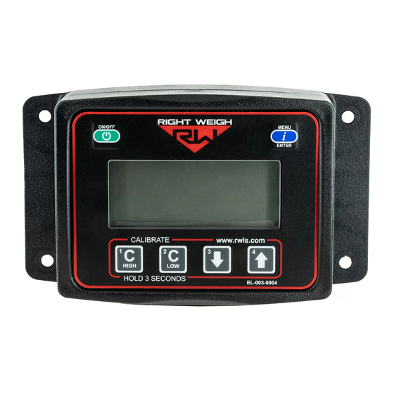
GETTING STARTED ON/OFF MENU POWER MENU / ENTER ENTER WEIGHT AXLE GROUP 2 3 4 C/H C/L KG UNITS INDICATOR www.rwls.com CALIBRATE CALIBRATE ARROWS HIGH HOLD 3 SECONDS EL-003-0004 CALIBRATION INDICATORS... - Page 13 GETTING STARTED POWER Turn the scale on and off to view axle group weights. WEIGHT Weight of the selected axle group. AXLE GROUP INDICATOR Indicates which axle group is being displayed. No indicator mean the gross weight is being displayed and a flashing indicator means the remote sensor weight is being displayed.
-
Page 14: Operating Modes
OPERATING MODES Each vehicle configuration requires a specific operating mode. The modes available on this gauge are: AVG -Tractor or Trailer, One Axle Group S-AVG - Tractor Drive’s and Estimated Steer 4CAL - Trailer, One Axle Group with Multiple Configurations See the tables on the following pages to find your vehicle configuration and set the gauge to the corresponding operating mode. -
Page 15: Truck
OPERATING MODES The numbers on the images indicate the axle groups that will be displayed on the gauge. To cycle through the axle group on the AIR SUSPENSION SPRING SUSPENSION gauge, press the MENU button. TRUCK VEHICLE CONFIGURATION OPERATING MODE Axle Group 1 - Estimated Steer Axle Group 2 - Air Suspension Single, Tandem, or Tri Axle Group (1 HCV) 1 2 3 4... -
Page 16: Trailer / Dolly
OPERATING MODES TRAILER / DOLLY VEHICLE CONFIGURATION OPERATING MODE Axle Group 1 - Air Suspension Single, Tandem, or Tri Axle Group (1 HCV) 1 2 3 4 C/H C/L KG LBS In 4CAL mode, the scale Air Suspension Single, Tandem, or Tri EXAMPLE: can store four sets of Axle Group (1 HCV) with 1 Integrated... - Page 17 OPERATING MODES TRAILER / DOLLY VEHICLE CONFIGURATION OPERATING MODE On some 4-axle EXAMPLE: Air Suspension Single, Tandem, or Tri heavy-haul trailers, Axle Group (1 HCV) with 2 Integrated there are two fixed Air Ride Lift Axles axles, a lift axle, and a flip axle all on the same HCV.
-
Page 18: Gauge Operation
GAUGE OPERATION Press the ON/OFF button to turn on the scale display. PRESS ON/OFF ON/OFF MENU MENU The small numbers at the bottom left of the screen ENTER ENTER indicate which axle group is currently being displayed. 1 2 3 4 C/H C/L KG LBS 2 3 4 C/H C/L KG... -
Page 19: Calibration
CALIBRATION CHANGING UNITS With the gauge on, press and hold the UP ARROW and then press the MENU button. This will toggle the settings between pounds and kilograms. CALIBRATION The 201 series load scale must be calibrated both empty and loaded to work properly. The scale associates the weight you enter with the air pressure values at the time of calibration. -
Page 20: Empty
3: Make sure the Height Control Valve (HCV) has fully inflated the air bags. If needed, briefly dump the air from the suspension and allow the HCV to refill the system. 4: Press the ON/OFF button to turn on the Right Weigh load scale. 5: Press the blue MENU button to select the proper axle group or calibration set. -
Page 21: Loaded
3: Make sure the Height Control Valve (HCV) has fully inflated the air bags. If needed, briefly dump the air from the suspension and allow the HCV to refill the system. 4: Press the ON/OFF button to turn on the Right Weigh load scale. 5: Press the blue MENU button to select the proper axle group or calibration set. -
Page 22: Security Pin Code (Optional)
Once the PIN code feature is enabled, it can be changed but the feature cannot be disabled without resetting the calibration values. If you would like to disable the PIN code feature, please call Right Weigh Technical Support listed on page 2. - Page 23 SECURITY PIN CODE (OPTIONAL) CHANGE PIN CODE PRESS With the gauge off, press and hold both the C LOW and C HIGH buttons, then press the ON/OFF button. Release all three buttons. The gauge will display "CodE". HOLDING PRESS Press the MENU button and “-----” will display on the screen. Enter the previous PIN code.
-
Page 24: Operating & Weighing
4: Press the ON/OFF button to turn on the Right Weigh load scale. 5: Adjust the suspension or the load itself until the Right Weigh load scale displays a weight value below your legal limit. 6: Press the blue MENU button to display other axle groups or calibration sets. -
Page 25: Keypad Function Glossary
KEYPAD FUNCTION GLOSSARY BUTTON SEQUENCE DESCRIPTION FUNCTION HOLD PRESS Power the display on or off . Power On / Off Note: Pressing the ON/OFF button while in a configuration menu saves the selection and powers off the display. Next Axle Group / Cycles to the next axle group or menu screen. - Page 26 KEYPAD FUNCTION GLOSSARY BUTTON SEQUENCE DESCRIPTION FUNCTION HOLD PRESS With the gauge off, use this key sequence to PIN Code create or change an existing PIN code. See Security PIN Code section. HIGH With the display off, use this key sequence to Diagnostics Menu enter the diagnostics menu and view diagnostic data for the gauge.
- Page 27 KEYPAD FUNCTION GLOSSARY BUTTON SEQUENCE DESCRIPTION FUNCTION HOLD PRESS While calibration is enabled, adjust the weight Adjust Weight value using the UP and DOWN arrows Value The UP arrow is used to change selections in Next Selection the menu screens. With the display off, use this sequence to Set Measurement change the measurement mode.
-
Page 28: Diagnostics
DIAGNOSTICS Entering the diagnostics menu can be helpful in performing regular maintenance, diagnosing a problem, and taking a deeper look into the current state of the gauge. The following instructions show how to enter the diagnostic menu and navigate through each of the diagnostics screens. HOLD PRESS ON/OFF... - Page 29 DIAGNOSTICS AIR SENSOR(S) (screen #5) This screen displays the air suspension pressure (in psi) measured by the internal air sensor(s) and should be between 18 and 90 psi with the vehicle’s air bags inflated. If applicable, press the UP arrow to display the pressures for the 1 2 3 4 C/H C/L KG LBS 1 2 3 4...
- Page 30 C/H C/L KG LBS CEntr - connected in between two other Right Weigh gauges End - connected to another Right Weigh gauge, end [back] of the chain Press the MENU button to go back to screen #1 and then press the ON/OFF button...
-
Page 31: Rs232 Configuration
When the display turns on the first screen will contain the messaging protocol setting. Press the UP arrow button to cycle through the available options. 232-1 - default messaging protocol For details on Right Weigh RS232 messaging protocol visit: https:/ /rwls.com/wp-content/uploads/2022/07/rwlsnmeaserialdatainterfacespec-v4.1.pdf 1 2 3 4... -
Page 32: Troubleshooting
(refer to gauge operating instructions for proper procedure). Drive the vehicle around the block and return to the same location. Acquire a second reading from the Right Weigh gauge. If the two readings are significantly different, then the HCV might be malfunctioning. - Page 33 TROUBLESHOOTING PROBLEM SOLUTION CAUSE Gauge reading “noAir” One or more air inputs are not Check that all air inputs are receiving air. Pull airline out of air fitting(s) on receiving air (If 2 air sensors the back of the gauge. Follow the airline along the vehicle to the airbags to are set to Average mode and check that it hasn’t been pinched or damaged.
- Page 34 TROUBLESHOOTING PROBLEM SOLUTION CAUSE Scale Does Not Power Connect the scale to a switched power source between 9 and 32 VDC Scale is not connected to a switched power source of (typically either the vehicle marker lights or the AUX/ABS wire). If there is between 9 and 32 VDC a bad connection in the circuit which causes voltage to drop below 9 volts, the scale will not power on.
- Page 35 The following is a list of additional parts needed for air line installation. This list is just a suggestion and may not be all of the parts needed for your specific vehicle. Check with your Right Weigh dealer for optional installation kits.
- Page 36 APPENDIX B It is very important that all wiring connections be made watertight. Connections which are not watertight can allow moisture to travel through the individual strands of the wires and make it’s way into the scale, causing permanent damage to the electronics. Crimp each end of the wire into the connector with a wire crimp tool (tool not provided).
- Page 37 The steer axle weight can be estimated because the weight placed on a fixed position 5th wheel is in a consistent, predictable location on the frame. After calibration, the Right Weigh gauge calculates how many pounds of weight are typically placed on the steer axle, for every pound placed on the drive axle group.
- Page 38 5. Natural disasters, including but not limited to lightning strikes, floods, fires, earthquakes, etc. Under this warranty, Right Weigh, Inc.'s liability is limited to the original cost of the product in question and does not extend to labor costs or other expenses related to installation, removal, or replacement of a Right Weigh, Inc.
- Page 39 Right Weigh, Inc. will evaluate the returned product(s) at no charge. If the product is determined to be under warranty, it will be repaired or replaced with equivalent product(s). Right Weigh, Inc. will cover the cost of shipping the warrantied product back to the customer using a shipping method of our choosing, equal to or faster than the method used by the customer.
- Page 40 THANK YOU FOR YOUR BUSINESS SCAN HERE FOR ADDITIONAL RESOURCES AND VIDEOS www.rwls.com/manuals-resources/ RightWeighInc rightweigh_inc rwlsinc right-weigh-inc- Right Weigh, Inc. PP-003-0010 Revision V ©2015-2024 Right Weigh, Inc. All rights reserved. Hillsboro, Oregon USA March 2024...
Need help?
Do you have a question about the 201-EBT-01 and is the answer not in the manual?
Questions and answers