Right Weigh 201-EBT-04B Installation & Operation Manual
Onboard load scale exterior digital
Hide thumbs
Also See for 201-EBT-04B:
- Installation & operation manual (40 pages) ,
- Installation, calibration, and maintenance log (4 pages) ,
- Installation and maintenance (4 pages)

Related Manuals for Right Weigh 201-EBT-04B


Summary of Contents for Right Weigh 201-EBT-04B
- Page 1 ONBOARD LOAD SCALE EXTERIOR DIGITAL 201-EBT-04(B) Scan here to download the Right Weigh App!
- Page 2 The installation steps in this manual are for the sole use of trained installers. Right Weigh, Inc. accepts no responsibility or liability for issues involving, but not limited to, incorrect installation that occur from misinterpretation of the steps outlined in this document.
-
Page 3: Table Of Contents
EXTERIOR DIGITAL 201-EBT-04(B) The Bluetooth® word mark and logos are registered trademarks owned by Bluetooth SIG, Inc. and any use of such marks by Right Weigh, Inc. is under license. Other trademarks and trade names are those of their respective owners. -
Page 4: Specifications & Overview
SPECIFICATIONS & OVERVIEW The Right Weigh 201-EBT-04(B) digital load scale has four internal air pressure sensors. This scale will monitor one air suspension axle group with four Height Control Valves (HCVs) or four axle groups with one HCV each. An axle group can be either a single, tandem, or triple set of axles on the truck or trailer. - Page 5 fifth wheel. Remote Sensor Feature: The 201-EBT-04(B) scale has the capability of connecting to a Right Weigh Remote Sensor that has been installed on a separate vehicle, most commonly used in drop & hook situations. To use this feature, a separate 403-SK, and RTK-01 or RTK-02 kit must be purchased to connect to a trailer.
- Page 6 SPECIFICATIONS & OVERVIEW Right Weigh Load Scales App: Scan here to download Scan here for instructions “Right Weigh Load Scales” about how to connect to App directly from the App your scale(s) and use the app store along with a video tutorial Technical Specifications:...
-
Page 7: Scale Installation And Electrical Connections
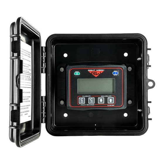
The 201-EBT-04 scale is designed to be mounted on the outside of a truck or trailer, however it must still be mounted in a protective enclosure. A protective box and mounting bracket are included with the 201-EBT-04B. Be sure to choose a location that is easily accessible and safe from potential damage (forklift posts, tire caps, etc.) - Page 8 SCALE INSTALLATION & ELECTRICAL CONNECTIONS INSTALL NEW STREET TEE FITTING Remove the suspension air line fitting from the top of one of the air bags. Air Bag Insert a street tee fitting into the top of the air bag that matches the thread size of the Street tee vehicle suspension.
- Page 9 SCALE INSTALLATION & ELECTRICAL CONNECTIONS If using the Remote Sensor Feature, stop these instructions at this time and follow the instructions on the 403-SK installation manual to finish product installation. INSTALL POWER CABLE CONNECTION HARNESS BLACK = GROUND RED = POWER Insert the male connector on the harness onto the female connector on the back of the scale.
-
Page 10: Operating Modes
OPERATING MODES Each vehicle configuration requires a specific operating mode. The modes available on this gauge are: AVG -Tractor or Trailer, One Axle Group (4 HCV) S-AVG - Tractor Drive’s (4 HCV) and Estimated Steer F2b2 - Tractor, Straight Truck, Bus, or Fertilizer Spreader Steer (2 HCV) and Drive (2 HCV) Axle Groups See the tables on the following pages to find your vehicle configuration and set the gauge to the corresponding operating mode. -
Page 11: Tractor
OPERATING MODES The numbers on the images indicate the axle groups that will be displayed on the gauge. To cycle through the axle group on AIR SUSPENSION SPRING SUSPENSION the gauge, press the MENU button. TRACTOR VEHICLE CONFIGURATION OPERATING MODE Axle Group 1 - Estimated Steer Axle Group 2 - Air Suspension ON/OFF... -
Page 12: Calibration & Unit Of Measure
HCV to refill the system. 4: Press the ON/OFF button to turn on the Right Weigh load scale. 5: Press the blue MENU button to select the proper axle group or calibration set. - Page 13 CALIBRATION & UNIT OF MEASURE 4: Press the ON/OFF button to turn on the Right Weigh load scale. 5: Press the blue MENU button to select the proper axle group or calibration set. 6: Press and hold the C HIGH button until the “C/H” symbol appears.
-
Page 14: Security Pin Code
5 digit number will be required for calibration at any time. Once the PIN code is set, it cannot be removed. If you set the PIN code and would like it removed, please call Right Weigh Technical Support listed on page 2. SET PIN CODE With the gauge off, press and hold both the C... -
Page 15: Operate & Weigh
4: Press the ON/OFF button to turn on the Right Weigh load scale. 5: Adjust the suspension or the load itself until the Right Weigh load scale displays a weight value below your legal limit. 6: Press the blue MENU button to display other axle groups or calibration sets. -
Page 16: Troubleshooting
Drive the vehicle around the block and return to the same location. Acquire a second reading from the Right Weigh gauge. If the two readings are significantly different, then the HCV might be malfunctioning. Check that all air inputs are receiving air. Pull airline out of air Gauge reading “noAir”... - Page 17 PIN before calibration data can be changed. To understand how to code reset the PIN code, see page 16. If the PIN code has been forgotten, please call Right Weigh technical support listed on page 2 for further assistance.
-
Page 18: Appendix A - Additional Parts
APPENDIX A The following is a list of additional parts needed for air line installation. This list is just a suggestion and may not be all of the parts needed for your specific vehicle. These parts are sold separately in the 103-SK kit: 1/4 Inch Air Line Approximately 6 to 9 meters... -
Page 19: Appendix B - Wiring Insulation
APPENDIX B It is important that all wiring connections be made watertight. Connections which are not watertight can develop corrosion and result in loss of contact over time. Heat shrink type butt connectors are recommended. Crimp each end of the wire into the connector with a wire crimp tool (tool not provided). -
Page 20: Appendix C - Estimated Steer
fixed position 5th wheel is in a consistent, predictable location on the frame. After calibration, the Right Weigh gauge calculates how many pounds of weight are typically placed on the steer axle, for every pound placed on the drive axle group. -
Page 21: Notes
NOTES... -
Page 22: Warranty Statement
NOTES... -
Page 23: Return Policy & Repairs
In no event shall Right Weigh, Inc. be liable for direct, indirect, special, incidental or consequential damages (including loss of profits or loss of time) resulting from the performance of a Right Weigh, Inc. product. In all cases, Right Weigh, Inc. liability will be limited to the original cost of the product in question. Right Weigh, Inc. reserves the right to make improvements in design, construction, and appearance of products without notice. - Page 24 SCAN FOR ADDITIONAL RESOURCES www.rwls.com/manuals-resources/ CONTACT US FOR FOLLOW US! ADDITIONAL SUPPORT RightWeighInc (503) 628-0838 rightweigh_inc support@rwls.com rwlsinc right-weigh-inc- www.rwls.com PP-003-0034 Revision G Right Weigh, Inc. February 2022 Hillsboro, Oregon USA ©2015-2022 Right Weigh, Inc. All rights reserved.
Need help?
Do you have a question about the 201-EBT-04B and is the answer not in the manual?
Questions and answers