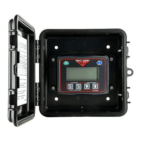
Right Weigh 201-EBT-02 Installation & Operation Manual
Onboard load scale exterior digita
Hide thumbs
Also See for 201-EBT-02:
- Installation & operation manual (28 pages) ,
- Installation & operation manual (44 pages)
Table of Contents
Advertisement
Quick Links
Advertisement
Table of Contents

Related Manuals for Right Weigh 201-EBT-02


Summary of Contents for Right Weigh 201-EBT-02
- Page 1 ONBOARD LOAD SCALE 201-EBT-02(B) EXTERIOR DIGITAL...
- Page 2 The installation steps in this manual are for the sole use of trained installers. Right Weigh, Inc. accepts no responsibility or liability for issues involving, but not limited to, incorrect installation that occur from misinterpretation of the steps outlined in this document.
-
Page 3: Table Of Contents
EXTERIOR DIGITAL The Bluetooth® word mark and logos are registered trademarks owned by Bluetooth SIG, Inc. and any use of such marks by Right Weigh, Inc. is under license. Other trademarks and trade names are those of their respective owners. -
Page 4: Specifications & Overview
SPECIFICATIONS & OVERVIEW The Right Weigh 201-EBT-02(B) digital load scale has two internal air pressure sensors. This scale will monitor one air suspension axle group with two Height Control Valves (HCV) or two axle groups with one HCV each. An axle group can be either a single, tandem, or triple set of axles on the truck or trailer. - Page 5 201-EBT-12B. Remote Sensor Feature: The 201-EBT-02(B) scale has the capability of connecting to a remote sensor that has been installed on a separate vehicle, most commonly used in drop & hook situations. For more information about this feature, please refer to the separate 403-SK Installation Instruction Manual (PP-003-0084).
- Page 6 SPECIFICATIONS & OVERVIEW Technical Specifications: Operating Temperature: -22° F to +185° F (-30° C to +85° C) Storage Temperature: -40° F to +185° F (-40° C to +85° C) Power Requirement: 9 VDC to 32 VDC (Switched) Units: Pounds (LBS) or Kilograms (KG) Housing: High impact polycarbonate blend Display: 0.8”...
-
Page 7: Tca Compliance Information
TCA COMPLIANCE INFORMATION The 201-EBT-02B is a Transport Certification Australia (TCA) Type-Approved Mass Sensor Unit (MSU) part of a Type-Approved On-Board Mass (OBM) system. This organization approves automotive technology that follows a set of guidelines to ensure consumer safety and device reliability. For more information visit their website at: https:/ /tca.gov.au/publication/obm-system-specification/ The 201-EBT-02B is approved for use in both Category A and Category B... - Page 8 TELEMATICS DEVICE The prime mover must have an approved telematics device installed and the device must be connected to the Right Weigh system. SECURITY SEALS Security seal kit p/n 909-SSK must be used to secure the MSU to the vehicle at the time of installation.
-
Page 9: Scale Installation And Electrical Connections
& ELECTRICAL CONNECTIONS CHOOSE LOCATION The 201-EBT-02 scale is designed to be mounted on the outside of a truck or trailer, however it must still be mounted in a protective enclosure. A protective box and mounting bracket are included with the 201-EBT-02B. - Page 10 SCALE INSTALLATION & ELECTRICAL CONNECTIONS CUT EXISTING AIR LINE Cut the air line going to one of the air bags in the suspension group to be monitored. ASSEMBLE TEE FITTING Choose a tee fitting that matches the size of the existing air line, then install a female NPT tube fitting onto the tee as shown.
- Page 11 SCALE INSTALLATION & ELECTRICAL CONNECTIONS If using the Remote Sensor Feature, stop these instructions at this time and follow the instructions on the 403-SK installation manual to finish product installation. INSTALL POWER CABLE CONNECTION HARNESS BLACK = GROUND RED = POWER Insert the male connector on the harness onto the female connector on the back of the scale.
- Page 12 SCALE INSTALLATION & ELECTRICAL CONNECTIONS LOG INSTALLATION EVENT TCA OBM Requirement: Installation Log (PP-003-0065 page 1) must be completed at the time of installation. For more information on TCA requirements, refer to pages 7-8.
-
Page 13: Operating Modes
OPERATING MODES Each vehicle configuration requires a specific operating mode. The modes available on this gauge are: AVG -Tractor or Trailer, One Axle Group S-AVG - Tractor Drive’s and Estimated Steer 4CAL - Trailer, One Axle Group with Multiple Configurations IDP - Two Axle Groups S-IDP - Tractor Drive and Trailer Axle Groups and Estimated Steer See the tables on the following pages to find your vehicle configuration and set the... -
Page 14: Tractor
OPERATING MODES The numbers on the images indicate the axle groups that will be displayed on the gauge. To cycle through the axle group on AIR SUSPENSION SPRING SUSPENSION the gauge, press the MENU button. TRACTOR VEHICLE CONFIGURATION OPERATING MODE Axle Group 1 - Estimated Steer Axle Group 2 - Air Suspension ON/OFF... -
Page 15: Dedicated Tractor-Trailer Set
OPERATING MODES DEDICATED TRACTOR-TRAILER SET VEHICLE CONFIGURATION OPERATING MODE ON/OFF MENU ENTER (ESTIMATED) 1 2 3 4 C/H C/L KG LBS Axle Group 1 - Estimated Steer CALIBRATE www.rwls.com HIGH HOLD 3 SECONDS EL-003-0004 Axle Group 2 - Drive Axle Group Air Suspension Single, Tandem, or Tri Axle Group (1 HCV) Axle Group 3 - Trailer Axle Group Air Suspension Single, Tandem, or Tri Axle Group (1 HCV) -
Page 16: Trailer / Dolly
OPERATING MODES TRAILER / DOLLY VEHICLE CONFIGURATION OPERATING MODE EXAMPLE: Air Suspension Single, Tandem, or Tri Axle Group (2 HCV) with 1 Integrated Air Ride Lift Axle This trailer axle group has 1 integrated lift axle. Calibration set “1” is when the lift axle is up and set “2”... -
Page 17: Calibration & Unit Of Measure
CALIBRATION The 201-EBT-02(B) load scale must be calibrated both empty and loaded to work properly. The scale associates the weight you enter with the air pressure in the suspension system at the time of calibration. You will need to calibrate once while the vehicle is empty, and again while the vehicle is loaded for each axle group being monitored. - Page 18 CALIBRATION & UNIT OF MEASURE 4: Press the ON/OFF button to turn on the Right Weigh load scale. 5: Press the blue MENU button to select the proper axle group or calibration set. 6: Press and hold the C HIGH button until the “C/H” symbol appears.
-
Page 19: Security Pin Code
SET SECURITY PIN CODE PRESS With the gauge off, press and hold both the C LOW and C HIGH buttons, then press the ON/OFF button. Release all three buttons. The gauge will display "CodE". HOLDING Press the MENU button and PRESS “00000”... -
Page 20: Change
CHANGE SECURITY PIN CODE PRESS With the gauge off, press and hold both the C LOW and C HIGH buttons, then press the ON/OFF button. Release all three buttons. The gauge will display "CodE". HOLDING Press the MENU button and PRESS “-----”... -
Page 21: Operate & Weigh
4: Press the ON/OFF button to turn on the Right Weigh load scale. 5: Adjust the suspension or the load itself until the Right Weigh load scale displays a weight value below your legal limit. 6: Press the blue MENU button to display other axle groups or calibration sets. -
Page 22: Mobile Device Connection
MOBILE DEVICE CONNECTION RIGHT WEIGH LOAD SCALES APP download Scan here to the “Right Weigh Load Scales” App directly from the App store TCA OBM Requirement: To comply with TCA requirements, a special app MUST always be used and setup properly to view vehicle weight. For Category B applications, this app must also be connected to a TCA approved telematics partner on the smart device anytime the vehicle is in use. -
Page 23: Maintenance
MAINTENANCE To be sure the gauge remains accurate, proper maintenance and re-calibration is required every 6 months or when changes/repairs to the suspension have taken place. Follow the steps on the Maintenance Log (PP-003-0065 page 4) and check the corresponding box after each test is performed with a passing result. Once all tests are passed, re-calibrate the gauge;... -
Page 24: Troubleshooting
Drive the vehicle around the block and return to the same location. Acquire a second reading from the Right Weigh gauge. If the two readings are significantly different, then the HCV might be malfunctioning. Check that all air inputs are receiving air. Pull airline out of air One or more air inputs are Gauge reading “noAir”... - Page 25 PIN before calibration data can be changed. To understand how to code reset the PIN code, see page 16. If the PIN code has been forgotten, please call Right Weigh technical support listed on page 2 for further assistance.
-
Page 26: Appendix A - Additional Parts
APPENDIX A The following is a list of additional parts needed for air line installation. This list is just a suggestion and may not be all of the parts needed for your specific vehicle. These parts are sold separately in the 103-SK kit: 1/4 Inch Air Line Approximately 6 to 9 meters... -
Page 27: Appendix B - Wiring Insulation
APPENDIX B It is important that all wiring connections be made watertight. Connections which are not watertight can develop corrosion and result in loss of contact over time. Heat shrink type butt connectors are recommended. Crimp each end of the wire into the connector with a wire crimp tool (tool not provided). -
Page 28: Appendix C - Estimated Steer
APPENDIX C ESTIMATED STEER Estimated Steer is an estimated readout of the steer axle weight without using a sensor on the steer axle. The way this works is the user inputs calibration data for the steer axle both empty and loaded. The scale associates the entered weights to the pressure measured from the drive axle air suspension at the time of calibration. -
Page 29: Revision Log
REVISION LOG SUMMARY AUTHORIZED BY REVISION DATE Preliminary Release H. Gooding 10/15/20 Added 12 pin connector and Drop & Hook Trailer connection 1/4/21 H. Gooding instructions Removed overweight warning 4/7/21 H. Gooding Moved remote sensor feature to separate manual 8/5/21 H. -
Page 30: Warranty Statement
(including loss of profits or loss of time) resulting from the performance of a Right Weigh, Inc. product. In all cases, Right Weigh, Inc. liability will be limited to the original cost of the product in question. Right Weigh, Inc. reserves the right to make improvements in design, construction, and... -
Page 31: Return Policy & Repairs
Right Weigh, Inc. will return the product at its expense via a shipping method (carrier to be at sole discretion of Right Weigh, Inc.) equal to or faster than the method used by the customer. Products or parts thereof not covered by warranty will be repaired or replaced at customer expense upon authorization by the customer. - Page 32 SCAN FOR ADDITIONAL RESOURCES rightweigh.com.au/manuals-resources/ CONTACT US FOR FOLLOW US! ADDITIONAL SUPPORT RightWeighInc +61 418 622840 rightweigh_inc leigh@rwls.com.au rwlsinc right-weigh-inc- rightweigh.com.au PP-003-0073 Revision E Right Weigh, Inc. October 2021 Hillsboro, Oregon USA ©2015-2021 Right Weigh, Inc. All rights reserved.
Need help?
Do you have a question about the 201-EBT-02 and is the answer not in the manual?
Questions and answers