
Subscribe to Our Youtube Channel
Related Manuals for CyberData 10807


Summary of Contents for CyberData 10807
- Page 1 4-Port PoweredUSB 2.0 Hub Operations Guide with External Power Supply Part #010807 CyberData Corporation 2555 Garden Road Monterey, CA 93940 (831) 373-2601 930103E...
- Page 2 CyberData Corporation. This manual, and the products, software, firmware, and/or hardware described in this manual are the property of CyberData Corporation, provided under the terms of an agreement between CyberData Corporation and recipient of this manual, and their use is subject to that agreement and its terms.
-
Page 3: Table Of Contents
Appendix A Regulatory and Safety Information Appendix B Setting up the Hub on Windows XP Appendix C Troubleshooting/Technical Support C.1 Frequently Asked Questions (FAQ) ...18 C.2 Documentation ...18 C.3 Contact Information ...18 C.4 Warranty ...19 Index Operations Guide 930103E CyberData Corporation... -
Page 4: Chapter 1 Product Overview
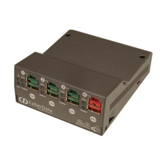
This add-on Hub makes it easy to connect the PC to devices that require more than the 500mA of +5 volts supplied with the standard USB interface. Figure 1-1. CyberData 4-Port PoweredUSB 2.0 Hub 1.1 Product features 4 PoweredUSB ports ●... -
Page 5: License Note
The PoweredUSB controller board contains certain technology that is covered by an IBM CyberData Corporation is licensed with IBM to manufacture, and to sell or lease products that incorporate this technology. This license also permits other entities to resell or release these Cyberdata products after they have been purchased from CyberData. -
Page 6: Dimensions
1.4 Dimensions Operations Guide Figure 1-2. Dimensions 1.78 [45.3] 3.71 [94.3] 4.34 [110.3] Dimensions are in Inches [Millimeter] 930103E Product Overview Dimensions Perspective View View A-A Rear View CyberData Corporation... -
Page 7: Chapter 2 Installing And Using The 4-Port Poweredusb Hub
Section 2.1, "Product Components List" ● Section 2.2, "Product Compatibility" ● Section 2.3, "Installation" ● Section 2.4, "Connections" ● Section 2.5, "Operation" ● Section 2.6, "Port Electrical Specifications" ● Figure 2-3. CyberData 4-Port PoweredUSB 2.0 Hub Operations Guide 930103E CyberData Corporation... -
Page 8: Product Components List
(1) Short USB 2.0 Hi-Speed host cable • (1) Host USB cable strain relief clamp • (1) 4-Port PoweredUSB 2.0 Hub Operations Guide Figure 2-4. CyberData 4-Port PoweredUSB 2.0 Hub—Front View Port Power LED Hub Power LED Link LED Port 1 Status LED Figure 2-5. -
Page 9: Product Compatibility
The SiP VoIP and PoE Speaker is a tabletop unit with mounting feet that sit on a flat surface. Operations Guide Table 2-1. Operating Systems 2.0 Standard PoweredUSB 0.8g 930103E Installing and Using the 4-Port PoweredUSB Hub Product Compatibility CyberData Corporation... -
Page 10: Connections
+24V for +24V for USB Host up to 2.5 up to 6.5 Connector Amp load Amp load (Type B) 930103E Installing and Using the 4-Port PoweredUSB Hub Connections for an illustration of cable routing from the Strain Relief CyberData Corporation... -
Page 11: Host Connector
Section 2.1, "Product Components List" Figure 2-7. Host connector with strain relief Figure 2-9 for an illustration. The lower portion of the “A” connector side on 930103E Installing and Using the 4-Port PoweredUSB Hub Connections for information about the Accessory Kit. CyberData Corporation... -
Page 12: Connector Color Keys
Installing and Using the 4-Port PoweredUSB Hub Connections 24 Volt Keyed 2.3A Ports 4 Signal Description Vbus USB standard “A” USB standard “A” USB standard “A” Ground USB standard “A” Ground USB PlusPower Vplus USB PlusPower Vplus USB PlusPower Ground USB PlusPower Shield CyberData Corporation... -
Page 13: Peripherals Connections To The Sip Voip And Poe Speaker
This figure illustrates the cable routing from the SiP VoIP and PoE Speaker to the Dell Retail Integrator. Figure 2-10. Top view of Hub PoweredUSB cable routing CyberData 4-Port PoweredUSB Hub Operations Guide Installing and Using the 4-Port PoweredUSB Hub... -
Page 14: Peripheral Cable Connection Options
2.4.6 Peripheral Cable Connection Options Figures 10 through 16 provide examples of peripheral cable combinations and connection options for the SiP VoIP and PoE Speaker. The following table provides details about the CyberData PoweredUSB Cables displayed in these figures. PoweredUSB cable... - Page 15 Installing and Using the 4-Port PoweredUSB Hub Connections Figure 2-12. Cables; +12V PoweredUSB to +12V Power Jack and RS-232 to RS-232 Figure 2-13. Cables; +24V PoweredUSB to 3-Pin Mini-DIN and RS-232 to RS-232 or Parallel to Parallel Operations Guide 930103E CyberData Corporation...
- Page 16 Figure 2-14. “Y” Cable, +24V PoweredUSB to 3-Pin Power Mini-DIN and USB “B” Connectors Figure 2-15. RS232 to USB Converter “Y” Cable +12V (PC Enumerates this device as an RS-232 COM port) Figure 2-16. Cable, +24V PoweredUSB to 1x8 PoweredUSB Operations Guide 930103E CyberData Corporation...
-
Page 17: Operation
4. Disable the low-power, standby operation. With this configuration, power is always supplied to the PoweredUSB ports regardless of the PC’s operational state. For more information, contact CyberData as instructed in Operations Guide Installing and Using the 4-Port PoweredUSB Hub Appendix C, "Troubleshooting/Technical... -
Page 18: Port Electrical Specifications
Hub by unplugging it, and then plugging it in again. +12V Ports (3) – 1.5A each ● +24V Port (1) – 2.3A ● Operations Guide Installing and Using the 4-Port PoweredUSB Hub 930103E Port Electrical Specifications CyberData Corporation... -
Page 19: Appendix A Regulatory And Safety Information
• EN61000-3-2: 2000 • EN61000-3-3: 1995 EN55024: 1998 ● • EN61000-4-2: 1995 • EN 61000-4-3:1996 • EN 61000-4-4: 1995 • EN 61000-4-5: 1995 • EN 61000-4-6: 1996 • EN 61000-4-8: 1993 • EN 61000-4-11: 1995 Operations Guide 930103E CyberData Corporation... -
Page 20: Appendix B Setting Up The Hub On Windows Xp
At this point, you should be able to plug in and install a USB device provided you have also installed its drivers, or have them available for installation. Operations Guide 930103E CyberData Corporation... -
Page 21: Appendix C: Troubleshooting/Technical
Phone: 831-373-2601, Extension 136 Email: RMA@CyberData.net When returning a product to CyberData, an approved CyberData RMA number must be printed on the outside of the original shipping package. No product will be accepted for return without an approved RMA number. Send the product, in its original package, to the following address:... -
Page 22: Warranty
CyberData warrants its product against defects in material or workmanship for a period of two years from the date of purchase. Should the product fail within the warranty period, CyberData will repair or replace the product free of charge. This warranty includes all parts and labor. -
Page 23: Index
9 compatibility matrix 6 components list 5 connector color keys 9 CyberData license with IBM 2 CyberData contact information, corporate, sales, tech support, service 18 DC input jacks 7 Dell printer power supply 7 EMC 16 enumeration 14, 17... - Page 24 IP address to the default 18 RMA returned materials authorization 18 short circuit protection 1 technical support, contact information 18 2.0 specification 14 over current 15 warranty 1, 19 Windows XP 14, 17 Operations Guide 930103E CyberData Corporation...
Need help?
Do you have a question about the 10807 and is the answer not in the manual?
Questions and answers