Table of Contents
Advertisement
Quick Links
Advertisement
Table of Contents

Subscribe to Our Youtube Channel
Related Manuals for Snap-On VERSATORQ 2 SYSTEM


Summary of Contents for Snap-On VERSATORQ 2 SYSTEM
- Page 1 ® VERSATORQ®2 SYSTEM...
-
Page 2: Table Of Contents
EC Declaration of Conformity ......17 Maintenance / Calibration Services / . 18 ATEX/UL CERTIFICATONS. Authorized Snap-on Repair Centers ..... . 19... -
Page 3: Safety Warnings And Cautions
VERSATORQ®2 SYSTEM IMPORTANT SAFETY INSTRUCTIONS ® 1. Read this manual completely before using the VERSATORQ2 system. 2. Always wear safety goggles when applying torque to fasteners. 3. To ensure personal safety and prevent equipment damage, make sure that all components, including all sensors, WARNING adaptors, extensions, drivers and sockets are rated to match or exceed the torque being applied. -
Page 4: Introduction
A belt clip on the back of the meter leaves both hands free when working portable. The torque analyzer and the optional sensors can be calibrated by the user with a known torque input. A special memory chip, built into the sensor, identifies the sensor’s range and calibration parameters to any Snap-on VERSATORQ®2 torque analyzer. -
Page 5: Battery Installation / Belt Clip
Battery Installation / Belt Clip The VERSATORQ®2 meter is shipped with three AA batteries installed. Figure 1 Figure 2 Positive Battery Orientation Four 5/64” Hex Screws (6-32 x ½ long) Battery Strap Retaining Clip Two threaded holes for Belt Negative Battery Orientation Clip 1/16”... -
Page 6: Specifications, Meter And Sensors
Specifications Torque Analyzer Sensors Display ..4 Digit w/Alpha & Numerical Function Flags VERSATORQ®2 Sensors provide industry standard square drives. Display Capacity* ....4 Digits They feature a full bridge strain-gage @ 350 Ohms nominal. -
Page 7: Functional Description, Display / Keypad Functions
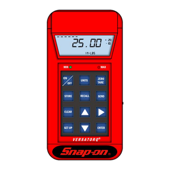
Functional Description – DISPLAY Shows the total number of readings stored in memory. In the The 4 digit, .5 inch, wide angle LCD display shows applied SET-UP mode, these displays indicate the UPPER (+) and torque in TRACK mode or the highest torque value captured in LOWER (-) percentage values for ALARM preset, respectively. -
Page 8: Functional Description, Input/Output
Functional Description – Input/Output SEND END VIEW RIGHT SIDE VIEW DISPLAY BATTERY SAVER EARPHONE JACK POWER SWITCH *MINI-USB PORT SENSOR CONNECTION ALARM SOUNDER MINI USB PORT POWER SWITCH — Disconnects the AA battery source from the VERSATORQ2 circuit. At power-on, unit comes to life, self-checks *WARNING: ONLY USE THE MINI USB PORT IN AREAS KNOWN TO and returns to last SET-UP parameters unless sensor has been BE NON-HAZARDOUS! -
Page 9: Setup, Measurement Modes
SET-UP Measurement Modes At power ON, the torque analyzer does a display check and self-test. It automatically identifies the installed sensor and sets rated UNITS for display. The sensor full scale range is displayed for 2 seconds, then preset torque, upper limit percent and lower limit percent are displayed for 2 seconds. -
Page 10: Measuring Torque / Sleep Mode
How to Measure Torque / Sleep Mode PEAK-HOLD Mode 1. Select the desired torque sensor and connect it to the Caution: If the display ever indicates OVER, discontinue VERSATORQ®2 torque analyzer. torquing and verify the calibration of the sensor. 2. Power ON the torque analyzer using the power switch (See Page 12 and 13) located on the right side. -
Page 11: Store, Off-Load And Clear Memory / Off-Loading To Pc
STORE, RECALL and CLEAR Readings in Memory 4. The file will open excel Tester Serial Number To store a reading in TRACK mode, push the STORE key while Number of values saved torque is being applied. The number of each stored reading is displayed in the small upper numeric display. -
Page 12: Transducer Quick Check / Transducer Calibration Clockwise
Transducer Calibration CW STEP 4 Equipment Required: Precision calibrated test bar and certified calibration weights. • QUICK CHECK With the VERSATORQ®2 torque analyzer in the TRACK mode, (refer to page 9). Apply full load to 100% of sensor rated capacity in the CW (CLOCKWISE) direction 3x. -
Page 13: Transducer Calibration Counter Clockwise
Transducer Calibration CCW STEP 4 Equipment Required: Precision calibrated test bar and certified calibration weights. • Install New Batteries. Use only the batteries listed on page 5 Sensor Calibration CCW (Counterclockwise Direction) 1. Attach a sensor to the VERSATORQ2® meter and power on the unit. Confirm the meter is in the TRACK mode. -
Page 14: Accessories
Accessories VERSATORQ®2 TORQUE AND DATA ANALYZER NOTE: VERSATORQ®2 INCLUDES: VERSATORQ®2 meter MINI-USB CABLE (USBATOMINIB) CARRYING CASE (PB57A) THREE AA BATTERIES (INSTALLED) Belt Clip (276-61) 5/64” HEX KEY (BATTERY INSTALLATION) Optional Sensors Range Part No. Drive Diam. -
Page 15: Notes / Blank
VERSATORQ®2 SYSTEM Notes... - Page 16 VERSATORQ®2 SYSTEM Notes...
-
Page 19: Atex/Ul Certificatons
Clean Meter by wiping with a cloth. DO NOT use solvents, thinners or carburetor cleaners. DO NOT immerse in anything. Service, repair and calibration are to be done by Snap-on Service Centers only. Contact your Snap-on Tools representative. CALIBRATION Contact your Snap-on sales representative for calibration services. - Page 20 Fax: 52-55-53903259 Crystal Lake, Il 60014 Australia Repair Centre China Repair Center: Phone: 815-479-6850 Snap-on Tools Australia PTY.LTD Snap-on Asia Manufacturing (Kunshan) Co. Fax: 815-479-6857 80 Holbeche Road Ltd. Arndell Park NSW 2148 500 Tong Feng Road East Western Repair Center Australia Kunshan, Jiangsu 215300, China.
Need help?
Do you have a question about the VERSATORQ 2 SYSTEM and is the answer not in the manual?
Questions and answers