Table of Contents
Advertisement
Advertisement
Chapters
Table of Contents
Troubleshooting

Related Manuals for Snap-On MT-2500


Summary of Contents for Snap-On MT-2500
- Page 1 OPERATOR’S MANUAL Scanner P/N: 0692E9315-76, Rev:C, PCN:02E0093...
- Page 2 Before installing, maintaining or operating this unit, please read this manual carefully, paying extra attention to the safety warnings and precautions. Copyright 2002 Snap-on UK Holdings Ltd. All rights reserved Snap-on Europe Holding B.V. Spaklerweg 69...
-
Page 3: Table Of Contents
OPERATOR'S MANUAL TABLE OF CONTENTS SAFETY PRECAUTIONS ................... 1 WARNINGS ..................... 1 CAUTIONS ....................3 INTRODUCTION ....................4 OPERATION OVERVIEW ............... 6 OPERATION ....................... 7 1: SCANNER START-UP ................. 7 2: CARTRIDGE SELECTION ..............7 3: IDENTIFICATION ................7 VEHICLE SELECTION ..............8 ABBREVIATIONS ................. - Page 4 OPERATOR'S MANUAL TABLE OF CONTENTS, (CONT’D) 11: CUSTOM SETUP ................29 COMMUNICATION SETUP ............29 ENGLISH / METRIC ..............29 RIGHT / LEFT HAND DRIVE SETUP ........29 LED MENU ................. 30 CONTRAST (BACKLIGHT) ADJUST ......... 30 REMOTE TERMINAL COMMUNICATION ............31 TROUBLESHOOTER ..................
-
Page 5: Safety Precautions
INTRODUCTION SAFETY PRECAUTIONS GENERAL The Scanner and Cartridges have been supplied in a safe condition. In order to keep them in a safe condition and to ensure safe operation of the tester, the operating instructions must be followed and the warnings & cautions must be observed. - Page 6 INTRODUCTION 10: KEEP HANDS AND OTHER OBJECTS AWAY FROM THE ELECTRIC COOLING FAN. THE FAN CAN START UP ANYTIME. 11: BATTERY ACID CAN DAMAGE CLOTHING AND BURN SKIN OR EYES. IF CONTACT IS MADE WITH BATTERY ACID, WASH THE AFFECTED AREA WITH AS MUCH WATER AS POSSIBLE AND USE A WEAK SODA (SUCH AS BAKING SODA) TO NEUTRALISE THE ACID.
-
Page 7: Cautions
INTRODUCTION ABOUT CAUTIONS Cautions give instructions to prevent damage to equipment. Cautions will be given in the following list and just before the subject where the caution is applicable. CAUTIONS 1: CHECK THE ENGINE OIL LEVEL AND ADD OIL IF NECESSARY BEFORE PERFORMING ANY TEST. -
Page 8: Introduction
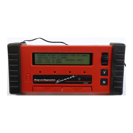
INTRODUCTION INTRODUCTION NOTE: For simplicity, the Snap-on Scanner, MT-2500, the Sun Scanner and the Sun PDL-1000 are designated as the SCANNER in this manual. Figure 1: SCANNER, CARTRIDGE & CABLES CARTRIDGE € COMMUNICATION CABLE, RS 232 UNIVERSAL DATA CABLE, VEHICLE... - Page 9 INTRODUCTION BATTERY INSTALLATION An alkaline battery is required for proper Scanner operation. Standard or “Heavy- Duty” 9-Volt batteries do not provide enough power. For longer battery life, install a lithium 9-Volt battery as a replacement. 1: Grasp the left handgrip and carefully pull it outwards and backwards from the Scanner.
-
Page 10: Operation Overview
INTRODUCTION OPERATION OVERVIEW The Scanner Code-Reading functions and other tests available depend on the type of vehicle tested and the cartridge. Basic operation consists of the following: 1: Insert the Cartridge. If the cartridge does not seat smoothly and easily, do not force it. Remove it from the scanner and be sure the edge connector fingers are not bent. -
Page 11: Operation
OPERATION OPERATION 1: SCANNER START-UP If no primary cartridge is inserted, using either the “Quick ID” button or the vehicle connector to apply power to the scanner. The following display check should be displayed: nnnnnnnnnnnnnnnnnnnnnnnnnnnnnnnnnnn nnnnnnnnnnnnnnnnnnnnnnnnnnnnnnnnnnn nnnnnnnnnnnnnnnnnnnnnnnnnnnnnnnnnnn nnnnnnnnnnnnnnnnnnnnnnnnnnnnnnnnnnn The 4 LEDs should be on and two beeps should be heard during the display check. -
Page 12: Vehicle Selection
OPERATION VEHICLE SELECTION Because manufacturers’ midyear changes in engine computer systems may affect data transmission, always enter a new identification when testing a different vehicle. This is true even when two different vehicles are the same year and model and have the same engine and accessory installations. -
Page 13: Abbreviations
OPERATION ABBREVIATIONS ABBR DESCRIPTION ABBR DESCRIPTION One Barrel Carburettor 4-Cylinder Line Engine Two Barrel Carburettor Multi-Point Injection Air Conditioning Passenger Air Bag Automatic Transmission Passenger Pretensioner Central Point Injection Passenger Side Air Bag Drivers Air Bag Rear Left, (Wheel) Driver Pretensioner Rear Right, (Wheel) Drivers Side Air Bag 4-Cylinder Transverse Engine... -
Page 14: 4: Main Menu
OPERATION 4: MAIN MENU All programs can be accessed from the “Main Menu”. To return to the “Main Menu” from the various sub-menus press N several times. The available items in the “Main Menu” are dependant on: • Vehicle system to be tested •... - Page 15 OPERATION FUNCTIONAL TESTS For direct activation of peripheral parts, connected to the ECU. The actuator test menu displays all relevant available actuators. The Functional Tests are also used for Ignition and Fuel adjustments on some vehicles. OTHER SYSTEMS (IF APPLICABLE) Use this item to select another system (if fitted) to be tested, e.g.
-
Page 16: 5: Codes And Data
OPERATION 5: CODES AND DATA The “Codes & Data” selection from the “Main Menu” is available on most vehicles. In this mode, the Scanner reads data available on the ECU data stream, including trouble codes that may be present in the ECU memory. This means that “Codes &... -
Page 17: Data Lists
OPERATION DATA LISTS When Y is pressed from the “Main Menu” to select “Codes & Data”, the Scanner displays the ECU data list and information about trouble codes, if applicable: RPM 1000 O2 (mV) 658 BATT (V) 13.5 ** USE CUSTOM DATA LIST FOR FASTER REFRESH ** 14 COOLANT TEMPERATURE SENSOR COOLANT ( COOLANT (V) -
Page 18: Scanner Communication
OPERATION SCANNER COMMUNICATION The “Codes & Data” selection from the “Main Menu” requires that the Scanner communicates with the ECU. The following must be performed: • Connect the Scanner to the Diagnostic Connector. • Turn the ignition ON. If one of these functions is selected before doing these things, the Scanner displays a message similar to this: WAITING FOR ECU TO COMMUNICATE WITH SCANTOOL. -
Page 19: Fixing, Holding And Recording
OPERATION If a code is present, it is displayed along with a description, like the following: RPM 1000 O2 (mV) 658 BATT (V) 13.5 ** USE CUSTOM DATA LIST FOR FASTER REFRESH ** 14 COOLANT TEMPERATURE SENSOR COOLANT ( COOLANT (V) 5.00 If two or more codes are present, scroll the thumbwheel to see any other codes and the start of the data list. -
Page 20: Holding A Frame Of Data
OPERATION HOLDING A FRAME OF DATA To capture and hold a single frame of data press Y while in “Codes & Data”. A data frame is one data transmission cycle from the ECU data stream. When holding a frame, all data readings are locked at the last readings before pressing Y, the top line of the display looks like this: RPM 1000 O2 (mV) 658... - Page 21 OPERATION RPM 1000 O2 (mV) 658 BATT (V) 13.5 The frame counter in the upper left advances to show the recording speed of the movie. When the Scanner records 25 % of the frames after the trigger point, the display top line changes to: RPM 1000 O2 (mV) 658 BATT (V) 13.5...
-
Page 22: 6: Codes & Data "Exit" Menu
OPERATION 6: CODES & DATA “EXIT” MENU This menu is displayed after leaving the “Codes & Data” list by pressing N. Select the desired menu item using the thumbwheel and press Y. NOTE: The “Exit Menu” may be different from the illustration. Press “N” again to return to the “Main Menu”. -
Page 23: Arm Movie
OPERATION Refer to the “Custom Setup” section of this manual for instructions about setting the Scanner for printer communication. Refer to the “Remote Printer Setup” section of the Reference Manual for information on setting-up the printer. All print-outs of a screen or a frame include the vehicle identification. After connecting the printer and ensuring that communication is set correctly, scroll the thumbwheel to “Print Screen”... -
Page 24: Led Menu
OPERATION RPM 1000 O2 (mV) 658 BATT (V) 13.5 Pressing N aborts the “Arm Movie” selection and returns to the “Exit” menu. If a previous movie was recorded, it is erased. The current movie can be reviewed but only from the 0 Trigger point and negative frames. 5: Press Y to trigger the movie after returning to the data mode. -
Page 25: Clear Ecu Codes
OPERATION Line 3 must be release before Line 2 can be released. Scroll to “Release Line 3” and press Y. Again, it will automatically return to the previous data mode. The “Exit” menu will be displayed with “Release Line 2” and “Fix Line 3” choices. If Line 2 is released, the “Exit”... -
Page 26: Custom Data List
OPERATION The Scanner returns to the previous “Codes & Data” mode, and line 3 of the display indicates that codes are cleared by displaying the message: NO CODES PRESENT. If the code-clearing operation fails for any reason, the previous codes will reappear at the top of the data list when returning to “Codes &... -
Page 27: 7: Review Movie
OPERATION 7: REVIEW MOVIE “Review Movie” appears on the “Main Menu” only if a movie has been recorded. Subsequent movie recording or entering a new vehicle identification overwrites or erases any previous movie. The movie can be up to 101 frames long: •... - Page 28 OPERATION A positive number for a frame after the trigger point. RPM 1234 O2 (mV) 689 BATT (V) 13.5 A negative number for a frame before the trigger point: RPM 1234 O2 (mV) 689 BATT (V) 13.5 Press Y to switch the thumbwheel function back and forth from scrolling frames to scrolling data within a frame.
-
Page 29: 8: Review Movie Exit Menu
OPERATION 8: REVIEW MOVIE EXIT MENU Press N to leave the Review Movie. The “Review Movie Exit” menu is displayed: >RESUME [PRESS N FOR MAIN MENU] PRINT SCREEN LED MENU PRINT FRAME This “Exit” menu is similar to the “Exit” menu for data viewing modes, except that “Arm Movie”, “Custom Data List”... -
Page 30: 9: Functional Tests
OPERATION 9: FUNCTIONAL TESTS “Functional Tests” gives the operator the possibility to activate components of the engine management system, such as Actuator Tests, Wiggle Tests, Output State Tests, etc. The number of tests depends on the primary cartridge, some examples are listed below: REVIEW ECU ID Information concerning the ECU is displayed in this test. -
Page 31: 10: Other Systems
OPERATION 10: OTHER SYSTEMS Use this item to select another system (if installed) to be tested, e.g. Engine, Anti- lock brakes, Air Bag, etc. However, actually selecting a different system will cause any stored data to be lost and a warning message will be displayed: SELECTING ANOTHER SYSTEM WILL CAUSE ANY STORED INFORMATION TO BE LOST, PRESS “N”... -
Page 32: Air Bag
OPERATION AIR BAG 1: Select “Air Bag” and press Y, a message will be displayed giving information about connecting an adaptor, press Y to continue. The “Main Menu” will be displayed. 2: Select “Codes Only” and press Y, the following “Code List” should be displayed, (example): NOTE: Some Systems may also display “Data”. -
Page 33: 11: Custom Setup
OPERATION 11: CUSTOM SETUP Allows the selection of certain Scanner functions for a customized setup: • Set parameters for communication between Scanner and a PC or printer. • Change English/Metric units. • Assign functions to the 4 LED’s or Right / Left Hand Drive Setup •... -
Page 34: Led Menu
OPERATION LED MENU Parameters can only be selected to be On/Off, or Open/Closed or Rich/Lean. This is useful for a quick check when driving or accelerating to check whether a switch or an actuator is operating correctly under normal driving conditions. To change the LED assignment, scroll to select the choice and press Y to set. -
Page 35: Remote Terminal Communication
REMOTE TERMINAL COMMUNICATION REMOTE TERMINAL COMMUNICATION The primary cartridges for the Scanner also can display test information on some other remote terminals. This communication feature is designed to work with equipment that operates in a VT100 format, which is a common industry standard for terminal operation. - Page 36 REMOTE TERMINAL COMMUNICATION 5: Use either the scanner controls or the terminal keyboard to operate all scanner functions. The Y and N keys on the keyboard correspond to the Y and N buttons on the scanner. The up-arrow and down-arrow keys on the keyboard correspond to the forward and backward directions of the thumbwheel.
-
Page 37: Troubleshooter
TROUBLESHOOTER TROUBLESHOOTER The Troubleshooter system simplifies the time consuming part of diagnosis. The Troubleshooter system provides on-line diagnostic information on the scanner screen as you work on a vehicle. It greatly minimizes the time-consuming chore of digging through bulky repair manuals for the information you need to solve a problem. - Page 38 TROUBLESHOOTER 9: Press N to leave the Troubleshooter menu and return to the primary cartridge MAIN MENU. The primary cartridge and the Troubleshooter cartridge work interactively. You can switch back and forth between the Troubleshooter menu and the primary cartridge MAIN MENU to perform any available diagnostic reading or test function.
-
Page 39: Troubleshooting
TROUBLESHOOTING TROUBLESHOOTING 1: START-UP PROBLEMS If the display does not light up when using the Quick ID button or connecting the Scanner to vehicle power, check the following: • The Scanner battery, located under the left handgrip. For a blown cigarette lighter fuse in the vehicle. •... -
Page 40: 4: Communication Problems / Status
TROUBLESHOOTING 4: COMMUNICATION PROBLEMS / STATUS When the Scanner is unable to establish communication with the ECU in the vehicle under test, or when the communication is interrupted, a message will be displayed. Wait to see whether the communication is established again or interrupted. Press N to abort. -
Page 41: Glossary
GLOSSARY GLOSSARY Code A numerical code or an alphanumerical code, generated by the vehicle control system to indicate that a fault has occurred in a particular sub-system, circuit or component. Codes & Data The test mode that displays trouble codes and engine computer data parameters for those vehicles that transmit ECU data. - Page 42 - 38 -...
-
Page 43: Appendix: The Colour Graphing Scanner
Appendix: The Colour Graphing Scanner Appendix: The Colour Graphing Scanner ________________________ 39 Introduction ....................40 Baud rate settings ..................40 Layout ......................41 Understanding the Display ..............41 Entering Graphing Mode ................42 Locking a parameter ................43 Unlocking a parameter ................43 Capturing data in Graphing Mode ............ -
Page 44: Introduction
Appendix: The Colour Graphing Scanner Introduction NOTE: Only the additional key and functions are explained here. For standard operating features, refer to the Scanner section and the Primary Cartridge operator’s manual. The Colour Graphing Scanner has the ability to select and graph parameters from a ‘live data’... -
Page 45: Layout
Appendix: The Colour Graphing Scanner Layout Following elements are specific to the Colour Graphing Scanner. All other buttons and their functionality are described in the Scanner section. Refer to Figure 2. 1 -Connection for battery charger 2 -’Graphing’ button Figure 2 Understanding the Display Refer to Figure 1. -
Page 46: Entering Graphing Mode
Appendix: The Colour Graphing Scanner NOTE: If the ECU is operating in a default mode (substituting pre- programmed values to control the actuators due to absent or unreliable input signals), these default values transmit on the data stream of some vehicles. the graph plots trends of the parameter signals and is not intended to be used for measuring voltage level, frequency, amplitude, or other signal char- acteristics. -
Page 47: Locking A Parameter
Appendix: The Colour Graphing Scanner • Press the Y button to enter the Graphing Mode. The program will setup the communication. Figure 5 should appear. If not, refer to the Trouble Shoot- ing section at the end of this appendix. Figure 5 Live data parameters for the vehicle under test will be displayed, for a sample refer to Figure 6. -
Page 48: Resetting Min/Max Parameter Values
Appendix: The Colour Graphing Scanner To capture data: • press the Graphing button. The displayed data is now captured and held. Refer to Figure 8. Figure 8 appears on the display to indicate that no “live” data is shown. To return to “live” data: •... -
Page 49: Trouble Shooting The Colour Graphing Scanner
Appendix: The Colour Graphing Scanner Trouble Shooting the Colour Graphing Scanner Only Trouble Shooting specific to the Colour Graphing Scanner is described here. Baud rate setting error. the baud rate is not set to 4800, 9600 or 19200 and if the Graphing Mode is entered and the Y button is pressed, the display will equal Figure 11 (in stead of Figure 5). -
Page 50: Communication Error
Appendix: The Colour Graphing Scanner Communication error If a severe communication error happens, the display equals Figure 13. Figure 13 • Disconnect and reconnect the Data Cable to remove power. This will reset the Colour Graphing Scanner. -46-... -
Page 51: Internal Battery Pack
Appendix: The Colour Graphing Scanner Internal Battery Pack The internal battery pack(part number EAA0278B04A) is used only to power the Scanner during the Quick ID procedure. During normal operation, the Scanner will receive power through the connection to the vehicle you are testing. Depending upon use and care, the long-life battery pack can last up to several years. -
Page 52: Battery Replacement Procedures
Appendix: The Colour Graphing Scanner Battery Replacement Procedures To replace the battery: Grasp the left handgrip and carefully pull it outward and backward off of the Scanner body. Do not remove the metal bail from the handgrip. Slip the battery pack out of the Scanner body and separate the wire con- nector, Figure 15. -
Page 53: Appendix: The Emb Cartridge
Appendix: The EMB Cartridge The EMB cartridge. The Scanner can work either with: the Primary Cartridge (for communication with the car) plus an (optional) expert system (Trouble Shooter) cartridge, or the Extended Memory Board (EMB) Cartridge plus the Vehicle Communication Interface (VCI) Cartridge. The advantages of the EMB Cartridge over the Primary Cartridge are: The EMB can contain software for either one car brand (previously referred to as Primary Cartridge) or a range of car brands for easier and faster... - Page 54 Appendix: The EMB Cartridge Installing additional Primary Software on the EMB. This procedure is described in the Operator’s Manual of the ScanBay. The ScanBay can download software onto the EMB Cartridge in order to update the software or expand the amount of Primaries installed. 1: Scanbay -50-...
Need help?
Do you have a question about the MT-2500 and is the answer not in the manual?
Questions and answers