Table of Contents
Advertisement
Advertisement
Table of Contents

Related Manuals for Snap-On ETHOS Tech


Summary of Contents for Snap-On ETHOS Tech
- Page 1 User Manual ZEESCGB321A Rev. A...
- Page 2 Legal Information Trademarks Snap-on is a trademark, registered in the United States and other countries, of Snap-on Incorporated. This publication contains many Snap-on Incorporated trademarks, including but not limited to Snap-on and ETHOS. All other marks are trademarks or registered trademarks of their respective holders.
-
Page 3: Safety Information
Safety Information READ ALL INSTRUCTIONS For your own safety, the safety of others, and to prevent damage to the product and vehicles upon which it is used, it is important that all instructions and safety messages in this manual and the accompanying Important Safety Instructions manual be read and understood by all persons operating, or coming into contact with the product, before operating. - Page 4 Safety Information Safety Signal Words Safety Signal Words All safety messages contain a safety signal word that indicates the level of the hazard. An icon, when present, gives a graphical description of the hazard. Safety Signal words are. Indicates an imminently hazardous situation which, if not avoided, will result in death or serious injury to the operator or to bystanders.
-
Page 5: Table Of Contents
Contents Safety Information ........................ ii Chapter 1: Using This Manual .....................3 Content ...........................3 Conventions..........................3 Terminology ........................3 Symbols ...........................3 Bold Text ..........................4 Notes and Important Messages ..................4 Hyperlinks ........................4 Procedures........................4 Chapter 2: Introduction......................5 Control Buttons........................6 Data and Power Connections....................7 Battery Cover and Stand ......................7 Power Sources ........................8 Batteries ...........................8 AC/DC Power Supply.......................8... - Page 6 Vehicle Identification ......................21 Connecting the Data Cable ....................22 System and Test Selection ....................23 Exiting Scanner ........................35 Chapter 5: OBD-II/EOBD ....................36 Basic Operations ........................36 Screen Layout and Toolbar Controls ................36 Connecting the Data Cable ....................36 Saving and Reviewing Data Files ..................36 OBD-II/EOBD Menu ......................
-
Page 7: Chapter 1 Using This Manual
Using This Manual Chapter 1 1.1 Content This manual contains basic operating instructions and is structured in a manner to help you become familiar with your diagnostic tool features and perform basic operations. The illustrations in this manual are intended as reference only and may not depict actual screen results, information, functions or standard equipment. -
Page 8: Bold Text
Using This Manual Conventions 1.2.3 Bold Text Bold emphasis is used in procedures to highlight selectable items such as control buttons, icons and menu options. Example: Press the OK button. 1.2.4 Notes and Important Messages The following messages are used. Notes A NOTE provides helpful information such as additional explanations, tips, and comments. -
Page 9: Chapter 2 Introduction
Introduction Chapter 2 This multi-function diagnostic tool allows you to communicate with various OBD-II/EOBD vehicle control systems (e.g. engine, transmission, antilock brake system (ABS), body, instrument cluster, etc) to: • Perform OEM specific functional tests and relearn procedures • Retrieve and clear diagnostic trouble codes (DTCs) •... -
Page 10: Control Buttons
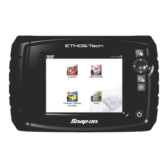
Introduction Control Buttons 2.1 Control Buttons There are four “push type” control buttons and one “thumb pad rocker type” multi-directional button located on the right side of the Diagnostic Tool. All other Diagnostic Tool operations are controlled through the touch screen. Figure 2-1 Front view Item Button... -
Page 11: Data And Power Connections
Introduction Data and Power Connections 2.2 Data and Power Connections Connectors and jacks for data communication cables and the AC/DC Power Supply are located on the top of the Diagnostic Tool. Figure 2-2 Top view Item Description Mini USB Jack - USB cable connection used to connect the Diagnostic Tool to a personal computer. -
Page 12: Power Sources
Introduction Power Sources An adjustable hand strap and a collapsible stand, that attach to the back of the Diagnostic Tool housing, are available as optional equipment. The padded hand strap threads through mounting slots on the Diagnostic Tool housing. Velcro fasteners hold the strap in place and allow for quick adjustments. -
Page 13: Technical Specifications
Introduction Technical Specifications 2.5 Technical Specifications Item Description / Specification Touch Screen Resistive Touch Panel 5.6 inch diagonal, LCD TFT Display 640 x 480 resolution SWVGA 24 bit color Batteries (6) 1.5V AA Operating System Processor Motorola DC Jack Operating 8 to 32VDC Voltage Width... -
Page 14: Chapter 3 Basic Operation And Navigation
Basic Operation and Chapter 3 Navigation This chapter describes basic Diagnostic Tool operation, navigation, screen layout, icon functions, and screen messages. Before you operate the Diagnostic Tool, make sure new batteries are installed or the Diagnostic Tool is powered by the AC power supply. 3.1 Installing the Batteries The six AA batteries provided with your Diagnostic Tool kit must be installed before using the tool. -
Page 15: Turning On/Off And Emergency Shutdown
Basic Operation and Navigation Turning On/Off and Emergency Shutdown Figure 3-2 Installing batteries (battery cover removed) 3. Install the battery cover. 3.2 Turning On/Off and Emergency Shutdown The following sections describe how to turn the Diagnostic Tool on and off and how to perform an emergency shutdown. -
Page 16: Emergency Shutdown
Basic Operation and Navigation Basic Navigation 3.2.3 Emergency Shutdown IMPORTANT: Using the emergency shutdown procedure while communicating with the vehicle ECM may lead to ECM problems on some vehicles. During normal operation turn the Diagnostic Tool off using the Turning Off procedure above. The emergency shutdown procedure should only be used If the Diagnostic Tool does not respond to navigation or the control buttons, or exhibits erratic or abnormal operation. -
Page 17: Title Bar
Basic Operation and Navigation Basic Navigation 3.3.2 Title Bar The title bar at the top of the screen provides basic information about current Diagnostic Tool operating conditions. Title bar options vary depending upon vehicle make and model, what function is active, what test is being performed, or what menu is selected. The title bar contains information only, there are no selectable items. -
Page 18: Home Screen Icons
Basic Operation and Navigation Basic Navigation 3.3.3 Home Screen Icons Each available Diagnostic Tool function is represented by a icon on the home screen. The table below provides descriptions of the icon functions. Select an icon from the Home screen to launch a function. You can also use the control buttons to activate a function, a yellow border around the icon indicates it is highlighted, or in focus. -
Page 19: Common Toolbar Control Icons
Basic Operation and Navigation Basic Navigation 3.3.4 Common Toolbar Control Icons Common control icon functions are described in the following table. Specific function control icons are described in their applicable chapters. Displayed control icons vary depending on the active function or test. Select a control icon on a screen to activate a control function. You can also use the control buttons to activate a function, a yellow border around the icon indicates it is highlighted, or in focus. -
Page 20: Scroll Bar
Basic Operation and Navigation Basic Navigation 3.3.5 Scroll Bar A vertical scroll bar appears along the right-hand edge of the screen when additional data expands above or below what is currently on the screen (Figure 3-4). Figure 3-4 Scroll bar 1—... -
Page 21: System Messages
Basic Operation and Navigation Screen Messages 3.4 Screen Messages 3.4.1 System Messages There are four types of system messages that may be displayed: Message Type Description Loading and connecting messages display when the Diagnostic Tool is performing an Loading and internal operation, such as loading a database, establishing communications with the Connecting vehicle, or initiating a test. -
Page 22: Data Cable Connection
Basic Operation and Navigation Data Cable Connection 3.5 Data Cable Connection Connection of the data cable to the Diagnostic Tool and vehicle DLC is required for Scanner and OBD-II/EOBD testing. Depending on the vehicle, the supplied DA-4 data cable may be used alone or may require optional adapters. -
Page 23: Chapter 4 Scanner
Scanner Chapter 4 This chapter describes the basic operation of the Scanner function. The Scanner icon is located on the Home screen. The Scanner function allows your Diagnostic Tool to communicate with the electronic control systems of a vehicle. This allows you to retrieve diagnostic trouble codes (DTCs), view PID data and perform diagnostic tests. -
Page 24: Scanner Control Icons
Scanner Scanner Demonstration Program 4.1.2 Scanner Control Icons The scanner toolbar contains control icons. Control icons may vary depending on the active function or test. A yellow frame surrounding an icon (highlighted), indicates it is selected. Other control icons (not shown) are described in Common Toolbar Control Icons‚... -
Page 25: Scanner Operation
Scanner Scanner Operation 4.3 Scanner Operation Launching Scanner opens a menu list of vehicle manufacturers and begins the process by identifying the vehicle being tested. After the vehicle is identified, a vehicle system is selected and then a specific test or function is selected to allow you to retrieve diagnostic trouble codes (DTCs), view and save PID data, or perform diagnostic tests. -
Page 26: Connecting The Data Cable
Scanner Scanner Operation 2. Select the vehicle manufacturer from the list. A model year menu displays. 3. Select the vehicle year from the menu. A list of vehicle types or models displays. Several selections may be required to complete the vehicle identification, follow the screen prompts to enter the required information. -
Page 27: System And Test Selection
Scanner Scanner Operation 4.3.3 System and Test Selection After a vehicle is selected, a menu of available systems is displayed. Select a system to continue. Figure 4-4 Available systems list NOTE: Only the systems available for testing on the identified vehicle are included in the list. After a system is selected and the Diagnostic Tool establishes communication with the vehicle, a menu, of available tests is displayed. - Page 28 Scanner Scanner Operation Main menu options vary slightly by the year, make, and model of the test vehicle. The main menu may include: • Codes Menu—displays diagnostic trouble code (DTC) records from the vehicle electronic control module. Selecting may open a submenu of viewing options. Clear Codes—erases DTC records and other data from the ECM.
- Page 29 Scanner Scanner Operation Codes Menu This selection may appear as Codes, Codes Menu, Codes Only, Codes (No Data), Service Codes or something similar on the menu. Selecting opens a list of viewing options that includes: • Display Codes • Clear Codes‚...
- Page 30 Scanner Scanner Operation To clear codes: 1. Select Clear Codes from the Codes Menu. A confirmation message displays. 2. Make sure any conditions shown on the confirmation message are met, then select Yes. A “codes cleared” message displays once the operation is complete. 3.
- Page 31 Scanner Scanner Operation Up to three parameters can be locked, or fixed, at the top of the list. Locked parameters do not change as you scroll through the parameter list. The Lock/Unlock icon on the toolbar selects which parameters are fixed (see Locking Parameters‚...
- Page 32 Scanner Scanner Operation Changing Screen Views Selecting the View icon opens a drop-down menu of options: • PID List 1 Graph • 2 Graph • 4 Graph • The PID (parameter identification) List view is a 2-column display with the name of the parameters in the left column and their current values in the right column (Figure 4-7).
- Page 33 Scanner Scanner Operation Locked parameters display as the top frames on the main body of the display screen, as well as at their usual position within the data list (Figure 4-9). A lock icon appears to the left of the parameter name to indicate it is locked.
- Page 34 Scanner Scanner Operation Setting Trigger Levels The trigger icon allows you to configure the Diagnostic Tool to automatically save PID data from buffer memory to a file when a parameter value crosses a threshold. When triggering is armed, a "Trigger event" pauses data collection and saves data to a file. Selecting the Trigger icon opens a menu that includes: Set Trigger—establishes upper and lower signal values to initiate an event capture for the •...
- Page 35 Scanner Scanner Operation A lower trigger level line now appears at the mid-point of the graph. 6. Select the plus (+) and minus (–) icons on the toolbar, or use the up b and down d arrow buttons to position the lower trigger level line to where you want it on the graph. 7.
- Page 36 Scanner Scanner Operation To save data: Select Save. • A save dialog box displays while data is being saved. The data is saved when the message box disappears. Figure 4-11 Save dialog box Saving Screens The Shortcut button can be programmed to save a snapshot of a visible screen as a bitmap file, Configure Shortcut Button‚...
- Page 37 Scanner Scanner Operation 1— Step Back 4— Cursor 2— Step Forward 5— Counter (current position / total) 3— Record Figure 4-12 2. Scroll up or down to review the list of data. 3. Select the desired control icon to move forward or back incrementally in the selected direction. To resume: Select the Record icon.
- Page 38 Scanner Scanner Operation Functional Tests The Functional Tests selection is used to access vehicle-specific subsystem tests. Available tests vary by manufacturer, year, and model. Only the tests available for the identified vehicle display in the menu. There are several types of functional tests: •...
-
Page 39: Exiting Scanner
Scanner Exiting Scanner 4.4 Exiting Scanner Scanner function remains open as long as there is an active communication link with the vehicle. You must interrupt this communication link in order to exit from tests and power down the Diagnostic Tool. A warning message displays if you attempt to shut down while the Diagnostic Tool is communicating with the vehicle. -
Page 40: Chapter 5: Obd-Ii/Eobd
OBD-II/EOBD Chapter 5 This chapter describes the basic operation of the OBD-II/EOBD function. The OBD-II/EOBD icon is located on the Home screen. The OBD-II/EOBD function allows you to access “generic” OBD-II/EOBD data. Generic OBD-II/EOBD data is data limited to emission related diagnostics such as: •... - Page 41 OBD-II/EOBD OBD-II/EOBD Menu Start Communication Use the following procedure to begin an OBD-II/EOBD test session: To perform an OBD-II/EOBD Test: 1. Connect the data cable to the test vehicle. 2. Select Start Communications from the OBD-II/EOBD menu. A series of messages are displayed indicating automatic detection of vehicle type (12 or 24 V) has occurred and then the detected controllers are displayed.
- Page 42 OBD-II/EOBD OBD-II/EOBD Menu IMPORTANT: All service modes are not supported by all vehicles, so the available menu selections will vary. Figure 5-2 Service mode menu 4. Select a test to continue. Readiness Monitors Use this menu item to check the readiness of the monitoring system. Monitors not supported will display “not supported”.
- Page 43 OBD-II/EOBD OBD-II/EOBD Menu ($01) Display Current Data Use this test to display the serial data transmitted by the selected vehicle electronic control module (ECM). The main body of the screen has two columns; the left-hand column is a description of the parameter and the right-hand column is the parameter value or state. Viewing options and operations are the same as the Scanner function, see Data Display‚...
- Page 44 OBD-II/EOBD OBD-II/EOBD Menu To clear emission related Data: 1. Select Clear Emissions Related Data from the menu. A confirmation message displays to help prevent loss of any vital data (Figure 5-4). Figure 5-4 Clear codes confirmation message 2. Continue from the confirmation message. The screen updates several times as ECM memory is erased, then a “data has been cleared”...
- Page 45 OBD-II/EOBD OBD-II/EOBD Menu ($07) DTCs Detected During Last Drive This test opens a record of any DTCs that set during the last completed drive cycle. Select to open the DTC list. ($08) Request Control of On-board System This service enables bidirectional control of the ECM. This service allows the Diagnostic Tool to control the operation of an on-board system, test, or component.
- Page 46 OBD-II/EOBD OBD-II/EOBD Menu Manual Protocol Selection Communication protocol is a standardized way of transferring data between an ECM and a Diagnostic Tool. Global OBD may use the following communication protocols: • ISO 15765-4 (CAN) • ISO 27145 (WWHOBD CAN) ISO J1939 (CAN) •...
-
Page 47: Chapter 6 Previous Vehicles And Data
Previous Vehicles and Data Chapter 6 This chapter describes the basic operation of the Previous Vehicles and Data function. The Previous Vehicles and Data icon is located on the Home screen. This function allows you to select recently tested vehicles and access saved data files. 6.1 Previous Vehicles and Data Menu The following options are available from the Previous Vehicles and Data menu: •... -
Page 48: View Saved Data
Previous Vehicles and Data Previous Vehicles and Data Menu To select from the vehicle History: 1. Select Previous Vehicles and Data from the Home screen. 2. Select Vehicle History from the menu. A list of up to 25 previously tested vehicles displays. Each vehicle is given a unique file name. Scroll to view the entire list. -
Page 49: Delete Saved Data
Previous Vehicles and Data Previous Vehicles and Data Menu 6.1.3 Delete Saved Data This menu option is used to permanently erase saved files from memory. To delete a saved file: 1. Select Previous Vehicles and Data from the Home screen. 2. -
Page 50: Chapter 7 Tools
Tools Chapter 7 This chapter describes the basic operation of the Tools function. The Tools icon is located on the Home screen. This function allows you to configure Diagnostic Tool settings to your preferences. 7.1 Tools Menu The following options are available from the Tools menu: •... -
Page 51: Connect-To-Pc
Tools Tools Menu 7.1.1 Connect-to-PC Connect-to-PC connects your Diagnostic Tool to your personal computer using a USB cable. Using the ShopStream Connect™ PC software allows you to transfer files, download software upgrades, save data files on your PC and more. See Software Updating and ShopStream Connect‚... -
Page 52: System Information
Tools Tools Menu 7.1.3 System Information System Information displays important information such as: • Patent information • Software version numbers Diagnostic Tool serial number • Software upgrade program expiration date • Figure 7-2 System information To display the System information screen: 1. - Page 53 Tools Tools Menu System Settings Selecting System Settings opens a menu with two options; Display and Date & Time. Either selection opens an additional menu. Display options include: • Brightness‚ on page 50,—adjusts the intensity of the screen back lighting. •...
- Page 54 Tools Tools Menu Brightness Selecting this option opens the brightness setting screen for adjusting the back lighting of the display (Figure 7-4). Figure 7-4 Brightness setting Each push of the Plus and Minus icons, or the up (b) and down (d) arrows, incrementally changes the back lighting up or down respectively.
- Page 55 Tools Tools Menu Color Theme This option allows you to select between a white and black background for the screen. The black background can be beneficial when working under poor lighting conditions. Selecting opens a menu with two choices: Day Theme (white background) and Night Theme (black background).
- Page 56 Tools Tools Menu Font Type This option allows you to select between standard and bold faced type for the display screen. Bold type makes screen writing more legible under poor lighting or bright sunlight conditions. Figure 7-6 Bold type on a black background Selecting opens a menu with two choices: Normal Font and Bold Font.
- Page 57 Tools Tools Menu Touch Screen Calibration Calibrating the touch screen maintains the accuracy of the touch-sensitive display. IMPORTANT: To avoid serious damage to the Diagnostic Tool, always complete the touch screen calibration sequence once it has begun. Never turn off the Diagnostic Tool while a screen calibration is in process.
- Page 58 Tools Tools Menu Time Zone This option opens a menu of time zone settings. Scroll to highlight, then select the local time zone. The display returns to the Settings menu once a time zone is selected. IMPORTANT: A notice that saved files may be overwritten momentarily displays whenever an option that alters the internal clock setting is selected (Figure 7-8).
- Page 59 Tools Tools Menu 4. Select the up (+) icon on the screen or press the up (b) button to incrementally increase the number in the highlighted field. Select the down (–) icon on the screen or press the down (d) button to incrementally decrease the number.
- Page 60 Tools Tools Menu Configuring Scanner This option allows you to change the scanner display to toggle scales on and off. Scales are the graduations and values that display on the horizontal axis at the base of the parameter graphs. The waveform fills the entire graph area with scales switched off. Figure 7-10 Scales hidden To change hide/show scales: 1.
- Page 61 Tools Tools Menu Configure Units Selecting opens a dialog box that allows you to choose between US customary or metric units of measure for temperature, vehicle speed, air pressure, and other pressures. Figure 7-11 Configure units menu To change the units setup: 1.
-
Page 62: Chapter 8 Software Updating And Shopstream Connect
Software upgrades are provided periodically and are downloaded and installed by SSC on to your ETHOS Tech. When your ETHOS Tech is connected to a PC using SSC, the SSC software will automatically check for upgrades and (if an upgrade is available) provide installation instructions. - Page 63 Software Updating and ShopStream Connect Software Upgrades Figure 8-1 Typical Update window 4. After the download is complete, the installation confirmation message is displayed. Follow the onscreen instructions and then select Continue to proceed with the software upgrade installation (Figure 8-2).
- Page 64 The Programming status window is displayed until programming is completed (Figure 8-3). IMPORTANT: Do not disconnect the ETHOS Tech during programming. Figure 8-3 5. After the download is complete, the installation confirmation message is displayed. Select Continue to complete the software upgrade installation.
-
Page 65: Chapter 9 Maintenance
Maintenance Chapter 9 9.1 Cleaning and Inspecting When using the Diagnostic Tool perform the following tasks to keep it in top shape: Check the housing, wiring, and connectors for dirt and damage before and after each use. • At the end of each work day, wipe the Diagnostic Tool housing, wiring, and connectors clean •... -
Page 66: Replacing The Batteries
Maintenance Battery Service • Do not expose the batteries to excessive physical shock or vibration. Keep batteries pack out of reach of children. • Do not use a battery that appears to have suffered abuse or damage. • Store batteries in a cool, dry, well ventilated area. •... -
Page 67: Disposing Of The Batteries
Maintenance Battery Service Figure 9-2 Battery cover removed 3. Observing proper polarity (shown on the battery slots), install six new AA batteries. IMPORTANT: Your Diagnostic Tool can be damaged if the battery polarity is incorrect. Refer to the diagram in the battery compartment on the rear of the tool for correct battery polarity. -
Page 68: Index
Index AC/DC power supply 8 Generic functions 24 Actuator tests 24 Home screen 14 Battery 8 Disposal 63 Handling 61 Identifying a test vehicle 21 Replacing 62 Information tests 34 service 61 – Brightness, adjusting 50 Buttons Control 6 Locking parameters 28 Changing screen views 28 Manual conventions Cleaning 61... - Page 69 Index Saved vehicle data 44 Saving 32 Variable control tests 34 Scanner 19 Vehicle history 44 Actuator tests 24 Clear codes 24 Codes menu 24 Communication protocol 42 Connecting 18 Custom data list 27 Data display 29 Demonstration program 20 Exiting 35 Functional tests 24 Generic functions 24...
Need help?
Do you have a question about the ETHOS Tech and is the answer not in the manual?
Questions and answers