Table of Contents
Advertisement
Advertisement
Table of Contents

Related Manuals for Snap-On BK7000


Summary of Contents for Snap-On BK7000
- Page 1 BK7000 High Definition Videoscope Operating Manual 1 ...
-
Page 2: General Safety Information
General Safety Information Read and understand all instruc ons. Failure to follow all instruc ons listed below may result in electric shock, fire and/or serious personal injury. Work Area Safety Keep your work area clean and well lit. Clu ered b enches and dark areas may cause • accidents. Do not operate electrical devices or video scope t ool in explosive atmospheres, such as in • the presence of flammable liquids, gases, or heavy dust. Electrical devices or visual inspec on tools create sparks which may ignite the dust or ... - Page 3 Personal Safety • Stay alert, watch what you are doing and use common sense. Do not use video scope while red or under the influence of drugs, alcohol, o r medica ons. A moment of ina en on while opera ng tools may result in serious personal injury. Do not overreach. Keep proper foo ng and balance at all mes. Proper foo ng and balance • enables be er control of the tool in unexpected situa ons. Use safety equipment. Always wear eye protec on (users and bystanders). Dust mask, non‐ • skid safety shoes, hard hat, or hearing pro t ec on must be used for appropriate condi ons. Use proper accessories. Do not place this product on any unstable cart or surface. • •...
- Page 4 To reduce the risk of serious injury, read these precautions carefully before using the battery charger o r battery. A/C Power Supply Do not probe A/C power supply with conduc ve objects. Shor ng of ba ery terminals • may cause sparks, burns or electrical shock. • Do not use A/C power supply if damaged. A damaged A/C power supply increases the risk of electrical shock. • Use an appropriate power source. Do not a empt to use a step‐up transformer or an engine generator. Doing so may cause damage t o the A/C power supply of the BK7000 resul ng i n electrical shock, fire or burns. • Do not allow anything to cover the A/C power supply while in use. Proper ven la on is required for correct opera on of the A/C power supply. Allow a minimum of 4” (10 cm) of clear‐ ance around the charger for proper ven la on. Unplug the A/C power supply when not in use. Reduces the risk of injury to children • 4 ...
- Page 5 • Unplug the A/C power supply from outlet before a emp ng any maintenance or cleaning. Reduces the risk of electrical shock. • Do not use A/C power supply in a damp, wet o r explosive environment. Do not expose to r ain, snow or dirt. Contaminants and moisture increase the risk of electrical shock. • Do not open the A/C power supply or BK7000 housings. Have repairs performed only at authorized loca ons. (See Snap‐on Service Center). Do not carry the A/C power supply by power cord. Reduces the risk of electrical shock. • 5 ...
- Page 6 F (45 degrees C). Store BK7000 in temperatures above ‐4°F (‐20°C) and below 140°F (60°C). Storage for a long me at temperatures above 95°F (35°C) will reduce the capacity of the BK7000. It is recommended to store the BK7000 at 77°F (25°C) to maximize ba ery life. Proper care will prevent serious damage to the ba ery. Improper ...
- Page 7 Battery Safety continued • If the BK7000 is damaged, do not plug the A/C power supply into it. Do not a empt to charge. Never disassemble the BK7000 unit. There are no user‐serviceable parts inside. • • Disassembling the BK7000 may cause electrical shock or personal injury. Avoid contact with fluids leaking from the BK7000 unit. Fluids may cause burns or skin irrita on. Thoroughly rinse with water in case of accidental contact with fluid. Consult doctor if fluid comes into contact with eyes. 7 ...
- Page 8 Video Scope Use and Care • Use video scope only as directed. Do not operate the inspection unit unless the owner’s manual has been read and proper training has been completed. • Do not immerse the handheld display unit in water. Store in a dry place. Such measures reduce the risk of electric shock and damage. The imager head and the cable are water resis‐ tant when the unit is fully assembled, but the video display unit/handle is not. • Do not use the camera if condensation forms inside the lens. Let the water evaporate before using again. • Do not use tool if ON/OFF switch is not properly w orking. Any tool that cannot be controlled with the switch is dangerous and must be repaired. • Store idle equipment out of the reach of children and other untrained persons. Equipment is dangerous in the hands of untrained users. • Maintain the video scope with care. Properly maintained tools are less likely to cause injury. 8 ...
- Page 9 If unit is dropped, check for breakage of parts, and any other conditions that may affect • the tool’s operation. If damaged, have the tool ser‐ viced before using. Many accidents are caused by poorly maintained tools. • Use only accessories that are recommended by the manufacturer for your tool. Accessories that may be suitable for one tool may become hazardous when used on another tool. • Dry your hands before turning the unit ON or OFF. Protect against excessive heat. The product should be situated away from heat sources • such as radiators, heat registers, stoves or other p roducts (including amplifiers) that produce ...
- Page 10 Service • Do not a empt to take any pieces of this unit apart unless directed to by this manual. Follow instruc ons for changing accessories. Accidents are caused by poorly maintained • equipment. Provide proper cleaning. Do not use acetone to clean the unit. Instead, use isopropanol. • • Gently clean the LCD with a dry cloth. Stop using the unit if it starts smoking or emit‐ ng noxious fumes. • Refer video scope to qualified service personnel • under any of the following conditions: – If liquid has been spilled or objects have fall e n into product; – If product does not operate normally by following the opera ng instruc ons; – If the product has been dropped or damaged in anyway ...
- Page 11 – When the product exhibits a dis nct change i n performance. If you have any questions regarding the service or repair of this machine, call or write to the appropriate r epair center location (see "Snap‐on Service Center Locations”). Technical questions can be directed to our toll free number at 1‐877‐765‐7665 Monday through Friday 6:30 am to 5:00 pm Central Time (U.S. customers only). 11 ...
-
Page 12: Specific Safety Information
Specific Safety Information Read this operator's manual carefully before using. Failure to understand and follow the contents of this m anual may result in electrical shock, fire and/or se v ere personal injury. FCC Statement This device complies with Part 15 of the FCC Rules. Operation is subject to the following two conditions: This device may not cause harmful interference. This device must accept any interference received, including interference that may cause undesired opera on. NOTE! This equipment has been tested and found to comply with the limits for Class A digital devices, pursuant to Part 15 of the FCC rules. These limits are designed to provide reasonable protec on against harmful interference in a residen al ... - Page 13 interference to radio communica ons. However, there is no guarantee that interference will not occur in a par cular installa on. If this equipment does cause harmful interference to radio or television r ecep on, which can be determined by turning the equipment off and on, the user is encouraged to try to correct the interference by one or more of the following measures: Reorient or relocate the receiving antenna. – – Increase the separa on between the equipment and receiver. – Consult the dealer for help. Use of shielded cable is required to comply with Class A limits in Subpart B of Part 15 of the FCC rules. Do not make any changes or modifications to the equipment. This device complies with Part 15 of the FCC Rules and with Industry Canada license‐exempt RSS standard(s). Operation is subject to the following two c onditions: (1) This device may not cause harmful interference, and (2) This device must accept a ny interference received, including reference that may ...
- Page 14 expressly approved by the party responsible for compliance could void the user's authority to operate the equipment. This Class A digital device complies with Canadian ICES‐003. 14 ...
- Page 15 Video Scope Safety • Do not place tool into anything or anywhere that m ay contain a live electrical charge. FOR WALLS: For inspec ng inside walls, be sure to shut off the circuit breaker to the • whole house before using the tool behind any of the walls • FOR PIPES: If you suspect a metal pipe could contain an electrical charge, have a qualified electrician check the pipe before using the tool. Ground circuits, in some cases, can be returned to cast iron pipes and cause them to b e charged. ...
-
Page 16: Product Description
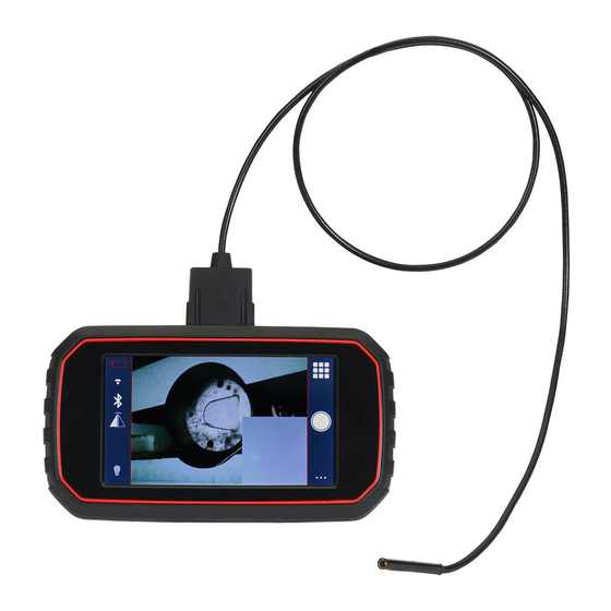
Product Description The BK7000 digital high defini on videoscope provides true HD video thanks to it high resolu on imager paired with the high resolu on LCD screen. The 5” screen makes any under the hood job easy to see… The BK7000 features a capaci ve touch screen display and dual view picture in picture imager… 16 ... - Page 17 Included with the BK7000: BK7000 handheld unit 5.5mm Dual view HD PiP imager (a ached to unit) Quick start guide Power supply with 4 interchangeable power source adapters USB‐C to USB‐A power cord BK7000 travel case 17 ...
-
Page 18: Specifications
Specifications Getting Started Descrip on The BK7000 video scope displays live color video from an imaging sensor and lighting source connected to a flexible dual view imager cable. The unit is capable of capturing still images and full‐ motion video, along with audio. It can be used to look into tight spots and beam back real‐time video to a true high definition color LCD. 18 ... - Page 19 Specifica ons Total Weight........2.25 lbs (800g) DISPLAY UNIT: Power Supply........ Internal Li‐Ion Battery, 3.7V, 2600 mAh, 9.6 watt‐hours Charge time........ 1.25 hours Charger Input........ 5V DC, 1. Amp Length.......... 1.28" (32.5mm) Width.......... 6.75" (171.4mm) Height..........3.77" (100mm) Built‐in Camera........ 1280 x 720 HD Fixed focust Screen Resolution...... 1280 x 720 with LED backlight 5.0" (12.7 cm) Capacitive Color Touchscreen LCD Audio Input........Built‐in Microphone Audio Output........Built‐in Speaker 19 ...
- Page 20 DISPLAY UNIT Specifica ons: Run‐time on battery...... 3 hours (approximately) Wireless interface......Wi‐Fi ‐ 802.11n Wireless range........ 50 ft (10m) Operating Temperature.... 32°F to 86°F (0°C to 30°C) (Batteries will not charge above 113°F (45°C)) Storage Temperature...... ‐4°F to 140°F (‐20°C to 60°C ) 77°F (25°C) is ideal for maximum battery life. Relative Humidity......5% to 90% non‐condensing 20 ...
- Page 21 IMAGER: Length.......... 36 in (0.91m) Forward Camera/Side Camera Field of View........ approximately 62° diagonal Optimal Focal Range....... 0.5” to 12” (12cm to 30.5cm) Resolution........ 1280 x 720 Operating Temperature.... 32°F to 140°F (0°C to 60°C) Storage Temperature...... ‐4°F to 140°F (‐20°C to 60°C) Relative Humidity...... 5% to 90% non‐condensing Water Resistance...... Imager to 10' (3m) water depth (when assembled) 21 ...
- Page 22 A/C Power Supply: Input Voltage........100‐240VAC, 50‐60Hz 0.6Amp Maximum inrush current .... 30A @ 115VAC, 60A @ 230VAC Output voltage ........ 5V DC 2.6Amp Max No Load Standby power .... <0.3W Operating Temperature.... 32°F to 104°F (0°C to 40°C) Storage Temperature...... 14°F to 167°F (‐10°C to 75°C) Relative Humidity...... 20% to 80% non‐condensing NOTE! The charger and internal batteries are not compatible with any other Snap‐on Li‐Ion Batteries and chargers. 22 ...
-
Page 23: Available Accessories
Available Accessories BK7000‐38FV ‐ 3.8mm diameter, 36 inch long forward view imager BK7000‐38SV ‐ 3.8mm diameter, 36 inch long Side view imager The 3.8mm diameter imagers are specifically designed to be able to pass through the glow plug port in a diesel engine. The side view will provide a high definition image of the cylinder walls and image of the valve profile. The forward facing imager will provide a clear image of the piston face and combustion cup. 23 ... - Page 24 Feature Outlines (diagram of the unit with descriptions of hardware functions/features) 24 ...
- Page 25 Introduction Do not operate the video scope in explosive atmospheres, such as in the presence of flammable liquids, gases, or combustible dust. This unit create sparks which may ignite the fumes or dust. No responsibility will be taken by Snap‐on for any resulting damage to the unit or to the operator if it is used with corrosive or dangerous or explosive gas and dust mixtures. 25 ...
- Page 26 When using the video scope at the inspection site, make certain that you and the work area is safe for the unit to be used. This is not classified as flameproof or intrinsically safe; therefore, it must not be used where explosion hazard may exist. For complete details on product and operator safety, review the General Safety Information section. 26 ...
- Page 27 Setup Battery Requirements/Warnings Daily, before use, inspect the BK7000 and A/C Power Supply and correct any problems. Set up charger according to these procedures to reduce the risk of injury from electrical shock, fire, and other causes and prevent tool and system damage. Before using the BK7000 for the first time, allow it charge for at least 1.5 hours to ensure that the batteries are fully charged. 27 ...
- Page 28 Assembling the Charger The charger is supplied with a selection of power outlet adaptors for use in multiple countries. Before first use, select the appropriate adaptor for your country and attach it by aligning the male notches on the back of the adapter with the female notches on the power block then twist clockwise, the adapter will click and lock into place. To switch adapter, push and hold down on the locking tap, located on the power block, and twist counterclockwise to release/open, see Figure 2. Lock Figure 2: Assemble/Disassemble Charger 28 ...
- Page 29 Charging the Unit With dry hands, insert the USB‐C end of the power cord into the charging port as shown in Figure 3 and insert the USB‐A end into the power block. Ensure that the correct adapter is fitted into the power block and insert the charger into a suitable power outlet to charge unit. When charging is complete remove USB‐C Figure 3: Charging 29 ...
- Page 30 The BK7000 will only charge the batteries if the temperature is between 0°C and 45°C (32°F and 113°F). Outside of this temperature range the BK7000 may continue to operate but the batteries will not charge, and the Charge Status LED will be off. When the battery is fully charged, status LED will be illuminated solid green. There is no risk of over‐charging the battery. When the battery has been fully charged, the charger automatically switches to retention charging. 30 ...
- Page 31 Be sure to inspect the power cord and power block for any damages. If there are any broken or worn parts, exposed wires or any damage of this nature, do not use until parts are replaced. Be sure to keep the unit clean; free of oils, grease and dirt, as described in the Maintenance section. This will prevent the unit from slipping out of your hands and will allow proper unit ventilation. 31 ...
-
Page 32: Charging Status
Charging Status Charge Status LED Status Battery Status Not Charging LED is OFF No power to battery Charging Green (blinking) Battery is low Fully Charged Green (solid) Battery is fully charged 32 ... - Page 33 Battery/unit error The LED light on the unit change color and pattern depending on the status of the battery. See Figure 4 Not Charging Red (blinking) for LED location 33 ...
- Page 34 Disconnecting and Connecting Imagers To switch imagers, first, turn the unit off. Then pinch and hold the sides of the connector and pull imager out of the unit. To connect an imager be sure to align the male notches on the imager connector with the female notches on the unit and insert, see Figure 4. 34 Figure 4: Disconnect/Connect Imager...
- Page 35 Powering the Unit The BK7000 unit is ready to use directly out of the box. No assembly process is required. The unit can be powered on by pressing and holding the power button for 2 seconds. The unit will power on and the indicator light will illuminate. To turn the unit off, press and hold the power button for 2 seconds and the unit will power off. 35 ...
-
Page 36: Operation
Operation The BK7000 requires an initial registry setup out of the box. Once the unit is set up and registered, it will be ready use. 36 ... - Page 37 Power on the unit, once the splash screen disappears, the language selection page will appear. Scroll through the languages and select one by clicking on the language bar. The blue arrow on the language bars indicates “next page”, see Figure 5. 37 ...
- Page 38 38 Figure 5: Language Selec on...
- Page 39 Set Date/Time After the language has been set, the next page will prompt you to select the time zone. The time zone can be set to your choice or skipped and set later, see Figure 6. Important: Setting the time zone allows for a time and date stamp on important documents and submissions. 39 ...
- Page 40 Keep pink circle but remove pink line. Figure 6: Time Zone Selec on 40 ...
- Page 41 41 ...
- Page 42 WiFi Setup 42 ...
- Page 43 WiFi can be set by selecting a secured network and entering a 批注 [SW1]: Is this a requirement? What is the network is not secure? password. The WiFi setup can be skipped and set later, see Figure 7. Once the password is entered, click on “JOIN” in the upper right 43 ...
- Page 44 corner. Important: The time zone will properly be retrieved and displayed only when the unit is connected to WiFi. 44 Figure 7: WiFi Setup...
- Page 45 Register Device On the next page enter in your name, phone number and email address. Then click on “REGISTER” to use the tool, see Figure 8. 45 Figure 8: Final Registra on Step...
- Page 46 Using the BK7000 Home screen button functionalities Ba ery Status Media Gallery Wi‐Fi Status Bluetooth UI Flip Image Capture LED Control Se ng Menu 46 ...
-
Page 47: Led Control
LED control Touch the light bulb icon to make the LED Slide appear 47 ... - Page 48 Battery icon on screen shows the statuses of the battery life Battery Icon Icon Color/Pattern Battery Life Status Green (solid) Fully charged battery < 25% battery life Red (blinking) remaining 48 ...
- Page 49 Taking a picture Once satisfied with what is displayed on the screen, click on the shutter button, refer to Figure X for icon descriptions. The screen will flash black, indicating that the picture was successfully taken. To view the screen in full display before taking the picture, tap the screen once; to re‐display screen icons, tap the screen once again. 49 ...
-
Page 50: Taking A Video
Taking a video Click on the menu button in the bottom, right corner and select the “Video” mode under the “Camera Settings”. Then click the “X” in the top, left corner of the menu to exit and return to the home screen. In video mode, the shutter button will be displayed as a red record button with a white circle around it. To start recording, click on the record button, the video record time will start and be displayed on the left side of the screen underneath the battery icon. To stop recording click on the record button again, the record time will stop. 50 ... - Page 51 Settings Menu – Photos, Video Photo or Video select Camera select Diagnos c Filter select 51 ...
-
Page 52: Settings Menu
Settings Menu Auto shutdown se ng Screen Brightness Control On screen Time and Date 52 ... - Page 53 Settings Menu Speaker Volume Control Microphone On/Off Memory Capacity 53 ...
- Page 54 Settings Menu Wi‐Fi Status Bluetooth Status Language Selec on Speaker Volume 54 ...
- Page 55 Settings Menu Time & Date Se ng Firmware update Licensing Agreement 55 ...
- Page 56 Viewing pictures and videos To view pictures and videos, click on the gallery icon. Media Gallery 56 ...
- Page 57 On the next screen you can view and playback pictures and videos by clicking on them. To delete items out of the library, click on the “Select” button in the … corner, then tap on each picture or image, a check mark will appear in the selection box of each item, click “Delete”. 57 ...
- Page 58 Audio Annotation 58 ...
- Page 59 Annotating a Picture 59 ...
-
Page 60: Renaming A File
Renaming A File 60 ... - Page 61 Transferring photos and videos to computer Connect the unit to a computer using the USB-C to USB power cord that is included with the unit. Once the external drive appears on the computer, click on it. The pictures and videos can be transferred and saved to the file of your choice on the PC.
- Page 62 Connecting to Wi‐Fi The WiFi can be enabled and disable in the main menu. Click on the main menu button, scroll down to “Connectivity”, click on “Wifi”. 62 ...
-
Page 63: Connecting To Bluetooth
Connecting to Bluetooth 63 ... - Page 64 Connecting to Bluetooth 2 64 ...
- Page 65 Connecting to Bluetooth 3 65 ...
- Page 66 Resetting BK7000 to factory settings Click on the “reset” button next “Factory Reset”. A pop up box with appear asking “Are you sure”, click on “yes”. The unit screen will turn black then restart. Once the unit reboots up, you will be prompted to ...
-
Page 67: Troubleshooting
Troubleshooting POSSIBLE SYMPTOM SOLUTION REASON The imager is not fully inserted into Connect imager securely to Display unit does not the unit unit display image from Damaged imager Replace imager imager Imager camera covered Clean imager lens Battery is critically Charge unit until battery Units will not switch on low indicator light is solid green 67 ... - Page 68 Contact a nearby service Battery does not hold Faulty battery center and start the return charge process. Check power supply Power supply is connection and secure to not plugged in power source. Damaged power Units will not charge supply/power cord Replace power supply. Operating Place unit in temperature temperature is environment between 32°F below or above and 113°F, allow to cool or 32°F and 113°F warm, then charge the unit. Image on display is Processor locked frozen up Cycle power 68 ...
- Page 69 Contact a nearby service Charging LEDs flashing Faulty battery/unit center and start the return red process. 69 ...
-
Page 70: Warranty
Warranty Limited Two (2) Year Warranty Snap‐on Tools Company (the “Seller”) warrants only to the original purchaser that under normal use, care and service, the Equipment (except as otherwise provided herein) shall be free from defects in material and workmanship for two years from the date of original invoice. SELLER’S OBLIGATIONS UNDER THIS WARRANTY ARE LIMITED SOLELY TO THE REPAIR OR, AT SELLER’S OPTION, REPLACEMENT OF EQUIPMENT OR PARTS WHICH TO SELLER’S SATISFACTION ARE DETERMINED TO BE DEFECTIVE AND WHICH ARE NECESSARY IN SELLER’S JUDGMENT, TO RETURN THIS EQUIPMENT TO GOOD OPERATING CONDITION. NO OTHER WAR‐ RANTIES, EXPRESS OR IMPLIED OR STATUTORY, INCLUDING WITHOUT LIMITATION ANY IMPLIED WARRANTY OR MERCHANTABILITY OR FITNESS FOR A PARTICULAR PURPOSE, SHALL APPLY AND ALL SUCH WARRANTIES ARE HEREBY EXPRESSLY DISCLAIMED. This warranty does not cover (and separate charges for parts, labor and related expenses 70 ... - Page 71 shall apply to) any damage to, malfunctioning, in operability or improper operation of the Equipment caused by, resulting from or attributable to (A) abuse, misuse or tampering;(B) alteration, modification or adjustment of the Equipment by other than Seller’s authorized representatives; (C) installation, repair or maintenance (other than specified operator maintenance) of the Equipment or related equipment, attachments, peripherals or optional features by other than Seller’s authorized representatives; (D) improper or negligent use, application, operation, care, cleaning, storage or handling; (E) fire, water, wind, lightening or other natural causes; (F) adverse environmental conditions, including, without limitation, excessive heat, moisture, corrosive elements, or dust or other air contaminants, radio frequency interference, electric power failure, power line voltages beyond those specified for the Equipment, unusual physical, electrical or electromagnetic stress and/or other condition outside of Seller’s environmental specifications;(G) use of Equipment in combination or connection with other equipment, attachments, supplies or consumable not manufactured or supplied 71 ...
- Page 72 by Seller; or (H) failure to comply with any applicable federal, state or local regulation, requirement or specification governing emission analyzers and related supplies or consumables. Repairs or replacements qualifying under this Warranty will be performed on regular business days during Seller’s normal working hours within a reasonable time following purchaser’s request. All requests for Warranty service must be made during the stated warranty period. This Warranty is nontransferable. 72 ...
-
Page 73: Snap-On Service Center Locations
Snap‐on Service Center Locations Eastern Repair Center (USA) Snap‐on Tools (Australia) Pty Ltd 6320 Flank Drive National Distribution Centre Harrisburg, PA 17112 USA Unit 6/110 Station Road Toll Free # ‐ (USA only): (800)‐ PO Box 663 848‐5067 Sven Hills, NSW 1730 Australia Telephone: (717) 652‐7914 Telephone: (61) 2‐9837‐9100 Fax: (717) 652‐7123 Fax: (61) 2‐9624‐2578 email: sota.webmasters@snapon.com 73 ... - Page 74 Northern Repair Center (USA) Snap‐on Tools Singapore PTE, Ltd. 3011 E. RT 176, Dock 8 25 Tagore Lane #01‐01 Crystal Lake, IL 60014 Singapore 787602 Toll Free # ‐ (USA only): (877) Telephone: +(65) 6451‐5570 777‐4412 Fax: +(65) 6451‐5574 Telephone: (815) 479‐6850 email: esale.sg@snapon.com Fax: (815)479‐6857 Internet: http://snapon.com.sg Western Repair Center (USA) Snap‐on Tools Japan, K.K. 3602 Challenger Way Snap‐on, Bahco, and Cartec Carson City, NV 89706 USA Also serving Taiwan and Micronesia Toll Free # ‐ (USA only): (888) (Distribution Center and Technical Repair 762‐7972 Center) Telephone: (775) 883‐8585 2‐1‐6 Shinkiba, Koto‐ku, Fax: (775) 883‐8590 Tokyo, 136‐0082 JAPAN 74 ...
- Page 75 Telephone: +81 3 5534 1280 Fax: +81 3 5534 1284 email: SOJ‐INFO@snapon.co.jp OEM, National Accounts, GSA Distribution: +81 3 5534 1300 Industrial: +81 3 5534 1281 BAHCD: +81 3 5534 1301 Technical Repair Center: +81 3 5534 1289 Snap‐on UK Repair Centre Snap‐on Tools of Canada Repair Center Snap‐on Tools, Ltd. 7403 48th St. S.E. Telford Way, Kettering Calgary, Alberta T2C 4H6 CANADA Northants, NN16 8UN ENGLAND Toll Free #: (866) 824‐0525 Telephone: 01536 413855 Telephone: (403) 720‐4525 Fax: 01536 410740 Fax: (403) 720‐4524 75 ...
- Page 76 email: canadianquestions@snapon.com 76 ...
- Page 77 Caution: Note : Cet appareil est conforme à la Partie 15 des règlements de la FCC et aux normes RSS de l’Industrie du Canada. Son fonctionnement est soumis aux deux conditions suivantes : (1) cet appareil ne doit pas causer des interférences nuisibles, et (2) cet appareil doit accepter toute interférence reçue, y compris les interférences qui peuvent provoquer un fonctionnement indésirable. ...
- Page 78 The device has been evaluated to meet general RF exposure requirement. The SAR limit of USA (FCC) is 1.6 W/kg averaged over one gram of tissue. Device types BK7000 with BK7000 (FCC ID: 2AADC‐BK7) has also been tested against this SAR limit. The highest reported SAR values for body‐worn is 0.61W/kg. This device was tested for typical body‐worn operations with the back of the handset kept 0mm from the body. The use of accessories that do not satisfy these requirements may not comply with FCC RF exposure requirements, and should be avoided. For 5150-5250 and 5725-5850 frequency band, Operations in the 5150-5250 and 5725-5850 band are restricted to indoor usage only.
Need help?
Do you have a question about the BK7000 and is the answer not in the manual?
Questions and answers