Table of Contents
Advertisement
Available languages
Available languages
Quick Links
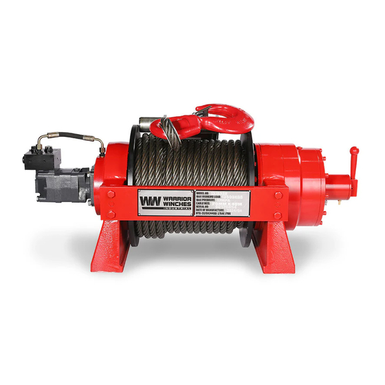
WINCH MODELS:
13JR03H, 15JR03H
20JR03H, 25JR03H
30JR03H
SAVE THESE INSTRUCTIONS. This manual contains important safety precautions which should be read and understood before operating the product. Failure to do so could result in
serious injury. Specifications, descriptions and images in this manual are as accurate as known at the time of publication, but are subject to change without notice.
JR HYDRAULIC WINCH
OWNERS MANUAL
Register your product online
ENGLISH
DEUTSCH
ENGLISH
FRANÇAIS
POLSKI
Doc-rev 20240201
Advertisement
Table of Contents

Related Manuals for Warrior Winches JR Series


Summary of Contents for Warrior Winches JR Series
- Page 1 JR HYDRAULIC WINCH OWNERS MANUAL ENGLISH WINCH MODELS: DEUTSCH ENGLISH 13JR03H, 15JR03H FRANÇAIS 20JR03H, 25JR03H 30JR03H POLSKI Register your product online Doc-rev 20240201 SAVE THESE INSTRUCTIONS. This manual contains important safety precautions which should be read and understood before operating the product. Failure to do so could result in serious injury.
-
Page 2: Getting To Know Your Winch
INTRODUCTION WINCH MANUAL INTRODUCTION GETTING TO KNOW YOUR WINCH Congratulations on your purchase of a winch. We design and build Your winch is a powerful piece of machinery. It is important that you winches to strict specifications and with proper use and maintenance your understand the basics of its operation and specifications so that winch should bring you years of satisfying service. -
Page 3: Important Safety Instructions
IMpORTANT SAFETY INSTRUCTIONS WINCH MANUAL IMpORTANT SAFETY INSTRUCTIONS DANGER DANGER When re-spooling the cable Ensure that the cable spools in the under-wind position with the cable entering the drum from the bottom, not the top. To re-spool correctly, and while wearing gloves, DO NOT EXCEED RATED CAPACITY. - Page 4 IMpORTANT SAFETY INSTRUCTIONS WINCH MANUAL WARNING NOTICE Keep children away. Children must never be allowed in the work area, The vehicle engine should always be kept running during winching Do not let them handle machines, tools, extension cords or operate operation to minimize battery drain and maximize power and speed this tool.
-
Page 5: Winch Assembly And Mounting
IMpORTANT SAFETY INSTRUCTIONS WINCH MANUAL CAUTION WARNING Always re-spool cable neatly after any operation this will avoid any Do not operate tool if under the influence of alcohol or drugs. winch cable misalignment for the next use Read warning labels on prescription to determine if your judgment or reflexes are impaired while taking drugs. -
Page 6: Installation
HYDRAULIC pRINCIpAL CHART AND INSTALLATION: WINCH MANUAL Hydraulic flow control valves are adept at controlling the flow of these – Mounting The Balance Valve: The balance valve supplied should liquids from the pumps to cylinders and motors. Their primary function is be already connected to motor. - Page 7 HYDRAULIC pRINCIpAL CHART AND INSTALLATION: WINCH MANUAL Winch Hydraulic Motor Balance Valve ENGLISH Selector Valve Relief Valve Oil Tank Engine Control Valve Winch Motor Check Valve Engine Pump Relief Cooler Valve Oil Filter Oil Tank...
-
Page 8: Operation
OpERATION WINCH MANUAL OpERATION CAUTION Always leave at least five turns of cable on the drum. Review Winch Air + Manual mixed clutch Safety Warnings and Precautions, before continuing. 3. Engage clutch: Rotate clutch lever in the direction shown (Manual) or turn off the air supply (Air Operated) 4. -
Page 9: Cable Assembly Replacement
MAINTENANCE pRECAUTIONS WINCH MANUAL Storage 6. The opening pressure of the balancing valve must be 0.1-0.4Mpa higher than the brake, or the winch will shake when lowering it down. The Hydraulic winch should be stored in the warehouse where the air is Our company has tested hoisting and adjusted balancing valves for dry and no corrosive gas. -
Page 10: Troubleshooting
WARRANTY* address and contact number, (4) copy of the original purchase receipt or BPE Limited can arrange a suitable collection method (Charges apply). BPE Limited are the sole distributors of these WARRIOR WINCHES and associated brands/equipment. Warranty Exclusions The Warranty does not cover the cost of labour or transportation/shipping BPE Limited (“seller”... -
Page 11: Specifications
SpECIFICATIONS WINCH MANUAL SpECIFICATIONS 13JR03H Rated line pull lbs (kg) 29700 (13500) Motor displacement 200ml/r Oil flow 15~75L/min Pressure 19Mpa Gear reduction ratio 37.8:1 Cable (Dia.× L) Ø0.79”×131’ (Ø20mm×40m) Drum size(Dia.× L) Ø7.46 “×13.39”(Ø189.5mm×340mm) Mounting bolt pattern 20.55 “×7.09”×11.02” (522mm×180mm×280mm) 8-M20 41.06”×19.69”×16.14”... - Page 12 SpECIFICATIONS WINCH MANUAL SpECIFICATIONS 15JR03H Rated line pull lbs (kg) 33000 (15000 ) Motor displacement 250ml/r Oil flow 10~120L/min Pressure 20Mpa Gear reduction ratio 40.6:1 Cable (Dia.× L) Ø0.87"×164' (Ø22mm×50m) Drum size(Dia.× L) Ø8.27 "×13.39"(Ø210mm×340mm) Mounting bolt pattern 20.55 "×7.09"×11.02" (522mm×180mm×280mm) 8-M20 42.13”×19.69”×16.34”...
- Page 13 SpECIFICATIONS WINCH MANUAL SpECIFICATIONS 20JR03H Rated line pull lbs (kg) 44000 (20000) Motor displacement 315ml/r Oil flow 10~120L/min Pressure 20Mpa Gear reduction ratio 36:1 Cable (Dia.× L) Ø1.02"×147' (Ø26mm×45m) Drum size(Dia.× L) Ø8.27"×13.39"(Ø210mm×340mm) Mounting bolt pattern 20.94"×6.3"×11.02" (532mm×160mm×280mm) 8-M24 46.61”×20.2”×16.54” Overall dimensions (L×W×H) 1184mm ×513mm ×420mm Net weight Ibs(kg)
- Page 14 SpECIFICATIONS WINCH MANUAL SpECIFICATIONS 25JR03H Rated line pull lbs (kg) 55000 (25000) Motor displacement 315ml/r Oil flow 10~120L/min Pressure 18Mpa Gear reduction ratio 53:1 Cable (Dia.× L) Ø1.18"×164' (Ø30mm×50m) Drum size(Dia.× L) Ø10.63 "×14.2"(Ø270mm×360mm) Mounting bolt pattern 24 "×6.7"×12.2" (610mm×170mm×310mm) 8-M27 49.65”×25.2”×21.3”...
- Page 15 SpECIFICATIONS WINCH MANUAL SpECIFICATIONS 30JR03H Rated line pull lbs (kg) 66000 (30000) Motor displacement 500ml/r Oil flow 10~120L/min Pressure 16Mpa Gear reduction ratio 53:1 Cable (Dia.× L) Ø1.26"×147' (Ø32mm×45m) Drum size(Dia.× L) Ø10.63 "×14.2"(Ø270mm×360mm) Mounting bolt pattern 24 "×6.7"×12.2" (610mm×170mm×310mm) 8-M27 50.24”×25.2”×21.3”...
- Page 16 EINFüHRUNG WINCH MANUAL EINFüHRUNG LERNEN SIE IHRE WINDE KENNEN Herzlichen Glückwunsch zum Kauf Ihrer Winde. Wir entwickeln und bauen Ihre Winde ist ein leistungsstarkes Gerät. Es ist wichtig, dass Winden nach strengen Vorgaben. Bei richtiger Anwendung und Wartung Sie die Funktionsweise und die technischen Einzelheiten dieser wird Ihre Winde Ihnen jahrelang gute Dienste leisten.
-
Page 17: Wichtige Sicherheitshinweise
WICHTIGE SICHERHEITSHINWEISE WINCH MANUAL WICHTIGE SICHERHEITSHINWEISE GEFAHR Beim Aufwickeln muss darauf geachtet werden, dass das Seil mit GEFAHR dem Seileinlauf unten aufgewickelt wird und von unten, nicht von oben, in die Trommel eintritt. Tragen Sie beim Aufwickeln des Seils DIE NENNTRAGLAST DARF NICHT ÜBERSCHRITTEN WERDEN. - Page 18 WICHTIGE SICHERHEITSHINWEISE WINCH MANUAL HINWEIS HINWEIS Die Winde und alle mit ihr verwandten Gerätetypen haben eine Jede Winde, die auf irgendeine Weise beschädigt scheint, abgenutzt bestimmte Nennkapazität, wenn die erste Seillage auf die Trommel ist oder nicht normal funktioniert, MUSS umgehend außer Betrieb gewickelt wird.
- Page 19 WICHTIGE SICHERHEITSHINWEISE WINCH MANUAL VORSICHT WARNUNG Pflegen Sie diese Winde mit Sorgfalt. Halten Sie dieses Werkzeug Stellen Sie sicher, dass die Winde ordnungsgemäß mit einer Struktur trocken und sauber für eine bessere und sicherere Leistung. Befolgen (oder einem Fahrzeug) verschraubt ist, die die maximale Nennlast der Sie die Anweisungen zum Schmieren und Wechseln von Zubehör.
- Page 20 HYDRAULISCHES HAUpTDIAGRAMM UND INSTALLATION: WINCH MANUAL – Montage des Ausgleichsventils: Das mitgelieferte VORSICHT Ausgleichsventil sollte bereits mit dem Motor verbunden sein. Stellen Sie sicher, dass die Installationsrichtung des Ausgleichsventils der Das Windenseil muss unter einer Belastung von mindestens 10 % des hydraulischen Haupttabelle entspricht.
- Page 21 HYDRAULISCHES HAUpTDIAGRAMM UND INSTALLATION: WINCH MANUAL Hydraulische Steuerventile sind eine wesentliche Komponente zur „O“ -Typ: Alle Ölanschlüsse sind geschlossen und das System entlädt Optimierung der Systemleistung. Sie werden verwendet, um die sich nicht. Hydraulikzylinder mit Öl gefüllt, glatt vom Stillstand bis zum Durchflussrate und den Druck des Hydrauliköls zu regulieren, wenn es Start.
- Page 22 EINFüHRUNG WINCH MANUAL Winde Hydraulikmotor Ausgleichsventil Motor Auswahlventil Überdruckventil Öltank Motor Regelventil Winde Motor Rückschlagventil Motor Pumpe Überdruckventil Kühler Ölfilter Öltank...
- Page 23 BETRIEB DER LUFTKUppLUNG WINCH MANUAL BETRIEB DER LUFTKUppLUNG 2. Greifen Sie die Kabelkonfektion und ziehen Sie das Kabel auf die gewünschte Länge, dann befestigen Sie es an dem zu ziehenden Gegenstand. Luft- und manuelle Mischkupplung VORSICHT Lassen Sie immer mindestens fünf Windungen des Kabels auf der Trommel.
-
Page 24: Wartung
VORSICHTSMASSNAHMEN FüR DIE WARTUNG WINCH MANUAL 2. Erweitern Sie die Kabelkonfektion auf ihre volle Länge. Beachten das Balanceventil selbst einzustellen, indem Sie eine Fachperson Sie, wie das vorhandene Kabel mit der Trommel verbunden ist. oder einen Kundendienstmitarbeiter verwenden. 3. Entfernen Sie die alte Kabelkonfektion und befestigen Sie eine 7. -
Page 25: Fehlerbehebung
VORSICHTSMASSNAHMEN FüR DIE WARTUNG WINCH MANUAL Lagerung Die hydraulische Winde sollte in dem Lager gelagert werden, in dem die Luft trocken und kein korrosives Gas ist. Stellen Sie es nicht unter eine hohe Temperatur von50°C oder einer Umgebung von-20°C für eine langfristige Lagerung, falls die Alterung von Dichtungsteilen beschleunigt wird. -
Page 26: Garantie
GARANTIE* WINCH MANUAL GARANTIE* BPE Limited ist nicht für indirekte Schäden oder Folgeschäden verantwortlich oder haftbar. Bei derartigen Folgeschäden kann es sich BPE Limited ist der alleinige Vertriebspartner von WARRIOR- unter anderem um entgangene Gewinne, Nutzungsausfall, Ausfallzeiten WINDEN. oder Schäden an der Ausrüstung anderer Personen handeln. BPE Limited („Verkäufer“... -
Page 27: Technische Daten
TECHNISCHE DATEN WINCH MANUAL TECHNISCHE DATEN 13JR03H Bemessungslinienzug 29700 (13500) Motorverschiebung 200ml/r Ölfluss 15~75L/min Druck 19Mpa Untersetzungsverhältnis 37.8:1 Kabel (Durchmesser × L) Ø0.79”×131’ (Ø20mm×40m) Trommelgröße(Dia.× L) Ø7.46 “×13.39”(Ø189.5mm×340mm) Muster der Befestigungsschrauben 20.55 “×7.09”×11.02” (522mm×180mm×280mm) 8-M20 41.06”×19.69”×16.14” Gesamtabmessungen (L×B×H) 1043mm ×500mm ×410mm Nettogewicht Ibs(kg) 771.6 (350) Durchfluss und Geschwindigkeit (erste Schicht) - Page 28 TECHNISCHE DATEN WINCH MANUAL TECHNISCHE DATEN 15JR03H Bemessungslinienzug 33000 (15000 ) Motorverschiebung 250ml/r Ölfluss 10~120L/min Druck 20Mpa Untersetzungsverhältnis 40.6:1 Kabel (Durchmesser × L) Ø0.87"×164' (Ø22mm×50m) Trommelgröße(Dia.× L) Ø8.27 "×13.39"(Ø210mm×340mm) Muster der Befestigungsschrauben 20.55 "×7.09"×11.02" (522mm×180mm×280mm) 8-M20 42.13”×19.69”×16.34” Gesamtabmessungen (L×B×H) 1070mm ×500mm ×415mm Nettogewicht Ibs(kg) 903.8 (410) Zug und Druck (erste Schicht)
- Page 29 TECHNISCHE DATEN WINCH MANUAL TECHNISCHE DATEN 20JR03H Bemessungslinienzug 44000 (20000) Motorverschiebung 315ml/r Ölfluss 10~120L/min Druck 20Mpa Untersetzungsverhältnis 36:1 Kabel (Durchmesser × L) Ø1.02"×147' (Ø26mm×45m) Trommelgröße(Dia.× L) Ø8.27"×13.39"(Ø210mm×340mm) Muster der Befestigungsschrauben 20.94"×6.3"×11.02" (532mm×160mm×280mm) 8-M24 46.61”×20.2”×16.54” Gesamtabmessungen (L×B×H) 1184mm ×513mm ×420mm Nettogewicht Ibs(kg) 1135 (515) Zug und Druck (erste Schicht) Durchfluss und Geschwindigkeit (erste Schicht)
- Page 30 TECHNISCHE DATEN WINCH MANUAL TECHNISCHE DATEN 25JR03H Bemessungslinienzug 55000 (25000) Motorverschiebung 315ml/r Ölfluss 10~120L/min Druck 18Mpa Untersetzungsverhältnis 53:1 Kabel (Durchmesser × L) Ø1.18"×164' (Ø30mm×50m) Trommelgröße(Dia.× L) Ø10.63 "×14.2"(Ø270mm×360mm) Muster der Befestigungsschrauben 24 "×6.7"×12.2" (610mm×170mm×310mm) 8-M27 49.65”×25.2”×21.3” Gesamtabmessungen (L×B×H) 1261mm ×640mm ×540mm Nettogewicht Ibs(kg) 1940 (880) Durchfluss und Geschwindigkeit (erste Schicht)
- Page 31 TECHNISCHE DATEN WINCH MANUAL TECHNISCHE DATEN 30JR03H Bemessungslinienzug 55000 (25000) Motorverschiebung 315ml/r Ölfluss 10~120L/min Druck 18Mpa Untersetzungsverhältnis 53:1 Kabel (Durchmesser × L) Ø1.18"×164' (Ø30mm×50m) Trommelgröße(Dia.× L) Ø10.63 "×14.2"(Ø270mm×360mm) Muster der Befestigungsschrauben 24 "×6.7"×12.2" (610mm×170mm×310mm) 8-M27 49.65”×25.2”×21.3” Gesamtabmessungen (L×B×H) 1261mm ×640mm ×540mm Nettogewicht Ibs(kg) 1940 (880) Durchfluss und Geschwindigkeit (erste Schicht)
-
Page 32: Définitions De Sécurité
INTRODUCTION WINCH MANUAL INTRODUCTION CONNAÎTRE VOTRE TREUIL Félicitations pour votre achat de treuil. Nous concevons et construisons Votre treuil est une pièce mécanique puissante. Il est important des treuils selon des spécifications strictes. Avec une utilisation et un que vous compreniez les bases de son fonctionnement et ses entretien appropriés, votre treuil devrait vous apporter des années de spécifications afin que son utilisation se fasse en toute confiance et service satisfaisant. - Page 33 INSTRUCTIONS IMpORTANTES DE SÉCURITÉ WINCH MANUAL INSTRUCTIONS IMpORTANTES DE DANGER SÉCURITÉ Lors du rembobinage du câble, assurez-vous que le câble s’enroule en position sous le vent, le câble entrant dans le tambour par le bas DANGER et non par le haut. Pour rembobiner correctement, et en portant des ...
- Page 34 INSTRUCTIONS IMpORTANTES DE SÉCURITÉ WINCH MANUAL REMARQUE REMARQUE Le treuil et ses types dérivés ont une capacité nominale lors de Tout treuil semblant être défectueux, endommagé, usé ou l’enroulement de la première couche de câble sur le tambour. Une fonctionnant anormalement DOIT ÊTRE MIS HORS SERVICE JUSQU’À...
- Page 35 INSTRUCTIONS IMpORTANTES DE SÉCURITÉ WINCH MANUAL ATTENTION DANGER Entretenez soigneusement ce treuil. Conservez cet outil dans un Ne soulevez jamais de personnes, ne faites jamais passer de charges endroit sec et propre pour une meilleure performance, plus sûre. par-dessus quelqu'un et ne soulevez jamais d'animaux vivants.
- Page 36 INSTRUCTIONS IMpORTANTES DE SÉCURITÉ WINCH MANUAL d’installation de la vanne d’équilibrage est conforme au tableau des ATTENTION principes hydrauliques. Sinon, le treuil n’atteindra pas sa capacité de traction nominale et il sera également dangereux de détacher le treuil Le câble du treuil doit être enroulé sur le tambour sous une charge du câble en cas de charge lourde.
- Page 37 SCHÉMA pRINCIpAL HYDRAULIQUE ET INSTALLATION : WINCH MANUAL réguler le débit et la pression de l’huile hydraulique lorsqu’elle passe dans Type ‘O’ : tous les orifices d’huile sont fermés et le système ne se un tuyau ou une canalisation, en conservant une vitesse et une pression décharge pas.
- Page 38 SCHÉMA pRINCIpAL HYDRAULIQUE ET INSTALLATION : WINCH MANUAL Treuil Moteur hydraulique Valve d’équilibrage Moteur Valve sélectrice Soupape de sécurité Réservoir d’huile Moteur Soupape de Moteur Treuil commande Clapet anti- retour Moteur Pompe Soupape de Glacière sécurité Filtre à l’huile Réservoir d’huile...
- Page 39 FONCTIONNEMENT DE L’EMBRAYAGE pNEUMATIQUE WINCH MANUAL FONCTIONNEMENT DE L’EMBRAYAGE tourner le levier d’embrayage dans le sens indiqué. (Remarque : l’air n’est pas nécessaire). pNEUMATIQUE 2. Saisissez l’assemblage du câble et tirez sur le câble jusqu’à obtenir la longueur souhaitée, puis fixez-le à l’objet à tirer. Embrayage mixte air + manuel ATTENTION ...
-
Page 40: Précautions D'entretien
pRÉCAUTIONS D’ENTRETIEN WINCH MANUAL 3. Retirez l’ancien câble et fixez le nouveau comme le câble 7. En cas d’augmentation anormale de la pression dans le système, d’alimentation relié au tambour. Insérez l’extrémité du nouveau câble les utilisateurs doivent immédiatement cesser d’utiliser le treuil. et fixez la vis en la vissant fermement. -
Page 41: Dépannage
pRÉCAUTIONS D’ENTRETIEN WINCH MANUAL Stockage Le treuil hydraulique devrait être stocké dans un entrepôt où l’air est sec et sans gaz corrosif. Ne le placez pas dans un environnement où la température grimpe jusqu’à 50 °C ou descend à -20 °C pour un stockage à... - Page 42 GARANTIE* WINCH MANUAL GARANTIE* pertes de profits ou d’utilisation, des temps d’arrêt ou des dommages à l’équipement d’autres personnes. BPE Limited sont les seuls distributeurs de TREUILS WARRIOR. BPE Limited se réserve le droit de modifier la conception du Produit sans BPE Limited (le vendeur) garantit à...
-
Page 43: Spécifications
SpÉCIFICATIONS WINCH MANUAL SpÉCIFICATIONS 13JR03H Traction nominale de la ligne 29700 (13500) Déplacement du moteur 200ml/r Débit d'huile 15~75L/min Pression 19Mpa Rapport de réduction de 37.8:1 l'engrenage Câble (Dia.× L) Ø0.79”×131’ (Ø20mm×40m) Taille du tambour (Dia.× L) Ø7.46 “×13.39”(Ø189.5mm×340mm) Modèle de boulons de montage 20.55 “×7.09”×11.02”... - Page 44 SpÉCIFICATIONS WINCH MANUAL SpÉCIFICATIONS 15JR03H Traction nominale de la ligne 33000 (15000 ) Déplacement du moteur 250ml/r Débit d'huile 10~120L/min Pression 20Mpa Rapport de réduction de 40.6:1 l'engrenage Câble (Dia.× L) Ø0.87"×164' (Ø22mm×50m) Taille du tambour (Dia.× L) Ø8.27 "×13.39"(Ø210mm×340mm) Modèle de boulons de montage 20.55 "×7.09"×11.02"...
- Page 45 SpÉCIFICATIONS WINCH MANUAL SpÉCIFICATIONS 20JR03H Traction nominale de la ligne 44000 (20000) Déplacement du moteur 315ml/r Débit d'huile 10~120L/min Pression 20Mpa Rapport de réduction de 36:1 l'engrenage Câble (Dia.× L) Ø1.02"×147' (Ø26mm×45m) Taille du tambour (Dia.× L) Ø8.27"×13.39"(Ø210mm×340mm) Modèle de boulons de montage 20.94"×6.3"×11.02"...
- Page 46 SpÉCIFICATIONS WINCH MANUAL SpÉCIFICATIONS 25JR03H Traction nominale de la ligne 55000 (25000) Déplacement du moteur 315ml/r Débit d'huile 10~120L/min Pression 18Mpa Rapport de réduction de 53:1 l'engrenage Câble (Dia.× L) Ø1.18"×164' (Ø30mm×50m) Taille du tambour (Dia.× L) Ø10.63 "×14.2"(Ø270mm×360mm) Modèle de boulons de montage 24 "×6.7"×12.2"...
- Page 47 SpÉCIFICATIONS WINCH MANUAL SpÉCIFICATIONS 30JR03H Traction nominale de la ligne 66000 (30000) Déplacement du moteur 500ml/r Débit d'huile 10~120L/min Pression 16Mpa Rapport de réduction de 53:1 l'engrenage Câble (Dia.× L) Ø1.26"×147' (Ø32mm×45m) Taille du tambour (Dia.× L) Ø10.63 "×14.2"(Ø270mm×360mm) Modèle de boulons de montage 24 "×6.7"×12.2"...
-
Page 48: Symbole Bezpieczeństwa
WINCH MANUAL WproWadzenie WpROWADZENIE pOZNAJ SWOJĄ WCIĄGARKĘ Gratulujemy zakupu wciągarki. Projektujemy i budujemy wciągarki Twoja wciągarka to urządzenie cechujące się dużą mocą. Ważne zgodnie ze ścisłymi specyfikacjami, a przy prawidłowym użytkowaniu i jest, aby zrozumieć podstawy jej działania i parametry, aby w razie konserwacji wciągarka powinna zapewnić... - Page 49 WINCH MANUAL Ważne instrukcje dotyczące bezpieczeństWa WAŻNE INSTRUKCJE DOTYCZĄCE NIEBEZpIECZEŃSTWO BEZpIECZEŃSTWA Podczas ponownego nawijania liny upewnij się, że lina jest nawinięta na szpulę tak, aby lina wchodziła do bębna od dołu, a nie od góry. Aby NIEBEZpIECZEŃSTWO prawidłowo nawinąć szpulę, w rękawicach należy lekko naprężyć linkę, ...
- Page 50 WINCH MANUAL Ważne instrukcje dotyczące bezpieczeństWa UWAGA OSTRZEŻENIE Silnik pojazdu powinien być włączony podczas pracy wciągarki, Trzymaj z daleka od dzieci. Nigdy nie wolno dopuszczać dzieci do aby zminimalizować zużycie akumulatora i zmaksymalizować moc obszaru roboczego, ani pozwalać im obsługiwać maszyn, narzędzi, i prędkość...
- Page 51 WINCH MANUAL Ważne instrukcje dotyczące bezpieczeństWa OSTRZEŻENIE OSTRZEŻENIE Części zamienne i akcesoria. Podczas naprawy lub serwisowania Nigdy nie używaj wciągarki, jeśli lina wykazuje jakiekolwiek oznaki należy używać wyłącznie identycznych części zamiennych. Użycie osłabienia, takie jak splątanie lub zagięcie. Jeśli wykazuje, musisz ją jakichkolwiek innych części spowoduje utratę...
- Page 52 WINCH MANUAL głóWny schemat hydrauliczny i instalacja: MONTAŻ WCIĄGARKI równoważącym do portu B na zaworze kierunkowym, port P na zaworze kierunkowym, do portu wysokiego ciśnienia pompy, port T na zaworze do zbiornika, a jeśli to konieczne, podłącz dowolny port węża 13JR03H-CAD:M22X1.5 15JR03H-CAD:G3/4 na zaworze do przekładni kierowniczej.
- Page 53 WINCH MANUAL głóWny schemat hydrauliczny i instalacja: (Dostępny jest typ H i typ Y, typ O i typ M nie są dostępne) Istnieją trzy pozycje zaworu selektora. Oznacza to, że szpula elektrozaworu kierunkowego/selektora ma trzy pozycje robocze, oba końce zaworu sterują cewką elektromagnesu. –...
- Page 54 WINCH MANUAL głóWny schemat hydrauliczny i instalacja: Wciągarki Silnikhydrauliczny Zawór równoważący Silnik Zawór selektora Zawór nadmiarowy Zbiornik Silnik Zawór Silnik kontrolny Wciągarki Sprawdź zawór Pompa Silnik Zawór nadmiarowy Chłodnica Filtr oleju Zbiornik...
- Page 55 WINCH MANUAL działanie sprzęgła pneumatycznego DZIAŁANIE SpRZĘGŁA 2. Chwyć kabel i wyciągnij jego żądaną długości, a następnie przymocuj do ciągniętego przedmiotu. pNEUMATYCZNEGO OSTROŻNIE Sprzęgło pneumatyczne dla wolnego biegu szpuli Zawsze zostawiaj co najmniej pięć zwojów liny na bębnie. Przed kontynuowaniem zapoznaj się...
- Page 56 WINCH MANUAL Środki ostrożnoŚci dotyczące konserWacji 4. Ustaw sprzęgło w położenie „CLUTCH IN”. 8. Regularnie sprawdzaj działanie wciągarki hydraulicznej i jej systemów podczas pracy lub co tydzień. W przypadku nieprawidłowego 5. Wciągaj linę na bęben, uwarzając przez pierwsze pięć owinięć, aby wzrostu temperatury, wycieku, nieprawidłowego hałasu i wibracji nie dopuścić...
-
Page 57: Rozwiązywanie Problemów
WINCH MANUAL rozWiązyWanie problemóW ROZWIĄZYWANIE pROBLEMÓW Problem Przyczyna Rozwiązanie Niewystarczające ciśnienie w układzie Sprawdź zawór nadmiarowy regulujący ciśnienie. hydraulicznym. Wciągarka nie obraca się Sprawdź wszystkie instalacje hydrauliczne zgodnie z Nieprawidłowe połączenia układu wykresem zasad działania. hydraulicznego, brak oleju w silniku. Uszkodzony kierunkowy zawór sterujący. - Page 58 BPE Limited zastrzega sobie prawo do zmiany projektu Produktu bez powiadomienia. BPE Limited zastrzega sobie prawo do wymiany dowolnej BPE Limited jest wyłącznym dystrybutorem WARRIOR WINCHES. części lub całego urządzenia na nowszy projekt o tym samym działaniu. BPE („sprzedawca” lub rozwiązania w zakresie wciągarek) gwarantuje wyłącznie pierwotnemu nabywcy detalicznemu („Kupujący”), że...
- Page 59 WINCH MANUAL specyFikacje SpECYFIKACJE 13JR03H Nominalny udźwig liny 29700 (13500) Przemieszczenie silnika 200ml/r Przepływ oleju 15~75L/min Ciśnienie 19Mpa Przełożenie redukcji biegów 37.8:1 Kabel (śr. × dł.) Ø0.79”×131’ (Ø20mm×40m) Rozmiar bębna (śr. × dł.) Ø7.46 “×13.39”(Ø189.5mm×340mm) Schemat śrub mocujących 20.55 “×7.09”×11.02” (522mm×180mm×280mm) 8-M20 41.06”×19.69”×16.14”...
- Page 60 WINCH MANUAL specyFikacje SpECYFIKACJE 15JR03H Nominalny udźwig liny 33000 (15000 ) Przemieszczenie silnika 250ml/r Przepływ oleju 10~120L/min Ciśnienie 20Mpa Przełożenie redukcji biegów 40.6:1 Kabel (śr. × dł.) Ø0.87"×164' (Ø22mm×50m) Rozmiar bębna (śr. × dł.) Ø8.27 "×13.39"(Ø210mm×340mm) Schemat śrub mocujących 20.55 "×7.09"×11.02" (522mm×180mm×280mm) 8-M20 42.13”×19.69”×16.34”...
- Page 61 WINCH MANUAL specyFikacje SpECYFIKACJE 20JR03H Nominalny udźwig liny 44000 (20000) Przemieszczenie silnika 315ml/r Przepływ oleju 10~120L/min Ciśnienie 20Mpa Przełożenie redukcji biegów 36:1 Kabel (śr. × dł.) Ø1.02"×147' (Ø26mm×45m) Rozmiar bębna (śr. × dł.) Ø8.27"×13.39"(Ø210mm×340mm) Schemat śrub mocujących 20.94"×6.3"×11.02" (532mm×160mm×280mm) 8-M24 46.61”×20.2”×16.54”...
- Page 62 WINCH MANUAL specyFikacje SpECYFIKACJE 25JR03H Nominalny udźwig liny 55000 (25000) Przemieszczenie silnika 315ml/r Przepływ oleju 10~120L/min Ciśnienie 18Mpa Przełożenie redukcji biegów 53:1 Kabel (śr. × dł.) Ø1.18"×164' (Ø30mm×50m) Rozmiar bębna (śr. × dł.) Ø10.63 "×14.2"(Ø270mm×360mm) Schemat śrub mocujących 24 "×6.7"×12.2" (610mm×170mm×310mm) 8-M27 49.65”×25.2”×21.3”...
- Page 63 WINCH MANUAL specyFikacje SpECYFIKACJE 30JR03H Nominalny udźwig liny 66000 (30000) Przemieszczenie silnika 500ml/r Przepływ oleju 10~120L/min Ciśnienie 16Mpa Przełożenie redukcji biegów 53:1 Kabel (śr. × dł.) Ø1.26"×147' (Ø32mm×45m) Rozmiar bębna (śr. × dł.) Ø10.63 "×14.2"(Ø270mm×360mm) Schemat śrub mocujących 24 "×6.7"×12.2" (610mm×170mm×310mm) 8-M27 50.24”×25.2”×21.3”...
-
Page 64: Winch Assembly Drawing
SpECYFIKACJE WINCH MANUAL WINCH ASSEMBLY DRAWING 13JR03H... - Page 65 SpECYFIKACJE WINCH MANUAL WINCH pARTS LIST (13JR03H) Part Number Description Qty. Part Number Description Qty. 13JR0001 Screw M10 x 50 Gear Carrier Assembly 37 13JR0500 (Input) 13JR0002 Lock Washer Ø10 38 13JR0033 Gear-Ring 13JR0003 Tubing 39 13JR0034 Gear—Input Sun 13JR0004 Balanced Valve Assembly 40 13JR0600 Clutch Assembly...
- Page 66 SpECYFIKACJE WINCH MANUAL WINCH ASSEMBLY DRAWING 15JR03H...
- Page 67 SpECYFIKACJE WINCH MANUAL WINCH pARTS LIST (15JR03H) Part Number Description Qty. Part Number Description Qty. 15JR0001 Screw M10 x 60 Gear Carrier Assembly 37 15JR0500 (Input) 15JR0002 Lock Washer Ø10 38 15JR0033 Gear-Ring 15JR0003 Tubing 39 15JR0034 Gear—Input Sun 15JR0004 Balanced Valve Assembly 40 15JR0600 Clutch Assembly...
- Page 68 SpECYFIKACJE WINCH MANUAL WINCH ASSEMBLY DRAWING 20JR03H...
- Page 69 SpECYFIKACJE WINCH MANUAL WINCH pARTS LIST (20JR03H) Part Number Description Qty. Part Number Description Qty. 38 20JR0034 20JR0001 Screw M12 x 40 Nylon pad I 39 20JR0035 20JR0002 Lock Washer Ø12 Nylon pad II 40 20JR0036 20JR0003 Tubing joint Transmission spline 20JR0004 Tubing 20JR0037...
- Page 70 SpECYFIKACJE WINCH MANUAL WINCH ASSEMBLY DRAWING 25JR03H...
- Page 71 SpECYFIKACJE WINCH MANUAL WINCH pARTS LIST (25JR03H) Part Number Description Qty. Part Number Description Qty. 25JR0001 Screw M12 x 40 Gear—Output Sun 38 25JR0500 Assembly 25JR0002 Lock Washer Ø12 Gear Carrier 39 25JR0034 25JR0003 Tubing joint Assembly(Output) 25JR0004 Tubing 40 25JR0035 Nylon pad III 25JR0005 Balanced Valve Assembly...
- Page 72 SpECYFIKACJE WINCH MANUAL WINCH ASSEMBLY DRAWING 30JR03H...
- Page 73 SpECYFIKACJE WINCH MANUAL WINCH pARTS LIST (30JR03H) Part Number Description Qty. Part Number Description Qty. 30JR0001 Screw M12 x 40 Gear—Output Sun 38 30JR0500 Assembly 30JR0002 Lock Washer Ø12 Gear Carrier 39 30JR0034 30JR0003 Tubing joint Assembly(Output) 30JR0004 Tubing 40 30JR0035 Nylon pad III 30JR0005 Balanced Valve Assembly...
- Page 74 For warranty and repair enquiries, please contact the retailer where you purchased your winch product. Service & Technical Contacts United Kingdom: Germany: France: BPE Holdings BPE Solutions Deutschland GmbH BPE Solutions France SAS Unit 17-18 Altrottstraße 31 3 Boulevard de Belfort Bradley Hall Trading Estate D-69190 Walldorf 59000 Lille...
Need help?
Do you have a question about the JR Series and is the answer not in the manual?
Questions and answers