Advertisement
Table of Contents
Advertisement
Table of Contents

Related Manuals for Fanco VKM


Summary of Contents for Fanco VKM
- Page 1 Breeze Installation Manual Installation Manual...
- Page 3 Before installing your new Fanco exhaust fan, it is important that you read and follow these instructions prior to installation, even if you feel you are quite familiar with this type of product. Please keep this document handy for future reference as it contains servicing and maintenance requirements.
-
Page 4: Delivery Set
The VKM exhaust series described in this user’s manual is a centrifugal external wall or ceiling exhaust fan designed to supply and exhaust ventilation in rooms requiring high pressure and powerful airflow for various premises. DELIVERY SET 1. Fan: 1 piece 2. - Page 5 MOUNTING The fan is suitable both for horizontal or vertical mounting on the floor, on the wall or on the ceiling. Air motion in the system must be in compliance with the direction of the arrow on the fan casing. A canopy should be installed on the inlet side in case of vertical fan installation. When installing the fan horizontally, provide a straight air duct section at least 1 m long on the intake spigot side.
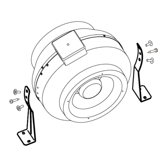
- Page 6 STEP 2 - To install the fan, remove the bolts on both sides of the casing, install the mounting brackets and tighten the bolts, aligning the holes in the brackets with the holes in the casing. STEP 3 – Position the fan in your preferred installation location and mark the position of the holes on the fan where the screws will then be placed.
- Page 7 STEP 5 – Connect the air ducts of the corresponding diameter to the fan. STEP 6 – Connect the fan to single-phase power mains through the automatic circuit breaker integrated into the fixed power mains. Cut power supply off prior to wireworks. The contact gap on all poles must be at least 3 mm.
-
Page 8: Wiring Diagram
STEP 8 – Connect the power cord wires to the terminal block and assemble the fan in reverse order by following the wiring diagram. WIRING DIAGRAM TERMINAL DESIGNATION KEYS AT WIRING DIAGRAMS: L - phase (only for 220-240 V power mains) N - 0 (only for 220-240 V power mains) QF –... - Page 9 STEP 9 – Place the cover back on the integral terminal box and secure the cover using the screws. STEP 10 – Turn on mains power.
-
Page 10: Maintenance
MAINTENANCE The product surfaces must be regularly cleaned from dirt and dust. Cut off power supply prior to any maintenance operations. To clean the fan, remove the ducting on either side of the fan, the self-tapping screws and remove the fan cover. Use a soft cloth or compressed air to remove external dust. - Page 12 reeze ation Manual...
Need help?
Do you have a question about the VKM and is the answer not in the manual?
Questions and answers