Table of Contents

Related Manuals for Fanco CFFCHZ4WHW


Summary of Contents for Fanco CFFCHZ4WHW
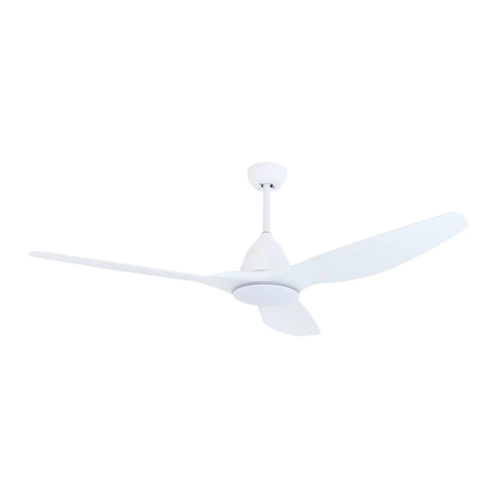
- Page 1 HORIZON DC 52” & 64” Ceiling Fan Installation Manual CFFCHZ4WHW - CFFCHZ4WHR - CFFCHZ4BRW - CFFCHZ4BRR CFFCHZ3WHW - CFFCHZ3WHR - CFFCHZ3BRW - CFFCHZ3BRR THIS IS NOT A DIY PRODUCT. THIS PRODUCT MUST BE INSTALLED BY A QUALIFIED ELECTRICIAN...
-
Page 2: Important Safeguards
YOUR FANCO HORIZON DC CEILING FAN - Congratulations on purchasing your new Fanco HORIZON DC Ceiling Fan. Before attempting to install your appliance it is important to read the instructions in this Installation Manual, even if you are a qualified installer already familiar with this type of product. -
Page 3: Fault Finder
FAULT FINDER: • Always check the “Trouble Shooting Checklist” included in this booklet before seeking warranty claim. • Mechanical noise may be noticed on installation. Allow at least 8 hours settling-in period. • Some fans may wobble more than others, even if identical. This does not necessarily indicate a fault. PREPARATION: 1. -
Page 4: Installation And Assembly
INSTALLATION AND ASSEMBLY CAUTION: Before installing the fan make sure you have turned OFF the electricity supply. SELECTING A LOCATION: 1. Choose a location for mounting the fan where the blades will have at least 2.1 metres of clearance from the floor. -
Page 5: Installation Steps
INSTALLATION STEPS 1. Install the blades on the motor housing 1.1. Unscrew screws from Motor (9 in total) 1.2. Align the blade with the screw holes on the motor housing & secure with the screws removed in step 1.1 1.3. Tighten all the blade screws securely and evenly. 2. - Page 6 INSTALLATION STEPS 3. Install the Downrod 3.1. Select rod size (12.5cm, 25cm or longer rod if purchased) and open Downrod Screws Bag 3.2. Thread wiring through the rod and insert rod above motor housing. 3.3. Insert Cross Pin (gently wriggle and rotate until it glides through both holes) 3.4.
- Page 7 INSTALLATION STEPS 4. Hang the fan 4.1. Secure the hanger bracket to the ceiling joist or suitable piece of timber inserted between the ceiling joists. The Hanger bracket should be secured using the screws provided. 4.2. Note - Fan and hanger bracket must be earthed during installation. 4.3.
-
Page 8: Electrical Connections
Ensure the power is off when installing this fan. For your convenience, and to assist in easy installation & cleaning, your ceiling fan is connected with Fanco’s easy connect system. Simply connect the male and female couplings, and then ensure excess wiring is re- tained inside the upper canopy. -
Page 9: Reverse Function
REVERSE FUNCTION The “Summer / Winter” reverse function is included in the remote control or wall control to make the fan rotate in an anti-clockwise direction during summer. In winter, this can be reversed, so that the blades now move in a clockwise direction. CARE &... - Page 10 REMOTE CONTROL SETTING AND OPERATION FOR DC FANS NOTE: The Hand Held Remote Control System is equipped with a learning frequency function which has code combina- tions to prevent potential interference from other remote units. The frequency on your Receiver and Transmitter units have been preset at the factory.
- Page 11 FUNCTIONS OF REMOTE TRANSMITTER ON/OFF FAN ON/OFF LIGHT SPEED OF THE FAN (1 = LOW, 5 = HIGH) 4. REVERSE DIRECTION (SUMMER/WINTER) TIMER FOR FAN 6. LED INDICATOR LIGHT 12V BATTERY SHOULD BE USED IN THIS REMOTE CONTROL To operate CCT (Colour Changing Technology) function; Use Light On/Off button to turn light on. Turn light off and on again immediately to change CCT setting, until desired CCT setting is found.
- Page 12 DC WALL CONTROL SETTING AND OPERATION FOR DC FANS 2. Erase the transmitter codes stored in the Wall control memory The ceiling fan receiver may be holding multiple wall control/transmitter codes in its memory. Assuming the steps outlined above in (1) have been tried and correctly followed, there could still be a situation where Wall control B is con- trolling both Fan A and Fan B, while Wall control A only controls Fan A.
-
Page 13: Troubleshooting
*DO NOT make any adjustments by applying pressure up or down on blades TECHNICAL DATA MODEL NO. RATED VOLTAGE DC MOTOR POWER CURRENT LIGHT POWER DIMMABLE CLFCHZLED CFFCHZ4WHW 220-240v 0.28 A 12W (Light Kit) N / A CFFCHZ4WHR 220-240v 0.28 A 12W (Light Kit) -
Page 14: Warranty Details
• Ceiling Fan must be installed for in home warranty to apply – The Fanco Ceiling fan must have been installed by a qualified electrician and must remain installed for the in home warranty service to apply. If there is an issue with the wiring, the fan should be left installed without the wiring connected. -
Page 15: Warranty Claims
Fanco warranty claim assessors or Fanco service agents to be unsafe or impractical to access. In these cases Fanco will still supply a replacement of any faulty products. At Fanco’s discretion, if a service agent has not already attended the warranty claim, the client may be reimbursed a standard fee of $95.00 (inc. - Page 16 WWW.FANCO.COM.AU...
Need help?
Do you have a question about the CFFCHZ4WHW and is the answer not in the manual?
Questions and answers