Table of Contents
Advertisement
Quick Links
Instruction Manual
D104786X012
Fisher
FIELDVUE
™
Controller
Contents
. . . . . . . . . . . . . . . . . . . . . . . . . . . . . . . . .
. . . . . . . . . . . . . . . . . . . . . . . . . . . . .
. . . . . . . . . . . . . . . . . . . . . . . . . . . . . . . . .
. . . . . . . . . . . . . . . . . . . . . . . . . . . . . . .
. . . . . . . . . . . . . . . . . . . . . . . . . .
. . . . . . . . . . . . . . . . . . . . . . . . .
. . . . . . . . . . . . . . . . . . . . . . . . . . . . . . . . . . . . .
. . . . . . . . . . . . . . . . . . . . . . . . . . . .
. . . . . . . . . . . . . . . . . . . . . . . . . . . . . . . . .
. . . . . . . . . . . . . . . . . . . . . . . . . . .
. . . . . . . . . . . . . . . . . . . . . . . . . . . . . . . . .
. . . . . . . . . . . . . . . . . . . . . . . .
. . . . . . . . . . . . . . . . . . . . . . . . . . . . . .
. . . . . . . . . . . . . . . . . . . . . . . . . . .
. . . . . . . . . . . . . . . . . . . . . . . . . . .
. . . . . . . . . . . . . . . . . . . . . . . . .
. . . . . . . . . . . . . . . . . . . . . . . .
. . . . . . . . . . . . . . . . . . . . . . . . .
. . . . . . . . . . . . . . . . . . . . . . . .
. . . . . . . . . . . . . . . . . . . . . . . .
. . . . . . . . . . . . . . . . . . . . . . . . . . .
. . . . . . . . . . . . . . . . . . . . . . . . . . .
. . . . . . . . . . . . . . . . . . . . . . . . . . . . . . . . .
. . . . . . . . . . . . . . . . . . . . . . . . . . . . . . .
. . . . . . . . . . . . . . . . . . . . . . . . .
. . . . . . . . . . . . . . . . . . . . . . . . . . . . . . .
. . . . . . . . . . . . . . . . . . . . . . . . . . . . . . .
. . . . . . . . . . . . . . . . . . . . . . . . . . . . . . . . . . . .
. . . . . . . . . . . . . . . . . . . . . . . . . .
. . . . . . . . . . . . . . . . . . . . . . . .
. . . . . . . . . . . . . . . . . . . . . . . . . .
. . . . . . . . . . . . . . . . . . . . . . . . .
. . . . . . . . . . . . . . . . . . . . . . . . . . . .
www.Fisher.com
DPC2K Digital Process
™
. . . . . . . .
. . . . . . . . . . . . . . . . . . . . . . .
. . .
. . . . . . . . . . . . .
. . . . . . . . . . . . . . . .
. . . . . . . . . . . . . . . . . . . .
. . . . . . . . . . . . . . . . . . . . . . .
. . . . . . . . . . . . . . . .
. . . . . . . . . . . . . . . . . . . . . .
. . . . . . . . . . . . .
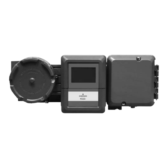
Figure 1. DPC2K Digital Process Controller
2
2
2
3
3
6
6
7
8
10
10
X1901
10
11
12
12
12
12
13
13
14
14
14
16
X1920
16
17
17
BASE UNIT WITH ANALOG OUTPUT
19
19
20
20
20
. . . . . . . . . . . . . . . . . . . . . . . . . . . . . . . . . . .
21
23
24
25
25
25
26
26
27
. . . . . . . . . . . . . . . . . . . . . . . . . . . . . . . . . . . .
27
28
29
DPC2K Digital Process Controller
BASE UNIT WITH
PNEUMATIC OUTPUT OPTION
. . . . . . . . . . . . . . . . . . . . . .
. . . . . . . . . . . . . . . . . . . . . . . . .
. . . . . . . . . . . . . . .
. . . . . . . . . . . . . . . . . . . . . .
. . . . . . . . . . . .
. . . . . . . . . . . . . . . . . . . . . . . . . . . . .
. . . . . . . . . . . . . . . . . . . . . . . . . . . . . . .
. . . . . . . . . . . . . . . . . . . . . . . .
. . . . . . . . . . . . . . . . . . . . .
. . . . . . . . . . . . . . . . . . . . . . . . . . .
. . . . . . . . . . . . . . . . . . . . . . . . . . . .
April 2024
30
30
30
32
33
36
41
41
43
. . . . . . . . .
44
46
47
47
50
Advertisement
Table of Contents
Troubleshooting

Related Manuals for Emerson Fisher FIELDVUE DPC2K


Summary of Contents for Emerson Fisher FIELDVUE DPC2K
-
Page 1: Table Of Contents
Instruction Manual DPC2K Digital Process Controller D104786X012 April 2024 Fisher FIELDVUE DPC2K Digital Process ™ ™ Controller Contents Figure 1. DPC2K Digital Process Controller Introduction ....... . . Installation, Pneumatic and Electrical Connections, and Initial Configuration . -
Page 2: Introduction
This manual also includes details for using the Local User Interface (LUI) to perform various operational tasks. Note This instruction manual may not be the latest version of the document. Click or scan the above QR code, contact your Emerson sales office, or visit our website at Fisher.com to access the latest version of D104786X012. -
Page 3: Description
D104786X012 April 2024 Description The Fisher FIELDVUE DPC2K digital process controller is an electro-pneumatic PID controller to meet your single continuous PID loop needs. Note Single feedback PID loop control is achieved using internal PID digital intelligence executing every 50 milliseconds. - Page 4 Instruction Manual DPC2K Digital Process Controller April 2024 D104786X012 Table 1. Specifications Base Unit (Analog Output) Communication Protocol Serial (RS-485): Modbus RTU, Supports function These specifications also apply to the Pneumatic codes Output Option Baud: Configured 9600 to 256,000 baud The Base Unit may also include the Process Pressure Default 115,200 Sensor Option...
- Page 5 Instruction Manual DPC2K Digital Process Controller D104786X012 April 2024 Table 1. Specifications (continued) Pneumatic Output Option Minimum Span: 0.4 bar / 6 psig Maximum Span: 9.5 bar / 140 psig The Base Unit specifications also apply to the Action: Single Pneumatic Output Option (7)(8)(9) Low Bleed Steady‐State Air Consumption...
-
Page 6: Related Documents
This section lists other documents containing information related to the DPC2K digital valve controller. These documents include: D Bulletin 34.7:DPC2K - Fisher FIELDVUE DPC2K Digital Process Controller (D104561X012) D Fisher FIELDVUE DPC2K Digital Process Controller Quick Start Guide (D104559X012) D Fisher LoopConnect Software Quick Start Guide (D104558X012) D Fisher FIELDVUE DPC2K Instruction Manual - latest version (D104786X012) -
Page 7: Security
Instruction Manual DPC2K Digital Process Controller D104786X012 April 2024 Security NOTICE Physical security is an important part of any security program and is fundamental to protecting your system. Unauthorized personnel may potentially cause significant damage to and/or misconfiguration of end users’ equipment. This could be intentional or unintentional and must be protected against by restricting access of unauthorized personnel in your facility. -
Page 8: Prestartup Checks
- Apply security patches and updates as they are released. Note Work with your Emerson sales office to stay informed and obtain access to security patches and updates. D Report security incidents and potential product vulnerabilities at: https://go.emersonautomation.com/reportvulnerability_en D Product Disposal Guidelines... - Page 9 Instruction Manual DPC2K Digital Process Controller D104786X012 April 2024 3. While in MANUAL mode – change output to 100% and 0%. Note Output pressure should match the bench set values of the actuator's (operating range) and not exceed the operating range of the actuator.
-
Page 10: Tuning Tips
Instruction Manual DPC2K Digital Process Controller April 2024 D104786X012 Tuning Tips Note When performing tuning procedures, keep in mind that the initial settings are guidelines. They will vary depending on the actual process being controlled. Output Response The response of the controlled parameter to a set point or load disturbance change may be classified in the following manner: D Over-damped response –... -
Page 11: Setup & Configuration
Instruction Manual DPC2K Digital Process Controller D104786X012 April 2024 Setup & Configuration Fisher LoopConnect software is used to configure and monitor the DPC2K. The software communicates with the DPC2K, allowing you to perform setup, commissioning, operating, and troubleshooting tasks. Figure 2. Local User Interface NAVIGATION BUTTONS ACTION BUTTONS... -
Page 12: Configuration Guidance
Instruction Manual DPC2K Digital Process Controller April 2024 D104786X012 Configuration Guidance LoopConnect software is required to configure the DPC2K digital valve controller. The software features five dashboards: Control (main dashboard), Events, Loop, I/O, and Instrument. The Control and Event dashboards are used for operation. The Loop, I/O, and Instrument dashboards are used for configuration. The software provides visual assists used to update status, provide configuration guidance, and highlight alert messages. -
Page 13: Device Status
Instruction Manual DPC2K Digital Process Controller D104786X012 April 2024 Figure 3. Example of how Colors and Notices Provide Configuration Guidance NOW VIEWING PANEL DEVICE STATUS PANEL EXPORT allows you to save a configuration file as a text file. Configuration Notices are visible on the Now Viewing panel when there are possible configuration errors or potential conflicts while configuring. -
Page 14: Setting Alerts
Instruction Manual DPC2K Digital Process Controller April 2024 D104786X012 Setting Alerts See Table 3 for DPC2K alerts and recommended actions. Expand DEVICE STATUS (example screen shown in Figure 4) by clicking on the icon to the right of the wording to show the card for setting these alerts. - Page 15 Instruction Manual DPC2K Digital Process Controller D104786X012 April 2024 Table 3. Available Alerts Instrument Alert Name Description Recommended Action RTC Time Lost Real time clock may not be accurate Check time and adjust as necessary. Device Variable Limit Alarm Value is outside alarm setting Check value and make appropriate changes.
-
Page 16: Process Alarms
Instruction Manual DPC2K Digital Process Controller April 2024 D104786X012 Process Alarms Process Alarms are configured on the LOOP and I/O dashboards for the associated measurement or control point. While alerts are associated with the instrument, alarms are defined based upon operating parameters. When an alarm is active, the Point Name and alarm type are displayed. -
Page 17: Instrument Dashboard
Instruction Manual DPC2K Digital Process Controller D104786X012 April 2024 Instrument Dashboard Note Configuration tasks generally start with the Instrument dashboard on the right and move left to the Loop dashboard. Security Settings DPC2K security methods consist of hardware and firmware configuration limitations. The Security Settings tab allows you to set software configuration limits. - Page 18 Instruction Manual DPC2K Digital Process Controller April 2024 D104786X012 Figure 6. Write Protection WRITE PROTECT SWITCH LUI TEMPORARY UNLOCK TIMER Firmware can allow or deny many of the writable parameters used for control to be read/write or just read only. The deny state is to not allow the writing of the list of operational parameters.
-
Page 19: Communication Settings
Instruction Manual DPC2K Digital Process Controller D104786X012 April 2024 Communication Settings The Communication Settings tab includes configuration information and allows for connecting to the instrument. Figure 7. Communication Settings LAN Settings The LAN Settings card allows you to configure the Ethernet port for compatibility of access with your own network or peer to peer connection. -
Page 20: Hart
Instruction Manual DPC2K Digital Process Controller April 2024 D104786X012 HART The HART card allows you to configures the POLLING ADDRESS for FSK and the ports for TCP and UDP connections The valid range of the polling address is 0-255, with 0 normally reserved for adding a new device on an FSK multidrop system. -
Page 21: Factory Information
Instruction Manual DPC2K Digital Process Controller D104786X012 April 2024 The VALID COMMANDS value is an assist for troubleshooting the connections when the INVALID COMMAND counter has been incrementing. Note INVALID COMMANDS and messages from the Host could indicate an out of date revision, firmware incompatibility, or some manner of software mismatch. - Page 22 Instruction Manual DPC2K Digital Process Controller April 2024 D104786X012 Figure 9. Instrument Dashboard, Factory Information, Pneumatic Module Installed CPU includes firmware and hardware information and allows you to update the firmware. LCD lets you configure the number of decimals places for the Local User Interface. PRESSURE SENSOR is visible when an integral Process Pressure Sensor (PPS) is installed.
-
Page 23: Device Data
Instruction Manual DPC2K Digital Process Controller D104786X012 April 2024 Device Data The Device Data tab, shown in Figure 10, includes internal measurements and time. Figure 10. Instrument Dashboard, Device Data Low Voltage Cutoff shows the value that sets the Low Voltage Cutoff Alert. The Low Voltage Cutoff Alert (when enabled) is active when the voltage is below the set value;... -
Page 24: Restart Or Restore Options
Instruction Manual DPC2K Digital Process Controller April 2024 D104786X012 To calibrate the supply: WARNING During calibration the valve will move full stroke. To avoid personal injury and property damage caused by the release of pressure or process fluid, isolate the valve from the process and equalize pressure on both sides of the valve or bleed off the process fluid. -
Page 25: I/O Dashboard
Instruction Manual DPC2K Digital Process Controller D104786X012 April 2024 I/O Dashboard The I/O dashboard is used to configure the Inputs and Outputs that are used in the PID control loop, including a remote setpoint, additional measurement, or a possible manual control output. Figure 11. -
Page 26: Input Calibrations
Instruction Manual DPC2K Digital Process Controller April 2024 D104786X012 Once the LOWER and UPPER RANGE values are entered, the LIVE VALUE will display the engineering units value of the measurement point. Below the engineering units value, the raw units are provided in mA for the 4-20 mA analog input. Note This value can be measured at the terminals by inserting a current meter. -
Page 27: Device Alerts
Instruction Manual DPC2K Digital Process Controller D104786X012 April 2024 Devices Expand DEVICE STATUS, located at the top of the right-hand navigation column, to enable and categorize alerts. The alert triggers for analog inputs are based upon the NE43 alert and default to common values used for 4-20 mA devices. Alerts The DPC2K allows these defaults to be modified in order to provide greater compatibility with existing systems. -
Page 28: Process Pressure Calibration
Instruction Manual DPC2K Digital Process Controller April 2024 D104786X012 Figure 13. Process Pressure Process Pressure Calibration The process pressure sensor is a sealed gauge sensor; it is factory calibrated to have a base reference of 1 Atmosphere (14.73 psi). Calibration may be required depending upon your process requirements/specifications, variations in altitude, measurement range, or weather conditions. -
Page 29: Travel Input
Instruction Manual DPC2K Digital Process Controller D104786X012 April 2024 3. Connect a pressure source and ensure it is delivering the proper pressure to the controller. Verify minimum and maximum readings. 4. Do not exceed the normal operating pressure range of the process pressure sensor. LoopConnect Software: The calibration information shown is the date of the last calibration. -
Page 30: Travel Calibration
Instruction Manual DPC2K Digital Process Controller April 2024 D104786X012 Travel Calibration Travel Calibration is used to apply the end stops from non-contact magnetic array position. 1. Move the measured device from a zero position and use the 0% Calibration button. 2. - Page 31 Instruction Manual DPC2K Digital Process Controller D104786X012 April 2024 The ACTION field is a manually added note to the operator that can be used to describe the output control action. Including this information provides a better understanding of how the output responds to control signals. The description for air-operated valves may be: increase output to open or increase output to decrease flow.
-
Page 32: Analog Output Calibration
Instruction Manual DPC2K Digital Process Controller April 2024 D104786X012 Analog Output Calibration The Analog Output is calibrated at the factory and should not need to be re-calibrated; however if adjustment is required perform the calibration procedure. WARNING During calibration the valve will move full stroke. To avoid personal injury and property damage caused by the release of pressure or process fluid, isolate the valve from the process and equalize pressure on both sides of the valve or bleed off the process fluid. -
Page 33: Pneumatic Output
Instruction Manual DPC2K Digital Process Controller D104786X012 April 2024 Fault State Conditions The following conditions can trigger the configured Fault State: D AO Status Poor: Firmware can sporadically communicate with the AO, or the AO is occasionally returning invalid information. D AO Status Bad: Firmware can no longer control the AO, or the AO is returning invalid information. D AO Stale: Reserved for future use. - Page 34 Instruction Manual DPC2K Digital Process Controller April 2024 D104786X012 When the pneumatic output module is installed in a DPC2K, the configuration screen is as shown in Figure 16. Expand the pneumatic output card to enter a more descriptive name up to 16 characters in the POINT NAME field. Once AUTO CAL is run on the Pneumatic Output the ACTION (either Increase to Open or Increase to Close) will be determined and shown.
- Page 35 Instruction Manual DPC2K Digital Process Controller D104786X012 April 2024 While the OUTPUT VALUE shows the current value, the READBACK value shows the actual travel value. The READBACK SOURCE is a dropdown which allows you to select the integral travel input when the DPC2K is mounted to an actuator or remote travel for cases where the instrument is pole mounted.
-
Page 36: Pneumatic Output Calibration
Instruction Manual DPC2K Digital Process Controller April 2024 D104786X012 Pneumatic Output Calibration LoopConnect Software Auto Cal WARNING During calibration the valve will move full stroke. To avoid personal injury and property damage caused by the release of pressure or process fluid, isolate the valve from the process and equalize pressure on both sides of the valve or bleed off the process fluid. - Page 37 Instruction Manual DPC2K Digital Process Controller D104786X012 April 2024 Figure 18. Calibration Options 2. Calibration Options (see Figure 18) a. Select Calibrate Supply to calibrate the Supply Pressure Sensor. Notes The Calibrate Supply procedure requires a calibrated gauge or source be placed upon the supply inlet to the pneumatic module. This option allows calibration of the supply pressure by following the prompts and entering the known value applied.
- Page 38 Instruction Manual DPC2K Digital Process Controller April 2024 D104786X012 Then APPLY & CONTINUE. Note If Calibrate Supply or Calibrate Output A were not selected in Step 2, Supply Pressure will be skipped. 4. Actuator This step requires an understanding of the valve position. Closed = 0.0%, Open = 100%. This information is shown on the VENT/ SUPPLY readback value to the left of this screen.
- Page 39 Instruction Manual DPC2K Digital Process Controller D104786X012 April 2024 Fault State A Fault State defines the behavior of the output when a trigger condition is Active. A DPC2K has three configuration options which control the behavior of the output when one of the trigger conditions exist. 1.
- Page 40 Instruction Manual DPC2K Digital Process Controller April 2024 D104786X012 Advanced Advanced is an informational read-only screen, shown in Figure 19, to assist troubleshooting the pneumatic output. You access this by clicking the checkbox in the upper right corner of the Pneumatic Output card. Figure 19.
-
Page 41: Loop Dashboard
Instruction Manual DPC2K Digital Process Controller D104786X012 April 2024 Loop Dashboard The Loop dashboard provides configuration for the controller. It features a drag and drop interface to configure the I/O to the correct parameters of the process loop. The top row of the dashboard provides information about the process loop. The DESCRIPTOR field can be updated with the loop name. - Page 42 Instruction Manual DPC2K Digital Process Controller April 2024 D104786X012 Expand the SP card to configure Alarms to provide notification of potential setpoint warnings. Once an alarm is active, it will remain on until it passes outside the deadband. Figure 21. SP Card Fault State A Fault State defines the behavior of the setpoint when a trigger condition is Active.
-
Page 43: Pv (Process Variable)
Instruction Manual DPC2K Digital Process Controller D104786X012 April 2024 Fault State Conditions The following conditions trigger the configured Fault State: D SP Status Poor: Firmware can sporadically communicate with the SP, or the SP is occasionally returning invalid information. D SP Status Bad: Firmware can no longer read the SP, or the SP is returning invalid information. D SP Status Stale (reserved for future use) PV (Process Variable) The Process Variable source may be configured from Input cards at the bottom of the dashboard by dragging the... -
Page 44: Pid (Proportional, Derivative, Integral)
Instruction Manual DPC2K Digital Process Controller April 2024 D104786X012 Once expanded, alarms can be set for the Process Variable. Only values within the process range are valid for Process alarms. Once an alarm is active it will remain on until it passes outside the deadband. PID (Proportional, Integral, Derivative) ACTION SELECTION is a user entered reminder of what will happen with manual entries for the Output. - Page 45 Instruction Manual DPC2K Digital Process Controller D104786X012 April 2024 3. Hold Last Value will maintain the output in the last used value while any of the triggers are active. Enter a shed time for the fault to clear and update to the latest value. If the Fault State is configured to Manual, the active trigger must clear, and you must acknowledge the fault before the output is updated to the latest value.
-
Page 46: Output
Instruction Manual DPC2K Digital Process Controller April 2024 D104786X012 Output The output can be configured to two potential outputs: D The integral analog output which is a 4-20 mA current loop. D The Pneumatic Module which provides a modulated air output in the range of 0-100% of the operating range for air operated actuators. -
Page 47: Operation And Monitoring
Instruction Manual DPC2K Digital Process Controller D104786X012 April 2024 Operation and Monitoring Control Dashboard The Control dashboard is the main operations dashboard for the process loop. From this view, you can quickly discern how the loop is performing to the setpoint, the process variable itself, and the condition of the final control element. Figure 25. - Page 48 Instruction Manual DPC2K Digital Process Controller April 2024 D104786X012 When SP is in REMOTE, the connector from the configured input will show up as a solid connector. When in LOCAL, the indicator is a dashed line. PV (Process Variable) is the measurement which is being controlled. The PV should track the SP closely. The controller’s PID algorithm drives the output signal to minimize the error between PV and SP.
- Page 49 Instruction Manual DPC2K Digital Process Controller D104786X012 April 2024 PID Tuning PROPORTIONAL GAIN is the gain applied to error to drive output. INTEGRAL is the integration applied to drive output. DERIVATIVE is the gain applied delta PV to drive output. The PID ERROR DEADBAND sets boundaries during which the PID output does not change.
-
Page 50: Events Dashboard
Instruction Manual DPC2K Digital Process Controller April 2024 D104786X012 Events Dashboard The DPC2K retains an event log in the internal memory. To view these events, open the Events dashboard. The list of events appear in chronological order with the latest at the top of the list. The internal log is updated every minute. LoopConnect allows you to select from predefined historical datasets, as the log may become large after years of operation. -
Page 51: Maintenance And Troubleshooting
Instruction Manual DPC2K Digital Process Controller D104786X012 April 2024 Maintenance and Troubleshooting The DPC2K digital process controller enclosure is rated Type 4X and IP66, therefore periodic cleaning of internal components is not required. If the DPC2K is installed in an area where the exterior surfaces tend to get heavily coated or layered with industrial or atmospheric contaminants, it is recommended that the vent be periodically removed and inspected to ensure there is no partial or full obstruction. -
Page 52: Removing The Magnet Assembly
Instruction Manual DPC2K Digital Process Controller April 2024 D104786X012 the product specifications, as indicated in Table 1, and may also impair operations and the intended function of the device and could cause personal injury and property damage. Select the appropriate maintenance procedure and perform the numbered steps. Each procedure requires that the supply pressure be shut off before beginning maintenance. - Page 53 Instruction Manual DPC2K Digital Process Controller D104786X012 April 2024 Replacing the I/P Filter A screen in the supply port beneath the I/P converter serves as a secondary filter for the supply medium. To replace this filter, perform the following procedure: 1.
- Page 54 Instruction Manual DPC2K Digital Process Controller April 2024 D104786X012 Replacing the I/P Converter 1. Inspect the condition of the O‐ring and screen in the module base (see Figure 28). Replace them, if necessary. Apply silicone lubricant to the O‐rings. 2. Apply silicone lubricant to the two boots shown in Figure 29, and ensure they are properly installed on the electrical leads.
-
Page 55: Pneumatic Relay
Instruction Manual DPC2K Digital Process Controller D104786X012 April 2024 Pneumatic Relay Refer to Figure 30 and 34 for key number locations. The pneumatic relay is located on the front of the module base. Note This procedure is only applicable to the DPC2K with Pneumatic Output option. After relay submodule replacement, calibrate the digital process controller to maintain accuracy specifications. -
Page 56: Process Pressure Sensor Assembly
Instruction Manual DPC2K Digital Process Controller April 2024 D104786X012 Process Pressure Sensor (PPS) Assembly Refer to Figure 32 and 34. Removing the PPS Assembly 1. Using a 3/16 mm hex socket wrench, remove the four socket head cap screws to remove the PPS cover. 2. - Page 57 Instruction Manual DPC2K Digital Process Controller D104786X012 April 2024 Replacing the PPS Assembly Note This procedure can be used to replace the PPS assembly or for first time installation of a PPS assembly. When replacing the PPS assembly, ensure that the pressure range of the new sensor is the same as the one removed. For a first time installation, you will need to remove the existing process pressure sensor cover and punch out the knockout on the right front of it.
-
Page 58: Vent
Instruction Manual DPC2K Digital Process Controller April 2024 D104786X012 Vent The vent is located on the bottom right of the instrument (see Figure 34). Note This procedure is only applicable to the DPC2K with Pneumatic Output option. Cleaning the Vent (Figure 33) 1. -
Page 59: Troubleshooting
Instruction Manual DPC2K Digital Process Controller D104786X012 April 2024 5. Allow the components to dry before reinstalling. 6. Reassemble the vent by inserting the filter and umbrella valve between the two vent housing components as shown in Figure 33. 7. Insert the O-ring into the Pneumatic Module Housing Assembly. 8. - Page 60 Instruction Manual DPC2K Digital Process Controller April 2024 D104786X012 Table 4. Troubleshooting Chart Fault Possible Cause Check Correction 1 Process wanders or cycles about 1.1 Proportional, Integral, 1.1 Refer to the startup procedures 1.1 If stable control cannot be set point Derivative, or Deadband settings for controller settings attained, and all other elements of the loop are functionally correct,...
- Page 61 Instruction Manual DPC2K Digital Process Controller D104786X012 April 2024 Table 4. Troubleshooting Chart (continued) Fault Possible Cause Check Correction 4 Controller remains at zero output 4.1 Verify pneumatic output type 4.1 Monitor the output pressure 4.1 Replace pneumatic output as with external gauge, place output necessary in MANUAL and check 0 and 100% output pressure...
-
Page 62: Parts Ordering
Use only genuine Fisher replacement parts. Components that are not supplied by Emerson, should not, under any circumstances, be used in any Fisher instrument. Use of components not supplied by Emerson may void your warranty, might adversely affect the performance of the instrument, and could cause personal injury or property damage. - Page 63 Instruction Manual DPC2K Digital Process Controller D104786X012 April 2024 Figure 34. DPCP2K Assembly Drawings COVER OPEN RIGHT VIEW TO SHOW LUI PUSHBUTTONS FRONT VIEW BASE UNIT SCREWS (2) WITH ANALOG OUTPUT COVER TERMINAL BOX CAP RIGHT VIEW FRONT VIEW BASE UNIT WITH PNEUMATIC OUTPUT OPTION TERMINAL BOX CAP REMOVED...
- Page 64 Instruction Manual DPC2K Digital Process Controller April 2024 D104786X012 Figure 34. DPCP2K Assembly Drawings (continued) SCREWS FOR INSTALLING RELAY ASSEMBLY (4) RELAY ASSEMBLY FEEDTHROUGH SHROUD I/P CONVERTER (SEE FIGURE 28 AND 29) SOCKET-HEAD SCREWS FOR INSTALLING I/P CONVERTER (4) MODULE BASE VENT VIEW A-A PNEUMATIC...
- Page 65 Instruction Manual DPC2K Digital Process Controller D104786X012 April 2024 Figure 35. Pipestand Mounting Kit U-BOLT STRAP HEX NUT PIPESTAND MOUNT PLATE THREADED U-BOLT SOCKET HEAD CAP SCREW...
- Page 66 Instruction Manual DPC2K Digital Process Controller April 2024 D104786X012 Appendix A Local User Interface (LUI) Flow Chart Operate OPERATE SETPOINT MAIN MENU SETPOINT SOURCE PID Setpoint Source: Operate HOME Local PID Output Lock: Input\Output Remote SCREEN Tuning Setup Instrument LOCK/UNLOCK MESSAGE SETPOINT Lock...
- Page 67 Instruction Manual DPC2K Digital Process Controller D104786X012 April 2024 Input/Output Inputs INPUTS AI 1 MAIN MENU INPUT/OUTPUT Analog Input 1 AI-1: Operate Inputs Analog Input 2 Input\Output Outputs Process Pressure Status: Setup Device Range: Instrument Calibrate Line Temp INPUTS AI-2: INPUT/OUTPUT Analog Input 1 Inputs...
- Page 68 Instruction Manual DPC2K Digital Process Controller April 2024 D104786X012 Outputs (continued) MODE PNEUMATIC OUTPUT PNEUMATIC OUTPUT OUTPUTS Mode: Manual Lock: Pneumatics Analog Output Auto Output: not in use Pneumatic Output ReadBk: PNEUMATIC OUTPUT LOCK/UNLOCK MESSAGE Mode: Lock: Lock You must first set the Output: Unlock Mode to Manual...
- Page 69 Instruction Manual DPC2K Digital Process Controller D104786X012 April 2024 Setup MAIN MENU SETUP WRITE PROTECT Operate Write Protect Lock Status Input\Output LUI Temporary Communication Setup Settings Unlock Timer Instrument Reset COMM. SETTINGS SETUP DHCP DHCP: Write Protect Disabled Communication Enabled GTWY: Settings MASK:...
- Page 70 Instruction Manual DPC2K Digital Process Controller April 2024 D104786X012 Appendix B DPC2K Modbus Register Information Coil Modbus Priority Description Type Size Read/Write Address Address − PID_PV.Value Float − PID_SP.Value Float − PID_OUT.Value Float − PID_MV.Value Float − AI_1_ENG_VALUE.Value Float − AO_CURRENT_ENG_VALUE.Value Float −...
- Page 71 Instruction Manual DPC2K Digital Process Controller D104786X012 April 2024 Coil Modbus Priority Description Type Size Read/Write Address Address − INPUT_VOLTAGE.High Boolean − INPUT_VOLTAGE.Low Boolean − ELECTRONIC_TEMPERATURE.High Boolean − ELECTRONIC_TEMPERATURE.Low Boolean − AI_1_ENG_VALUE.Override Boolean − AI_1_ENG_VALUE.Manual Boolean − AO_CURRENT.Override Boolean − AO_CURRENT.Manual Boolean −...
- Page 72 Fisher, FIELDVUE, and LoopConnect are marks owned by one of the companies in the Emerson business unit of Emerson Electric Co. Emerson and the Emerson logo are trademarks and service marks of Emerson Electric Co.
Need help?
Do you have a question about the Fisher FIELDVUE DPC2K and is the answer not in the manual?
Questions and answers