Emerson FISHER FIELDVUE DLC3010 Instruction Manual
Digital level controller
Hide thumbs
Also See for FISHER FIELDVUE DLC3010:
- Quick start manual (42 pages) ,
- Instruction manual (2 pages)
Table of Contents
Advertisement
Instruction Manual
D102748X012
Fisher
FIELDVUE
™
Controller
This manual applies to:
Device Type
Device Revision
Contents
Section 1 Introduction and Specifications
. . . . . . . . . . . . . . . . . . . . . . . . . . . . . .
. . . . . . . . . . . . . . . . . . . . . . . . . . . . . . . . . .
. . . . . . . . . . . . . . . . . . . . . . . . . . . . . . . .
. . . . . . . . . . . . . . . . . . . . . . . . . . .
. . . . . . . . . . . . . . . . . . . . . . . . . . .
. . . . . . . . . . . . . . . . . . . . . . . . . . . . . . . . . . .
. . . . . . . . . . . . . . . . . . . . . . . . . .
. . . . . . . . . . . . . . . . . . . . . . . .
. . . . . . . . . . . . . . . . . . . . . . . . . . . . . .
. . . . . . . . . . . . . . . . . . . . . . . . . . . . . . . .
. . . . . . . . . . . . . . . . . . . . . . . . . . . . . . . . .
. . . . . . . . . . . . . . . . . . . . . . . . . .
. . . . . . . . . . . . . . . . . . . . . . . . . . .
. . . . . . . . . . . . . . . . . . . . . . . . . . .
www.Fisher.com
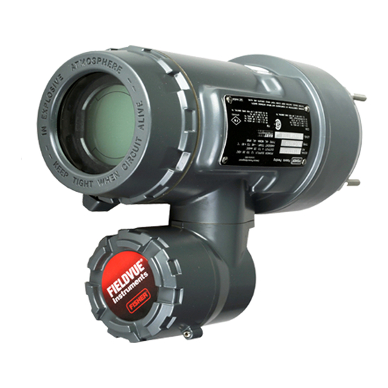
DLC3010 Digital Level
™
DLC3010
1
1
8
4
. . . . . . . . . . . . . . . .
. . . . . . . . . . . . . . . . .
. . . . . .
. . . . . . . . . . .
. . . . . . . . . . . . . . . . . . . .
. . . . . . . . . . . . . . . . . . . .
. . . . . . . . . . . .
. . . . . . . . . . . . . . . . .
. . . . . . . . . . . . .
. . . . . . . . . . . . . . .
. . . . . . . . . . . . .
. . . . . . . . . . . . . . . . .
. . . . . . . . . . . . . . . . . . . .
.
3
3
3
3
W7977-2
4
5
5
15
15
15
17
. . . . . . . . . . . . . . . . . . . . . . . . . . . . . . . . . . .
17
17
18
20
20
22
22
23
24
24
25
25
25
. . . . . . . . . . . . . . . . . . . . . . . . . . . . . . . . . . . .
25
25
. . . . . . . . . . . . . . . . . . . . . . . . . . . . . . . . . . .
26
26
DLC3010 Digital Level Controller
. . . . . . . . . . . . . . . . . . . . . . . . . . . . . . .
. . . . . . . . . . . . . . . . . . . .
. . . . . . . . . . . . . . . . . . . . . . . . . . . . .
. . . . . . . . . . . . . . . . . . . .
. . . . . . . . . . . . . . . . . . .
. . . . . . . . . . . . . . . . . . . . . . . . . . . . . . . . .
. . . . . . . . . . . . . . . . . . . . . . . . .
. . . . . . . . . . . . . . . . . . . .
. . . . . . . . . . . . . . . . . . . . . . . . . . . . . .
. . . . . . . . . . . . . . . . . . . . . . . . . . . . . . .
. . . . . . . . . . . . . . . . . . . . . . . . . . . . . . . . . .
. . . . . . . . . . . . . . . . . . . . . . . . . . . . . . .
. . . . . . . . . . . . . . . . . . . . . . . . . . . . . . . . . .
. . . . . . . . . . . . . . . . . . . . . . . . . .
. . . . . . . . . . . . . . . . . . . . . . . .
May 2018
27
28
28
29
99
31
. . . . . . . .
35
35
36
36
36
36
39
40
40
42
43
44
48
Advertisement
Table of Contents

Related Manuals for Emerson FISHER FIELDVUE DLC3010


Summary of Contents for Emerson FISHER FIELDVUE DLC3010
-
Page 1: Table Of Contents
Instruction Manual DLC3010 Digital Level Controller D102748X012 May 2018 Fisher FIELDVUE DLC3010 Digital Level ™ ™ Controller This manual applies to: DLC3010 Device Type Device Revision Hardware Revision Firmware Revision DD Revision Contents Section 1 Introduction and Specifications Scope of Manual . - Page 2 Instruction Manual DLC3010 Digital Level Controller May 2018 D102748X012 Communications ......Section 6 Maintenance and Polling Address .
-
Page 3: Scope Of Manual
If you have any questions about these instructions, contact your Emerson sales office or Local Business Partner. -
Page 4: Dd Revision
DLC3010 Digital Level Controller Introduction and Specifications Instruction Manual May 2018 D102748X012 displacer, which rotates the torque tube shaft. This rotary motion is applied to the digital level controller, transformed to an electrical signal and digitized. The digital signal is compensated and processed per user configuration requirements, and converted back to a 4‐20 mA analog electrical signal. -
Page 5: Related Documents
D Technical Monograph 7: The Dynamics of Level and Pressure Control D Technical Monograph 18: Level‐Trol Density Transmitter D Technical Monograph 26: Guidelines for Selection of Liquid Level Control Equipment () These documents are available from your Emerson sales office or Local Business Partner. Also visit our website at www.Fisher.com. Educational Services... - Page 6 DLC3010 Digital Level Controller Introduction and Specifications Instruction Manual May 2018 D102748X012 Table 1‐1. DLC3010 Digital Level Controller Specifications Available Configurations Performance w/ NPS 3 DLC3010 Digital Level Controller: DLC3010 Performance 249W, Using w/ All Other Mounts on caged and cageless 249 sensors. See Digital Level Criteria a 14‐inch...
- Page 7 TIIS— Technology Institution of Industrial Safety User‐configurable alarms: Hi and Lo limit process (Japan) alarms, Hi and Lo limit process temperature alarms, Contact your Emerson sales office or Local Business and Hi and Lo limit electronics temperature alarms Partner for classification/certification specific information...
-
Page 8: Firmware Revision
NOTE: Specialized instrument terms are defined in ANSI/ISA Standard 51.1 - Process Instrument Terminology. 1. LCD meter may not be readable below -20_C (-4_F) 2. Contact your Emerson sales office or application engineer if temperatures exceeding these limits are required. Table 1‐2. EMC Summary Results—Immunity... - Page 9 DLC3010 Digital Level Controller Instruction Manual Introduction and Specifications May 2018 D102748X012 Figure 1‐2. Theoretical Reversible Temperature Effect on Common Torque Tube Materials, Degrees Celsius TORQUE RATE REDUCTION (NORMALIZED MODULUS OF RIGIDITY) 1.00 0.98 0.96 0.94 0.92 N05500 N06600 0.90 N10276 0.88 0.86...
- Page 10 DLC3010 Digital Level Controller Introduction and Specifications Instruction Manual May 2018 D102748X012 Figure 1‐3. Theoretical Reversible Temperature Effect on Common Torque Tube Materials, Degrees Fahrenheit TORQUE RATE REDUCTION (NORMALIZED MODULUS OF RIGIDITY) 1.00 0.98 0.96 0.94 0.92 N05500 N06600 0.90 N10276 0.88 0.86...
- Page 11 316 Stainless Steel, Laminate/SST Torque Tube N05500 Gaskets N06600, N10276 N04400/PTFE 1. N05500 is not recommended for spring applications above 232_C -73_C (-100_F) 204_C (400_F) (450_F). Contact your Emerson sales office or application engineer if Gaskets temperatures exceeding this limit are required.
- Page 12 DLC3010 Digital Level Controller Introduction and Specifications Instruction Manual May 2018 D102748X012 Table 1‐6. Caged Displacer Sensors STANDARD CAGE, HEAD, EQUALIZING CONNECTION TORQUE TUBE SENSOR PRESSURE RATING AND TORQUE TUBE ARM ORIENTATION Style Size (NPS) MATERIAL Screwed 1‐1/2 or 2 Cast iron CL125 or CL250 Flanged...
- Page 13 DLC3010 Digital Level Controller Instruction Manual Introduction and Specifications May 2018 D102748X012 Figure 1‐4. Style Number of Equalizing Connections STYLE 3 STYLE 1 UPPER AND LOWER SIDE CONNECTIONS, TOP AND BOTTOM CONNECTIONS, SCREWED (S-3) OR FLANGED (F-3) SCREWED (S-1) OR FLANGED (F-1) STYLE 4 STYLE 2 UPPER SIDE AND BOTTOM CONNECTIONS,...
- Page 14 DLC3010 Digital Level Controller Introduction and Specifications Instruction Manual May 2018 D102748X012...
-
Page 15: Section 2 Installation
DLC3010 Digital Level Controller Instruction Manual Installation D102748X012 May 2018 Section 2 Installation2-2- This section contains digital level controller installation information including an installation flowchart (figure 2‐1), mounting and electrical installation information, and a discussion of failure mode jumpers. Configuration: On the Bench or in the Loop Configure the digital level controller before or after installation. - Page 16 DLC3010 Digital Level Controller Installation Instruction Manual May 2018 D102748X012 Figure 2‐1. Installation Flowchart START HERE Check Alarm Jumper Position Wire Factory mounted Digital Level on 249 sensor? Controller Power Digital Level Controller High Install heat temperature insulator application? assembly Enter Tag, Messages, Date, and check or set Mount and Wire...
-
Page 17: Mounting
Refer to the DLC3010 Quick Start Guide (D103214X012) that ships with the instrument for Hazardous Area Classifications and Special Instructions for “Safe Use” and Installations in Hazardous Locations. If a copy of this quick start guide is needed contact your Emerson sales office or Local Business Partner, or visit our website at www.Fisher.com. -
Page 18: Digital Level Controller Orientation
DLC3010 Digital Level Controller Installation Instruction Manual May 2018 D102748X012 Figure 2‐2. Typical Caged Sensor Mounting Figure 2‐3. Typical Cageless Sensor Mounting Digital Level Controller Orientation Mount the digital level controller with the torque tube shaft clamp access hole (see figure 2‐4) pointing downward to allow accumulated moisture drainage. - Page 19 DLC3010 Digital Level Controller Instruction Manual Installation D102748X012 May 2018 Note If alternate drainage is provided by the user, and a small performance loss is acceptable, the instrument could be mounted in 90 degree rotational increments around the pilot shaft axis. The LCD meter may be rotated in 90 degree increments to accommodate this.
-
Page 20: Mounting The Digital Level Controller On A 249 Sensor
DLC3010 Digital Level Controller Installation Instruction Manual May 2018 D102748X012 Mounting the Digital Level Controller on a 249 Sensor Refer to figure 2‐4 unless otherwise indicated. 1. If the set‐screw in the access handle (figure 2‐6) is driven against the spring plate, back it out until the head is flush with the outer surface of the handle, using a 2 mm hex key. - Page 21 DLC3010 Digital Level Controller Instruction Manual Installation D102748X012 May 2018 Figure 2‐7. Guidelines for Use of Optional Heat Insulator Assembly AMBIENT TEMPERATURE (_C) HEAT INSULATOR REQUIRED NO HEAT INSULATOR NECESSARY -100 HEAT INSULATOR -200 COLD REQUIRED -325 100 120 AMBIENT TEMPERATURE (_F) STANDARD TRANSMITTER NOTES: 1 ...
-
Page 22: Electrical Connections
DLC3010 Digital Level Controller Installation Instruction Manual May 2018 D102748X012 Electrical Connections WARNING Select wiring and/or cable glands that are rated for the environment of use (such as hazardous area, ingress protection and temperature). Failure to use properly rated wiring and/or cable glands can result in personal injury or property damage from fire or explosion. -
Page 23: Field Wiring
DLC3010 Digital Level Controller Instruction Manual Installation D102748X012 May 2018 determine the required lift‐off voltage. If you know your total loop resistance you can determine the lift‐off voltage. If you know the available supply voltage, you can determine the maximum allowable loop resistance. Figure 2‐10. -
Page 24: Grounding
DLC3010 Digital Level Controller Installation Instruction Manual May 2018 D102748X012 Figure 2‐11. Digital Level Controller Terminal Box 4‐20 mA LOOP TEST CONNECTIONS 1/2 NPT CONNECTIONS CONDUIT CONNECTION CONNECTIONS EXTERNAL INTERNAL GROUND GROUND CONNECTION CONNECTION 1/2 NPT CONDUIT FRONT VIEW REAR VIEW CONNECTION W8041 CAUTION... -
Page 25: Power/Current Loop Connections
DLC3010 Digital Level Controller Instruction Manual Installation D102748X012 May 2018 Power/Current Loop Connections Use ordinary copper wire of sufficient size to ensure that the voltage across the digital level controller terminals does not go below 12.0 volts DC. Connect the current signal leads as shown in figure 2‐9. After making connections, recheck the polarity and correctness of connections, then turn the power on. -
Page 26: Test Connections
DLC3010 Digital Level Controller Installation Instruction Manual May 2018 D102748X012 Test Connections WARNING Personal injury or property damage caused by fire or explosion may occur if the following procedure is attempted in an area which contains a potentially explosive atmosphere or has been classified as hazardous. Confirm that area classification and atmosphere conditions permit the safe removal of the terminal box cap before proceeding. -
Page 27: Alarm Jumper
DLC3010 Digital Level Controller Instruction Manual Installation D102748X012 May 2018 Figure 2‐12. Multichannel Installations Lead Instrument No. 1 DC Power Readout Supply Lead Device No. 1 Battery Backup Instrument Lead No. 2 Readout Lead Device No. 2 To Additional Between Instruments 230 and 600 W if no Load Resistor... -
Page 28: Changing Jumper Position
DLC3010 Digital Level Controller Installation Instruction Manual May 2018 D102748X012 Changing Jumper Position WARNING Personal injury or property damage caused by fire or explosion may occur if the following procedure is attempted in an area which contains a potentially explosive atmosphere or has been classified as hazardous. Confirm that area classification and atmosphere conditions permit the safe removal of the instrument cover before proceeding. -
Page 29: Installation In Conjunction With A Rosemount 333 Hart Tri-Loopt Hart-To-Analog Signal Converter
DLC3010 Digital Level Controller Instruction Manual Installation D102748X012 May 2018 Installation in Conjunction with a Rosemount 333 HART Tri‐Loop HART‐to‐Analog Signal Converter Use the DLC3010 digital level controller in operation with a Rosemount 333 HART Tri-Loop HART‐to‐Analog Signal Converter to acquire an independent 4‐20 mA analog output signal for the process variable, % range, electronics temperature, and process temperature. - Page 30 DLC3010 Digital Level Controller Installation Instruction Manual May 2018 D102748X012 Commissioning the Digital Level Controller for use with the HART Tri‐Loop To prepare the digital level controller for use with a 333 HART Tri‐Loop, you must configure the digital level controller to burst mode, and select the dynamic variables to burst.
-
Page 31: Section 3 Overview
DLC3010 Digital Level Controller Instruction Manual Overview May 2018 D102748X012 Section 3 Overview 3-3- Overview Field Communicator Overview (1) Device Status Good There are no active alerts and instrument is In Service. Failed The highest severity active alert is in the Failed category. Maintenance The highest severity active alert is in the Maintenance category. - Page 32 DLC3010 Digital Level Controller Overview Instruction Manual May 2018 D102748X012 Secondary See the Calibration section, starting on page 58, for Secondary calibration information. Ranging D Upper Sensor Limit indicates the maximum usable value for a Range Value. D Lower Sensor Limit indicates the minimum usable value for a Range Value. D Minimum Span is the difference between the Upper Range Value and the Lower Range Value below which amplification of instrument errors may become a concern.
- Page 33 DLC3010 Digital Level Controller Instruction Manual Overview May 2018 D102748X012 Device Information Identification Follow the prompts on the Field Communicator display to view the following information. D Tag (also called HART tag) is a unique name (up to eight characters) that identifies the physical instrument. D Distributor identifies the distributor of the instrument.
- Page 34 DLC3010 Digital Level Controller Overview Instruction Manual May 2018 D102748X012 Alarm Type and Security D Alarm Configuration Alarm Jumper indicates the analog output commanded in an alarm condition, either Fail Lo (3.7 mA) or Fail Hi (22.5 mA). Notes Consider the effect of an alarm annunciation on the process and set alarm jumper position accordingly. When Output Action is 'Direct': A Hi alarm setting will result in an alarm-state output consistent with a very high process.
-
Page 35: Section 4 Setup And Calibration
DLC3010 Digital Level Controller Instruction Manual Configuration D102748X012 May 2018 Section 4 Configuration and Calibration 4-4- Initial Setup If a DLC3010 digital level controller ships from the factory mounted on a 249 sensor, initial setup and calibration is not necessary. The factory enters the sensor data, couples the instrument to the sensor, and calibrates the instrument and sensor combination. -
Page 36: Configuration Advice
DLC3010 Digital Level Controller Instruction Manual Configuration D102748X012 May 2018 D Torque Tube Material Note A sensor with an N05500 torque tube may have NiCu on the nameplate as the torque tube material. D Instrument mounting (right or left of displacer) D Measurement Application (level, interface, or density) Configuration Advice Guided Setup directs you through initialization of configuration data needed for proper operation. - Page 37 Local Business Partner and provide the serial number of the sensor. 2. This table applies to sensors with vertical displacers only. For sensor types not listed, or sensors with horizontal displacers, contact your Emerson sales office or Local Business Partner for the driver rod length.
- Page 38 DLC3010 Digital Level Controller Instruction Manual Configuration D102748X012 May 2018 4. Select the measurement application (liquid level, interface level, or liquid density). Note For interface applications using standard hardware, if the 249 is not installed on a vessel, or if the cage can be isolated, calibrate the instrument with weights, water, or other standard test fluid, in level mode.
-
Page 39: Coupling
DLC3010 Digital Level Controller Instruction Manual Configuration D102748X012 May 2018 PV alert thresholds are initialized at 100%, 95%, 5% and 0% span. PV alert deadband is initialized to 0.5% span. PV alerts are all disabled. Temperature alerts are enabled. D If Liquid Density mode was chosen, setup is complete. D If Interface Level or Liquid Level mode was chosen, you are advised that process fluid data must be configured. -
Page 40: Manual Setup
DLC3010 Digital Level Controller Instruction Manual Configuration D102748X012 May 2018 Manual Setup The DLC3010 digital level controller has the capability to communicate via the HART protocol. This section describes the advanced features that can be accessed with the Field Communicator. Note Changing setup parameters may require enabling writing to the instrument with the Field Communicator (Overview >... - Page 41 DLC3010 Digital Level Controller Instruction Manual Configuration D102748X012 May 2018 Torque Tube D TT Material displays the torque tube material currently stored in the instrument. Note A sensor with an N05500 torque tube may have NiCu on the nameplate as the torque tube material. D Change Material—...
-
Page 42: Variables
DLC3010 Digital Level Controller Instruction Manual Configuration D102748X012 May 2018 Variables Field Communicator Configure > Manual Setup > Variables (2-2-2) View or edit Variable information. Primary Variable Secondary Variable Third Variable D PV, SV or TV display the PV, SV, or TV assignment, as selected, currently stored in the instrument. D Units—... -
Page 43: Ranging
DLC3010 Digital Level Controller Instruction Manual Configuration D102748X012 May 2018 Ranging Field Communicator Configure > Manual Setup > Ranging (2-2-3) Follow the prompts on the Field Communicator to view or edit ranging information. D Upper Sensor Limit indicates the maximum usable value for a Range Value. D Lower Sensor Limit indicates the minimum usable value for a Range Value. -
Page 44: Process Conditions
DLC3010 Digital Level Controller Instruction Manual Configuration D102748X012 May 2018 Figure 4‐3. Example of the Use of Level Offset DISPLACER (10 FEET) (6 FEET) LEVEL OFFSET (6 FEET) E0368 Process Conditions Field Communicator Configure > Manual Setup > Process Conditions (2-2-4) Follow the prompts on the Field Communicator to view or edit process condition information. - Page 45 DLC3010 Digital Level Controller Instruction Manual Configuration D102748X012 May 2018 If you do not know the resistance, select Compute from gauge and length and enter the wire gauge and wire length. The procedure will present an estimate of your wire resistance along with the parameters used to compute it, and offer you the choice of accepting the value or not.
- Page 46 DLC3010 Digital Level Controller Instruction Manual Configuration D102748X012 May 2018 Figure 4‐4. Example Saturated Water Curve Plotted with Values from Table 4‐2 TEMPERATURE _C TEMPERATURE _F E0369 You can enter up to 10 temperature and specific gravity pairs in the table. The table entry function is terminated by entering zero for the specific gravity.
- Page 47 DLC3010 Digital Level Controller Instruction Manual Configuration D102748X012 May 2018 Level, use a test level near 100% when measuring SG. If the actual process application is interface, the best differential SG measurement will be obtained at 50% interface level. Follow the prompts on the Field Communicator and the following procedure to measure specific gravity: 1.
-
Page 48: Device Identification
DLC3010 Digital Level Controller Instruction Manual Configuration D102748X012 May 2018 Device Identification Field Communicator Configure > Manual Setup > Device Identification (2-2-5) Follow the prompts on the Field Communicator display to view or edit information in the following fields. D Tag (also called HART tag) is a unique name (up to eight characters) that identifies the physical instrument. D Instrument Serial Number—... -
Page 49: Burst Option
DLC3010 Digital Level Controller Instruction Manual Configuration D102748X012 May 2018 Table 4‐4. Burst Variables Sent by the FIELDVUE DLC3010 Burst Option Variable Variable Burst Burst Command Read PV Primary Process variable (EU) Loop Current Process variable (mA) Read PV mA and % Range Percent Range Process variable Percent range (%) Loop Current... - Page 50 DLC3010 Digital Level Controller Instruction Manual Configuration D102748X012 May 2018 % Range displays the process variable as a percent of span (determined by the LRV and URV). PV/% Range alternately displays the process variable in engineering units and the process variable in percent of span.
-
Page 51: Alert Setup
DLC3010 Digital Level Controller Instruction Manual Configuration D102748X012 May 2018 Alert Setup Note Take care not to configure the low alert threshold for a signal to a higher value than its high threshold, or both high and low alerts for that signal could become active at the same time. The following menus are available for configuring Alerts. - Page 52 DLC3010 Digital Level Controller Instruction Manual Configuration D102748X012 May 2018 Note If the Hi Hi Alert is enabled and tripped, the digital level controller output will go to 3.75 mA or 22.5 mA, depending on the position of the alarm jumper. Consider the effect of an alarm annunciation on the process, then set alarm jumper position accordingly.
- Page 53 DLC3010 Digital Level Controller Instruction Manual Configuration D102748X012 May 2018 Figure 4‐8. PV HiHi Alerts PLOT A PLOT B DEVICE OUTPUT (mA) DEVICE OUTPUT (mA) PV HIHI ALERT ENABLED NAMUR NE 43 HIGH ALARM LEVEL HIHI THRESHOLD: 9 m ALARM SETTING: LOW OUTPUT ACTION: REVERSE RANGE: 10 TO 0 m 8...
- Page 54 DLC3010 Digital Level Controller Instruction Manual Configuration D102748X012 May 2018 Low Alerts D Lo Enable— On or Off. Lo Enable activates checking the primary variable against the PV Lo Threshold. The Lo Alert is set if the primary variable falls below the PV Lo Threshold. Once the alert is set, the primary variable must rise above the PV Lo Threshold by the PV Deadband before the alert is cleared.
- Page 55 DLC3010 Digital Level Controller Instruction Manual Configuration D102748X012 May 2018 Figure 4‐9. PV LoLo Alerts PLOT A PLOT B DEVICE OUTPUT (mA) DEVICE OUTPUT (mA) PV LOLO ALERT ENABLED NAMUR NE 43 HIGH ALARM LEVEL LOLO THRESHOLD: 2 m ALARM SETTING: LOW OUTPUT ACTION: DIRECT RANGE: 0 TO 10 m 8...
-
Page 56: Temperature
DLC3010 Digital Level Controller Instruction Manual Configuration D102748X012 May 2018 D Lower Range Value is the lowest value of the primary variable that the digital level controller is currently configured to measure in the 4 to 20 mA loop. PV Deadband— The Primary Variable Deadband is the amount the primary variable, in engineering units, must change to clear a primary variable alert, once it has been set. - Page 57 DLC3010 Digital Level Controller Instruction Manual Configuration D102748X012 May 2018 D Instrument Temperature— Current Instrument Temperature. Process Temperature D Hi Enable— On or Off. Process Temperature High Enable activates checking of the process variable temperature against the Process Temperature High Threshold. The Process Temperature High Alert is set if the process temperature rises above the Process Temperature High Threshold.
-
Page 58: Calibration
DLC3010 Digital Level Controller Instruction Manual Configuration D102748X012 May 2018 Calibration Introduction: Calibration of Smart Instruments Analog instruments generally have only one interface that can be calibrated by the user. A zero and span output calibration is normally performed at the corresponding two input conditions. Zero/Span calibration is very simple to use, but provides little versatility. -
Page 59: Full Calibration
DLC3010 Digital Level Controller Instruction Manual Configuration D102748X012 May 2018 Full Calibration Field Communicator Configure > Calibration > Primary > Full Calibration (2-4-1-2) Full Calibration operations compute the sensor gain and zero reference from two independent observations of process data points. They are appropriate for cases where the two input conditions can be established relatively quickly in one session. -
Page 60: Theoretical Calibration
The theoretical torque rate for the installed torque tube is available in the Simulation of Process Conditions for Calibration of Fisher Level Controllers and Transmitters instruction manual supplement (D103066X012). Contact your Emerson sales office or Local Business Partner for information on obtaining this manual supplement. -
Page 61: Partial Calibration
DLC3010 Digital Level Controller Instruction Manual Configuration D102748X012 May 2018 Partial Calibration Field Communicator Configure > Calibration > Primary > Partial Calibration (2-4-1-3) Partial Calibration operations are useful when it would take too long to establish a second data point in a single session. -
Page 62: Secondary
DLC3010 Digital Level Controller Instruction Manual Configuration D102748X012 May 2018 accurate. Use this procedure when the process cannot be moved to zero for capture, but gain is known to be correct (only a bias error exists). Before calibration, use the Configure > Manual Setup >Sensor menu to verify that all sensor and compensation data match the calibration conditions. -
Page 63: Analog Output Calibration
DLC3010 Digital Level Controller Instruction Manual Configuration D102748X012 May 2018 Analog Output Calibration Scaled D/A Trim Field Communicator Configure > Calibration > Secondary > Analog Output Calibration > Scaled D/A Trim (2-4-2-2) This procedure allows trimming the gain and offset of the Digital‐to‐Analog (D/A) converter to adjust the accuracy at which the output follows 4 to 20 mA current commands from the firmware. - Page 64 DLC3010 Digital Level Controller Instruction Manual Configuration D102748X012 May 2018 memory during the calibration process should match the SG of the test fluid being used in the calibration. After the initial calibration, the instrument may be set up for a target fluid with a given specific gravity, or an interface application, by simple configuration data changes.
-
Page 65: Calibration With Overweight Displacer
Information on computing precise simulation of this effect is available in the Simulation of Process Conditions for Calibration of Fisher Level Controllers and Transmitters instruction manual supplement (D103066X012), available from your Emerson sales office or Local Business Partner, or at www.fisher.com. -
Page 66: Density Applications - With Standard Displacer And Torque Tube
Note Information on simulating process conditions is available in the Simulation of Process Conditions for Calibration of Fisher Level Controllers and Transmitters instruction manual supplement (D103066X012), available from your Emerson sales office or Local Business Partner, or at www.fisher.com. Following are some guidelines on the use of the various sensor calibration methods when the application uses an overweight displacer: Weight‐based: Use two accurately known weights between minimum and maximum buoyancy conditions. -
Page 67: Calibration At Process Conditions (Hot Cut-Over) When Input Cannot Be Varied
DLC3010 Digital Level Controller Instruction Manual Configuration D102748X012 May 2018 Two Point: The Two Point Calibration requires you to set up two different process conditions with as much difference as possible. You could use two standard fluids with well‐known density and alternately submerge the displacer in one or the other. -
Page 68: Entering Theoretical Torque Tube Rates
Tables containing information on temperature effects on torque tubes can be found in the Simulation of Process Conditions for Calibration of Fisher Level Controllers and Transmitters instruction manual supplement (D103066X012), available from your Emerson sales office or Local Business Partner, or at www.fisher.com. This document is also available in the device help files linked to some host applications with graphical user interfaces. -
Page 69: Determining The Sg Of An Unknown Fluid
DLC3010 Digital Level Controller Instruction Manual Configuration D102748X012 May 2018 Determining the SG of an Unknown Fluid If the instrument has been calibrated with weights or by using a test fluid with a wellknown SG, it is possible to use the instrument to measure the SG of an unknown fluid, or the differential SG between two fluids. -
Page 70: Extreme Temperatures
Note For additional information, refer to the Simulation of Process Conditions for Calibration of Fisher Level Controllers and Transmitters instruction manual supplement (D103066X012), available from your Emerson sales office or Local Business Partner, or at www.fisher.com. Temperature Compensation If the process temperature departs significantly from calibration temperature, you will need to apply a correction factor. -
Page 71: Section 5 Service Tools
DLC3010 Digital Level Controller Instruction Manual Service Tools D102748X012 May 2018 Section 5 Service Tools 5-5- Active Alerts Field Communicator Service Tools > Active Alerts (3-1) Visible if an alert is not active No Active Alerts Visible if an alert is active Refresh Alerts—... - Page 72 DLC3010 Digital Level Controller Instruction Manual Service Tools D102748X012 May 2018 D M: Processor Free Time Depleted - There is insufficient free time remaining in the execution period to complete the scheduled tasks. If this message appears: 1. Reset the processor or cycle power to the instrument. 2.
-
Page 73: Variables
DLC3010 Digital Level Controller Instruction Manual Service Tools D102748X012 May 2018 D A: PV LoLo Alert - When active, indicates that the Process Variable has exceeded the value of the Process Variable Low Low Alert Threshold. Analog Output set to jumperselected alarm current, (if in Point-to-Point network). 1. - Page 74 DLC3010 Digital Level Controller Instruction Manual Service Tools D102748X012 May 2018 TV is the value of Tertiary Variable. The TV is either the Temperature measured by an RTD located in the process fluid, or the user-entered Process Temperature (if the Process Temperature Source setting is Manual Entry). Analog Output indicates the current value for the analog output of the instrument being commanded by the firmware, in milliamperes.
- Page 75 DLC3010 Digital Level Controller Instruction Manual Service Tools D102748X012 May 2018 Compensated Torque Rate is the torque rate adjusted for process temperature by table data. Note At firmware 8 the table is not applied dynamically, so Compensated Torque Rate = Torque Rate. Upper Fluid Density is adjusted for process temperature by user-entered table (SG).
- Page 76 DLC3010 Digital Level Controller Instruction Manual Service Tools D102748X012 May 2018 Rotation Change is the change in torque tube deflection from Zero Reference Angle (deg). Buoyant Force is the currently measured Buoyant Force (lbf). = Rotation Change * Mechanical Gain Apparent SG is the apparent Specific Gravity (SG).
-
Page 77: Maintenance
DLC3010 Digital Level Controller Instruction Manual Service Tools D102748X012 May 2018 Analog Output (mA gauge) Indicates the current value for the analog output of the instrument being commanded by the firmware, in milliamperes. % Range (span gauge) Indicates the current process variable in percent of span determined by the lower range value and the upper range value. - Page 78 DLC3010 Digital Level Controller Instruction Manual Service Tools D102748X012 May 2018 Full Calibration D Min/Max Calibration is useful when process values can't be precisely observed, but the displacer can sequentially be submerged in fluids of known minimum and maximum density. (E.g., no sight glass is available, but the cage can be isolated and drained or flooded.) D Two Point Calibration uses independent observations of two valid process conditions, together with the hardware dimensional data and SG information, to compute the effective torque rate and zero reference angle for the sensor.
-
Page 79: Section 6 Maintenance And Troubleshooting
DLC3010 Digital Level Controller Maintenance & Troubleshooting Instruction Manual May 2018 D102748X012 Section 6 Maintenance & Troubleshooting 6‐6‐ The DLC3010 digital level controller features a modular design for easy maintenance. If you suspect a malfunction, check for an external cause before performing the diagnostics described in this section. Sensor parts are subject to normal wear and must be inspected and replaced as necessary. -
Page 80: Hardware Diagnostics
DLC3010 Digital Level Controller Instruction Manual Maintenance & Troubleshooting D102748X012 May 2018 Figure 6‐1. LCD Meter Diagnostic Display ANALOG DISPLAY OF OUTPUT PROCESS VARIABLE VALUE DIAGNOSTIC MESSAGE MODE E0380 D FAIL HDWR— This message indicates the existence of one or more of the following conditions: —The primary sensor input conversion is out of range. - Page 81 DLC3010 Digital Level Controller Maintenance & Troubleshooting Instruction Manual May 2018 D102748X012 Table 6‐1. Troubleshooting Symptom Potential Source Corrective Action 1. Check resistance between the power supply and the Field Communicator connection. The net resistance in the loop must be between 230 and 1100 Ohms for HART communication. 2.
-
Page 82: Test Terminals
DLC3010 Digital Level Controller Instruction Manual Maintenance & Troubleshooting D102748X012 May 2018 Table 6‐1. Troubleshooting (continued) Symptom Potential Source Corrective Action If output current enters a limit cycle between zero and a value within the 4-20 mA range when level reaches some arbitrary upper threshold, Loop Wiring 20. -
Page 83: Removing The Dlc3010 Digital Level Controller From A 249 Sensor
DLC3010 Digital Level Controller Maintenance & Troubleshooting Instruction Manual May 2018 D102748X012 Table 6‐2. Tools Required Tool Size Usage Keys Handle Hex Key 2 mm Cover‐lock set screws Hex Key 2.5 mm Small cap screws Hex Key 4 mm Lever assembly mtg cap screw Hex Key 5 mm Terminal box mtg cap screw... -
Page 84: High Temperature Applications
DLC3010 Digital Level Controller Instruction Manual Maintenance & Troubleshooting D102748X012 May 2018 7. When re‐installing the digital level controller, follow the appropriate procedure outlined in the Installation section. Also setup the digital level controller as described in the Initial Setup section. 249 Sensor in High Temperature Applications 1. -
Page 85: Removing The Lcd Meter Assembly
DLC3010 Digital Level Controller Maintenance & Troubleshooting Instruction Manual May 2018 D102748X012 The digital level controller is designed with a dual‐compartment housing; one compartment contains the LCD meter and Electronics Module; the other contains all wiring terminals and the communication receptacles. The LCD meter is located in the compartment opposite the wiring terminals, as shown in figure 6‐2. -
Page 86: Electronics Module
DLC3010 Digital Level Controller Instruction Manual Maintenance & Troubleshooting D102748X012 May 2018 3. Attach the meter to the interconnection pins. Thread the long meter screws into the holes on the Electronics Module and tighten to secure the meter. 4. Note the position of the alarm jumper on the LCD meter removed from the digital level controller. Remove the alarm jumper and install it on the replacement meter in the same position. -
Page 87: Terminal Box
DLC3010 Digital Level Controller Maintenance & Troubleshooting Instruction Manual May 2018 D102748X012 CAUTION To prevent damage to the interconnecting pins when installing the Electronics Module, use the guide pins to insert the Electronics Module straight onto the Transducer housing receptacles without twisting or turning. 2. -
Page 88: Removing And Replacing The Inner Guide And Access Handle Assembly
DLC3010 Digital Level Controller Instruction Manual Maintenance & Troubleshooting D102748X012 May 2018 1. Apply sealant to the O‐ring (key 27) and install the O‐ring over the stem of the terminal box as shown in figure 7‐3. 2. Orient the terminal box so that the connectors engage properly, and carefully insert the terminal box into the transducer housing until the O‐ring is seated. -
Page 89: Lever Assembly
DLC3010 Digital Level Controller Maintenance & Troubleshooting Instruction Manual May 2018 D102748X012 Figure 6‐3. Installing Inner Guide and Access Handle Assembly SCREWS (KEY 13) HANDLE ASSEMBLY (KEY 12) VENT HOLES LUBRICATE LUBRICATE THIS SURFACE THIS SURFACE VENT HOLE TRANSDUCER HOUSING INNER GUIDE ZERO LOCKING PIN (KEY 11) -
Page 90: Replacing The Lever Assembly
Setup and Calibration section. Packing for Shipment If it becomes necessary to return the unit for repair or diagnosis, contact your Emerson sales office or Local Business Partner for returned goods information. -
Page 91: Section 7 Parts
Use only genuine Fisher replacement parts. Components that are not supplied by Emerson Automation Solution, should not, under any circumstances, be used in any Fisher instrument. The use of components not manufactured by Emerson may void your warranty, might adversely affect the performance of the instrument, and could cause personal injury and property damage. -
Page 92: Parts List
Fisher Authorized Service Provider (FASP) that can issue nameplate. Contact your Emerson sales office or Local Business Partner for additional information. 2. Included in small hardware spare parts kit. -
Page 93: Transducer Assembly
1. These parts are not replaced in the field due to serialization and characterization issues, but can be replaced at a qualified service center or Fisher Authorized Service Provider (FASP) that can issue nameplate. Contact your Emerson sales office or Local Business Partner for additional information. -
Page 94: Terminal Box Assembly
DLC3010 Digital Level Controller Instruction Manual Parts D102748X012 May 2018 Figure 7‐3. Terminal Box Assembly SECTION A‐A APPLY LUBRICANT 28B5740-B Description Figure 7‐4. Terminal Box Cover Assembly Terminal Box Assembly (figure 7‐3) Test Terminal (2 req'd) Wire Retainer (8 req'd) O‐Ring O‐Ring Pipe Plug... -
Page 95: Mounting Parts
Masoneilan Sensors (figures 7‐6 and 7‐7) These parts are available as a kit as indicated in the 12100 or 12800 without Heat Insulator Mounting Kits section. Contact your Emerson sales office or Local Business Partner for these mounting Shaft Extension options. - Page 96 DLC3010 Digital Level Controller Instruction Manual Parts D102748X012 May 2018 Figure 7‐6. Mounting Kit for Masoneilan 12200 and 12300 Sensor without Heat Insulator 29B8444‐A Figure 7‐7. Mounting Kit for Masoneilan 12200 and 12300 Sensor with Heat Insulator 29B8445‐A Description Description 12200 or 12300 with Heat Insulator 12200 or 12300 without Heat Insulator Heat Insulator...
- Page 97 DLC3010 Digital Level Controller Parts Instruction Manual May 2018 D102748X012 Description Description Foxboro‐Eckardt Sensors Yamatake NQP Sensor 144LD without Heat Insulator Shaft Extension Without Heat Insulator Shaft Coupling Set Screw, hex socket (2 req'd) Shaft Extension Mounting Adapter Shaft Retainer Hex Nut (4 req'd) Hex Socket Screw Hex Cap Screw, steel (4 req'd)
- Page 98 DLC3010 Digital Level Controller Instruction Manual Parts D102748X012 May 2018...
-
Page 99: Multidrop Communication
Each instrument is identified by a unique address (1-15) and responds to the commands defined in the HART protocol. Figure A‐2 shows a typical multidrop network. Do not use this figure as an installation diagram. Contact your Emerson sales office or Local Business Partner with specific requirements for multidrop applications. -
Page 100: Digital Level Controller Operation
DLC3010 Digital Level Controller Principle of Operation Instruction Manual May 2018 D102748X012 Figure A‐2. Typical Multidropped Network BELL 202 MODEM LOAD HOST POWER SUPPLY The Field Communicator can test, configure, and format a multidropped DLC3010 digital level controller in the same way as in a standard point‐to‐point installation, provided that it has been configured to scan for multiple polling addresses. - Page 101 DLC3010 Digital Level Controller Instruction Manual Principle of Operation May 2018 D102748X012 Figure A‐3. FIELDVUE DLC3010 Digital Level Controller Assembly ADAPTER RING TERMINAL BOX TERMINAL BOX COVER TRANSDUCER BOARD LEVER ASSEMBLY HOUSING ELECTRONICS ASSEMBLY LCD METER ASSEMBLY COVER Figure A‐4. FIELDVUE DLC3010 Digital Level Controller Principle of Operation Transducer Module Electronics Temperature...
- Page 102 DLC3010 Digital Level Controller Principle of Operation Instruction Manual May 2018 D102748X012 The transducer board contains the Hall sensor, a temperature sensor to monitor the Hall sensor temperature, and an EEPROM to store the coefficients associated with the Hall sensor. The terminal board contains the EMI filters, the loop connection terminals, and the connections for the optional RTD used to measure process temperature.
- Page 103 DLC3010 Digital Level Controller Instruction Manual Principle of Operation May 2018 D102748X012 Figure A‐6. Digital Level Controller Analog Output Signal Output Saturated (20.5 mA) Output during Alarm with Alarm Jumper in Hi Position (22.5 mA) Normal Operation Output Saturated Output during Alarm with (3.8 mA) Alarm Jumper in Lo Position...
- Page 104 DLC3010 Digital Level Controller Principle of Operation Instruction Manual May 2018 D102748X012...
-
Page 105: Appendix B Field Communicator Menu Tree
DLC3010 Digital Level Controller Field Communicator Menu Tree Instruction Manual May 2018 D102748X012 Appendix B Fast-Key Sequence and Field Communicator Menu TreeB‐B‐0 Fast-key sequences are included for common DLC3010 digital level controller functions. Also included are Field Communiator menu trees. D Fast-key sequences, see table B‐1 D Hot Key menu, see figure B‐1 D Overview menu, see figure B‐2... - Page 106 DLC3010 Digital Level Controller Field Communicator Menu Tree Instruction Manual May 2018 D102748X012 Table B‐1. Fast Key Sequence Function Fast-Key Sequence See Figure Function Fast-Key Sequence See Figure % Range, Mapped Variables 3-2-1-1-5 B‐7 Distributor 1-7-1-2 B‐2 % Range, Variables 3-2-6 B‐7 Driver Rod Length...
- Page 107 DLC3010 Digital Level Controller Field Communicator Menu Tree Instruction Manual May 2018 D102748X012 Function Fast-Key Sequence See Figure Function Fast-Key Sequence See Figure Min/Max Calibration 3-4-2-1-2 B‐7 Temperature Calibration 2-4-2-1 B‐6 1-6-3-3 B‐2 Temperature, Alert Setup 2-3-2 B‐5 Minimum Span 2-2-3-3 B‐4 Temperature, Sensor Units...
- Page 108 DLC3010 Digital Level Controller Field Communicator Menu Tree Instruction Manual May 2018 D102748X012 Figure B‐1. Hot Key Hot Key 1 Scan Device 2 Write Protect 3 Change Protection 4 PV 5 Change PV 6 Upper Fluid Density 7 Lower Fluid Density 8 Enter Contstant SG Figure B‐2. Overview 1-6-1-2 Full Calibration 1‐1...
- Page 109 DLC3010 Digital Level Controller Field Communicator Menu Tree Instruction Manual May 2018 D102748X012 Figure B‐3. Configure > Guided Setup Configure 2‐1 1 Guided Setup Guided Setup 2 Manual Setup 1 Instrument Setup 3 Alert Setup 4 Calibration 2‐2‐1-2 Figure B‐4. Configure > Manual Setup 2‐2‐1-1 Sensor Dimensions Sensor Units 1 Displacer Length...
- Page 110 DLC3010 Digital Level Controller Field Communicator Menu Tree Instruction Manual May 2018 D102748X012 Figure B‐5. Configure > Alert Setup 2‐3-1-1 Configure High Alerts 1 Guided Setup 1 HiHi Enable 2‐3-1 2 Manual Setup 2‐3 2 PV HiHi Threshold Primary Variable 3 Alert Setup 3 Manage HiHi Alert 4 Calibration 1 High Alerts 4 Hi Enable...
- Page 111 DLC3010 Digital Level Controller Field Communicator Menu Tree Instruction Manual May 2018 D102748X012 3-2-1-1 Figure B‐7. Service Tools Alerts Mapped Variables 1 No Active Alerts 1 PV 1 (Visible if there are no active alerts) 2 SV 1 Refresh Alerts 3 TV 1 (Visible if an alert is active -- alert name plus description 4 Analog Output 1 will be visible if the associated alert is active) 5 % Range...
-
Page 112: Glossary
DlC3010 Digital Level Controller Glossary Instruction Manual May 2018 D102748X012 Glossary Alert Deadband Control Loop The amount by which a monitored variable must An arrangement of physical and electronic return within normal limits for the alert to clear. components for process control. The electronic components of the loop continuously measure one or more aspects of the process, then alter those aspects as necessary to achieve a desired... - Page 113 DLC3010 Digital Level Controller Instruction Manual Glossary May 2018 D102748X012 Gain Memory The ratio of output change to input change. A type of semiconductor used for storing programs or data. FIELDVUE instruments use three types of memory: Random Access Memory (RAM), Read Only Memory (ROM), and Hardware Revision Non‐Volatile Memory (NVM).
- Page 114 DlC3010 Digital Level Controller Glossary Instruction Manual May 2018 D102748X012 Process Variable (PV) Software A physical quality or quantity which is monitored Microprocessor or computer programs and routines that reside in alterable memory (usually as part of a control strategy. The digital level controller can measure liquid level, interface level RAM), as opposed to firmware, which consists of between two liquids of different specific gravity,...
- Page 115 DLC3010 Digital Level Controller Instruction Manual Index May 2018 D102748X012 Index Buffer NVM, 72, 76 Buoyant Force, 76 access handle, 17 Burst, 31 Access Handle Assembly, removing and replacing, 88 Burst Mode, 48 Active Alerts, Service Tools, 71 Burst Operation, 30 Advisory, Device Status, 31 Burst Option, 49 Alarm Configuration, 34...
- Page 116 DLC3010 Digital Level Controller Index Instruction Manual May 2018 D102748X012 Classifications/Certifications, 7 Date, 33, 48 CUTR, 7 DD Information, 33 INMETRO, 7 KGS, 7 Dead Band, 6 NEPSI, 7 Decimal Places, 50 PESO CCOE, 7 TIIS, 7 Density, Process, Operating influences, 6 Cold Start, Alert, 72 density applications, 39 Comm Status, 31...
- Page 117 DLC3010 Digital Level Controller Instruction Manual Index May 2018 D102748X012 Displacer EN 61326‐1:2013, Electromagnetic Compatibility, 7 Length, 40 EN 61326‐2‐3:2006, Electromagnetic Compatibility, 7 Volume, 40 Enter Constant Density, 46 Weight, 40 Equalizing Connections, 13 Displacer Data, Weight, 40 Displacer Length, 58, 75 Displacer Lengths, Sensor, 11 FAIL HDWR, Diagnostic Message, 80 Displacer Sensors...
- Page 118 DLC3010 Digital Level Controller Index Instruction Manual May 2018 D102748X012 Heat Insulator, Installation, 20 Instrument Temperature Alert Setup, 56 Heat Insulator Assembly, Guidelines for Use, 21 Service Tools, Variables, 76 High Alerts, 51 Instrument Temperature Offset, 58 Instrument Temperature Too High, Alert, 72 High Temperature Applications, Mounting, 20 Instrument Temperature Too Low, Alert, 72 Hysteresis, 6...
- Page 119 DLC3010 Digital Level Controller Instruction Manual Index May 2018 D102748X012 Lower Fluid Density, 45 Message, 33, 48 Service Tools, Variables, 75 microprocessor, 100 Lower Range Value, 32, 43 Min/Max Calibration, 59, 66, 78 Minimum Differential Specific Gravity, 7, 8 Lower Sensor Limit, 32, 43 Minimum Span, 32, 43 LRV (Lower Range Value), 58 Model, 33...
- Page 120 DLC3010 Digital Level Controller Index Instruction Manual May 2018 D102748X012 Overview, 31 Process Conditions, 44 Change Source, RTD, 44 Device Information, Identification, Device ID, 33 Enter Constant SG, 46 Process Temperature, 31 Fluid(s), 45 Load Steam Tables, 47 Lower Fluid Density, 45 Measure SG, 46 Process Temperature Source, 44 RTD Data, 44...
- Page 121 DLC3010 Digital Level Controller Instruction Manual Index May 2018 D102748X012 Refresh Jumper, 34, 56 Sensor information, 35 Related Documents, 5 Sensor Nameplate, example, 37 remote indicator, 8 Sensor Rotation, 75 Repeatability, 6 Sensor Serial Number, 48 replacement parts, 91 Sensor Signal Failed, Alert, 71 Reset Device, 78 Sensor Units, 40 Length, 40...
- Page 122 DLC3010 Digital Level Controller Index Instruction Manual May 2018 D102748X012 torque tube shaft extension, 20 Transducer Assembly, Parts, 93 Tag, 33, 48 transducer board, 100, 102 Temperature, Alert Setup, 56 Transducer NVM, 76 Temperature Calibration, 62, 78 transient power surge protection, 103 Temperature Compensation, 70 Transient Voltage Protection, Operating influences, 6 Temperature Deadband, 56, 57...
- Page 123 DLC3010 Digital Level Controller Instruction Manual Index May 2018 D102748X012 Weight, Operating Limits, 8 Yamatake NQP Sensor, Mounting Parts, 97 Weight Calibration, 59, 66, 67, 78 Weight Units, Sensor, 40 Wiring, Field, 23 Working Pressures, Sensor, 11 Write Protect, 34, 36See also Protection Writes Remaining zero buoyancy, 39 Buffer NVM, 76...
-
Page 124: Www.fisher.com
Responsibility for proper selection, use, and maintenance of any product remains solely with the purchaser and end user. Fisher, FIELDVUE, DeltaV, and Tri‐Loop are marks owned by one of the companies in the Emerson Automation Solutions business unit of Emerson Electric Co.
Need help?
Do you have a question about the FISHER FIELDVUE DLC3010 and is the answer not in the manual?
Questions and answers