Table of Contents
Advertisement
Quick Links
Advertisement
Table of Contents

Subscribe to Our Youtube Channel
Related Manuals for Integra Integralift 230


Summary of Contents for Integra Integralift 230
- Page 1 Integralift 230 Service manual, EN revision 2.6...
-
Page 2: Table Of Contents
Table of c contents Safety ......................3 Produc ct descripti on ..................4 Techni cal Data ................... 5 Main c omponents s ...... -
Page 3: Safety
1. Safe IMPORT TANT: Integ gralift must only be ope erated by p ersonnel w ith the prop per training t to do so. Rea ad the User manual bef fore operati ing Integrali ift and pleas se keep the e User manu ual at hand fo... -
Page 4: Produc Ct Descripti On
No charging routines. Always fully charged • Flexible dropping points Easy installing Can be installed in almost every home or institution with the versatile Integralift structure system. This means easier projects for architects and builders. Integralift 230 – Servicemanual rev2.6... -
Page 5: Techni Cal Data
Technica al Data Warrant 2 ye Lifecycl 10 y ears with se ervice agree ement (10.0 000 lifting c ycles) Maximu um load Battery 24 V V DC, 4,5 Ah h, sealed le ead battery, 40 lifting cy ycles Battery charger 100- -240 VAC, 5... -
Page 6: Main C Omponents S
4. Shaft for back jib 11. Charger 18. Emergency stop 5. Front jib with engine 12. Vertical cabinet 19. Sling Bracket for front jib 13. Cabinet base 20. Drum house 7. Shaft for front jib 14. Cabinet front doors Integralift 230 – Servicemanual rev2.6... -
Page 7: Mainte Enance Par Rts
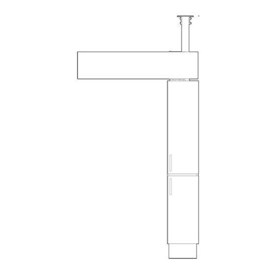
Connector cable Drum house Motor module Control board Interface card Battery set: 2x12V 5,4Ah Corner protectors 6. Dimensions Model Capacity WM-230 230 kg FC-230 230 kg 230-330 IW-230 230 kg 230-500 All measurements (A-F) in centimeters. Integralift 230 – Servicemanual rev2.6... -
Page 8: Replac Cing Lifting S Strap
The double overlap of the lifting strap (registers end stop) must face towards drum. Attach the liftstrap to the sling bar. (see next page) Test Integralift functionality and mount rear cover. Register the change of lifting strap in the log. Integralift 230 – Servicemanual rev2.6... -
Page 9: Replac Cing The Slin Ng Bar (Sta Arlock Solu Ution)
2. Unscrew the screw and place the new sling bar in the lifting strap. 3. Screw in the bolt, press attach new Starlock fastener to end. 4. Register the change of sling bar / (or lift strap) in the log. Integralift 230 – Servicemanual rev2.6... -
Page 10: Replac Cing Fuses On Contro Ol Board Or R Battery C Able
Fuses o on Contro ol Board o or Battery y Cable 1. O On Board:U Use original fuses from m Integra: Lit ttelfuse Min niblade 5A ( Brown), 10A A (Red) 2. O On Cable: U Use origina l fuses from... -
Page 11: 10 0. Replac Cing Drum House
Re-position n top cabine et and rear c cover. 7. T Test Integra alift function nality. Register the e change of f drum hous se in the log Integralift 2 230 – Servicem... -
Page 12: Replac Cing Motor Module
NB: Ma ke sure no wires get tr rapped. Re-position n rear cover r and top ca abinet. 6. T Test Integra alift function nality. Register the e change of f motor mod dule in the l Batteries Contr rol board w... -
Page 13: 12 2. Trouble Eshooting
3. Motor switch activated (green side visible)? ii. Test with new remote control iii. Test with new interface card iv. If Integralift is still not working, contact Integra or your local supplier b. If no (Does not beep): i. Check connections in the following order: 1. - Page 14 Check that fastening to room features is done correctly and all screws sufficiently tightened. b. Check that noise disappears during usage, if not; contact Integra or your local retailer. 2. Is the noise coming from bearings between the jibs and/or structure? a.
-
Page 15: End Co Ontrol, Insta Allation - In Ntegralift
User manual Status: X = OK, 1 = Observation needed, 2 = Immediate repairs needed, 3 = Withdraw from usage Weight Tested with 1,0 Max patient weight for 20minutes Date: Control performed by: Tel nr: www.integracp.no Integralift 230 – Servicemanual rev2.6... - Page 16 Service Partner: Supplier: Producer: Integra Care Products AS Darres gate 22B 0175 Oslo - Norway Tel nr: +47 21 98 26 84/ Manager:+47 90 19 87 99 E-mail: post@integralift.net www.integralift.net Integralift 230 – Servicemanual rev2.6...
Need help?
Do you have a question about the Integralift 230 and is the answer not in the manual?
Questions and answers