
Related Manuals for Beckhoff C6525


Summary of Contents for Beckhoff C6525
- Page 1 Installation and Operating instructions for Built-in Industrial PC C6525 Version: 1.1 Date: 2021-11-15...
-
Page 3: Table Of Contents
Unpacking Installation of the PC in the control cabinet Earthing measures Mounting of the Industrial PC Power Supply Connection Beckhoff power supply technology Pin assignment of the connector Fitting the cable Material for assembling the connectors Assembling the connectors Connecting Power Supply... - Page 4 Table of contents Troubleshooting Fault correction Beckhoff Support & Service Beckhoff branches and partner companies Beckhoff Headquarters Beckhoff Support Beckhoff Service Assembly dimensions Appendix Technical data Approvals FCC: Federal Communications Commission Radio Frequency Interference Statement FCC: Canadian Notice 6525...
-
Page 5: General Notes
© This documentation is copyrighted. Any reproduction or third party use of this publication, whether in whole or in part, without the written permission of Beckhoff Automation GmbH, is forbidden. Description of safety symbols The following safety symbols are used in this operating manual. They are intended to alert the reader to the associated safety instructions. -
Page 6: Basic Safety Measures
General Notes Basic safety measures Only switch the PC off after Before the Industrial PC is switched off, software that is running must closing the software be properly closed. Otherwise it is possible that data on the hard disk is lost. Please read the section on Switching the Industrial PC on and off. -
Page 7: Operator's Obligation To Exercise Diligence
General Notes Operator’s obligation to exercise diligence The operator must ensure that • the Industrial PC is only used for its intended use (see also Product Description chapter). • the Industrial PC is in a sound condition and in working order during operation. -
Page 8: Product Description
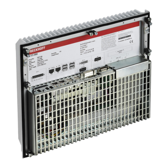
Product Description Product Description Appropriate Use The 6525 Industrial PC is designed for mounting in control cabinets or in the rear panel of a control or console housing for machine and plant engineering applications. The heat sink of the IPC is thereby fed to the outside through a suitable cut-out in the panel of the control cabinet. -
Page 9: Interfaces
Product Description Interfaces Interfaces to the X106 X108 X102 X103 X109 X110 X111 Industrial PC X107 X105 Serial interface RS 232 The Industrial PC has one serial interfaces, COM1 (X102), using the type COM1 RS232, which is brought to a 9 pin SUB-D plug connector. DVI (Digital Visual Interface) The DVI connection (X103) is used for transferring the video signal. -
Page 10: Installation Instructions
4. Please keep the associated paperwork. It contains important information for handling the unit. 5. Check the contents for visible shipping damage. 6. If you notice any shipping damage or inconsistencies between the contents and your order, you should notify Beckhoff Service. 6525... -
Page 11: Installation Of The Pc In The Control Cabinet
Installation Instructions Installation of the PC in the control cabinet The 6525 Industrial PC is designed for mounting in control cabinets for machine and plant engineering applications. The ambient conditions specified for operation must be observed (see chapter Technical data). Preparation of the control The control cabinet must be provided with the relevant cutout (see chapter cabinet... -
Page 12: Mounting Of The Industrial Pc
Installation Instructions Mounting of the Industrial PC The Industrial PC is mounted with clamping levers. Mounting of the Industrial PC with clamping levers Clamping levers For installation the Industrial PC proceed as follows: Release clamping levers, Insert the Industrial PC into the cutout. Release the clamping levers with a No. -
Page 13: Power Supply Connection
However, over time this reduces the service life of the battery. The new Beckhoff power supply technology approach addresses this problem and now offers the user the option of switching the PC off without the need for using the battery, thereby reducing the load on the battery. -
Page 14: Pin Assignment Of The Connector
Installation Instructions In order to maintain a screen display for the Industrial PC in the event of a power failure, the power supply unit is equipped with a UPS output for connecting a Control Panel. This enables a power failure to be visualised and displayed to the user. -
Page 15: Fitting The Cable
Installation Instructions Fitting the cable Wiring in accordance with Fit the cables for the power supply of the Industrial PC, the connection of wiring diagram the battery pack as well as the connection of the power-switch in accordance with the wiring diagram, using the included material for assembling the connectors. -
Page 16: Connecting Power Supply
Installation Instructions Connecting Power Supply The external wiring consists of the connection of the power supply, the battery pack (optional) and the connection of customised components for shutting down the PC. Cable Cross Sections Note cable cross sections, For the connection of the power supply, wiring with a cable-cross-section avoid voltage drop! of 1.5 mm must be used. -
Page 17: Wiring Diagram
Installation Instructions Wiring diagram Wiring according to the wiring diagram (the circuit of PC_ON and Power- Status is symbolical): Wiring diagram external switch and power supply The battery pack can only be connected when the Industrial PC is provided with an integrated UPS (order option). Note 6525... -
Page 18: Connecting Devices
Installation Instructions Connecting devices The power supply plug must be withdrawn! Warning Please read the documentation for the external devices prior to connecting them. During thunderstorms, plug connector must neither be inserted nor removed. When disconnecting a plug connector, always handle it at the plug. Do not pull the cable! Connecting cables The connections are located at the top of the Industrial PC and are... -
Page 19: Operating Instructions
Operating Instructions Operating Instructions Please also refer to chapter General Notes. Switching the Industrial PC on and off Switch on The Industrial PC does not have its own mains switch. The Industrial PC will start when the equipment is switched on, or when it is connected to the power supply. -
Page 20: Maintenance
Operating Instructions Maintenance Please also refer to chapter General Notes. Cleaning the Industrial PC Switch off the Industrial PC and all connected devices, and disconnect the Industrial PC from the power supply. Danger The Industrial PC can be cleaned with a soft, damp cloth. Do not use any aggressive cleaning materials, thinners, scouring material or hard objects that could cause scratches. -
Page 21: Ups Software Components (Optional)
The driver software comes with a detailed help function. System The help files can be called up either directly from the configuration register by clicking the Help button, or under via Start > Programs > Beckhoff > UPS software components. 6525... -
Page 22: Troubleshooting
Nothing happens after the Industrial No power supply to the Industrial Check power supply cable. PC has been switched on Other cause. Call Beckhoff Service. The Industrial PC does not boot Setup settings are incorrect. Check the setup settings. fully Other cause. -
Page 23: Beckhoff Support & Service
Please contact your Beckhoff branch office or partner company for local support and service on Beckhoff products! The contact addresses for your country can be found in the list of Beckhoff branches and partner companies: www.beckhoff.com You will also find further documentation for Beckhoff components there. -
Page 24: Assembly Dimensions
Assembly dimensions Assembly dimensions The assembly of the unit must take place with the orientation diagrammed here. Warning Industrial PC C6525 All dimensions are in mm. rear view side view top view 6525... -
Page 25: Appendix
Appendix Appendix Technical data Industrial PC 6525 Dimensions (W x H x D): 330 x 275 x 82 mm Weight: 4.74 kg Do not use the PC in areas The Industrial PC may not be used in areas of explosive hazard. of explosive hazard The following conditions must be observed during operation: Ambient temperature:...
Need help?
Do you have a question about the C6525 and is the answer not in the manual?
Questions and answers