ELECRAFT K4 Operating Manual
Hide thumbs
Also See for K4:
- Introduction manual (41 pages) ,
- Programmer's reference manual (35 pages) ,
- Operating manual (98 pages)
Table of Contents
Advertisement
Quick Links
Advertisement
Table of Contents

Subscribe to Our Youtube Channel
Related Manuals for ELECRAFT K4


Summary of Contents for ELECRAFT K4
- Page 1 ELECRAFT K4 OPERATING MANUAL Rev D6, May 3, 2024...
-
Page 2: Table Of Contents
Contents INTRODUCTION ............................... 6 USING THE BUILT-IN OPERATING MANUAL ........................ 6 Key to Text Styles ..............................7 K4 TRANSCEIVER OVERVIEW ............................7 INSTALLATION INSTRUCTIONS............................. 9 Orientation and Air Flow ............................9 Power Supply ................................. 10 Interfacing to Station Equipment ..........................10 Getting Started .............................. - Page 3 KEY OUT ................................. 17 PADDLE .................................. 18 KEY ..................................18 ACC ..................................18 II. FRONT PANEL REFERENCE ............................20 USING TAP, HOLD, and TOUCH CONTROLS ....................... 20 Using Tap and Hold Switch Functions........................20 Using Touch Controls ............................. 20 Multi-Function Knobs ............................21 FRONT PANEL OVERVIEW ............................
- Page 4 S-Meters ................................33 Transmit Bar Graphs .............................. 33 Filter Graphic ................................. 33 K4D Icon ................................. 34 Status Area................................34 Transmit Icons ............................... 35 Receive Icons ................................. 36 Panadapter ................................36 Mini-Pan ................................36 Alphanumeric Keyboard ............................37 VFOs AND RIGHT-SIDE CONTROLS ..........................37 VFO A ..................................
- Page 5 ANTENNA SELECTION ..............................51 TX Antenna ................................51 RX Antennas ................................51 Antenna Names ..............................53 Using RX ANT OUT ..............................53 Listening to Signals Below 1 MHz .......................... 54 OPERATING MODES ..............................54 CW MODE ................................55 VOICE MODES ................................ 58 Voice Monitoring ..............................
- Page 6 Dual Receive with K4D/K4HD ..........................78 DIVERSITY MODE ..............................79 HDR RECEIVE (K4HD) ..............................80 AUDIO EFFECTS (AFX) ..............................80 DIGITAL VOICE RECORDER (DVR) ..........................80 Recording and Playing Receive Audio ........................80 DVR Transmit Messages ............................81 USING THE STATUS DISPLAY ............................82 Status Display Functions ............................
-
Page 7: Introduction
INTRODUCTION USING THE BUILT-IN OPERATING MANUAL This is a printable copy of the Elecraft K4 Operating that is programmed in the K4 Transceiver. Please read the fully illustrated short-form manual, Introduction to the Elecraft K4, to become familiar with control and connector locations. -
Page 8: Key To Text Styles
In addition to its extensive front panel controls, the K4 has full mouse support, and can also be controlled by an Elecraft K-Pod. - Page 9 Since the K4 is an SDR, Elecraft can provide updates to its signal processing algorithms with software changes rather than by adding new hardware. This ensures that the K4 can take advantage of new modes, bands, or other features in the future.
-
Page 10: Installation Instructions
A basic K4 can be upgraded to a K4D by installing the KRX4 option. Similarly, a K4D can be upgraded to a K4HD by installing a KHDR4 module. Other internal options and external accessories are applicable to all three models, including a wide-range ATU (KAT4), MH4 microphone, SP4 external speaker (1 or 2). -
Page 11: Power Supply
30 amp supply is recommended. For 10 W use, a 5 amp supply will suffice. NOTE: If use of a switching supply results in low-pitched repetitive noise or other artifacts when monitoring your K4's signal in another receiver, consider using a well-regulated and filtered linear supply. -
Page 12: Getting Started
Getting Started Once your K4 is installed and you're ready to operate, you can get started in one of two ways: (1) read the FRONT PANEL REFERENCE section to learn about each of the controls, or (2) jump to OPERATING INSTRUCTIONS section, which is more procedural in nature. -
Page 13: 12 Vdc In
(such as the Elecraft KPA1500), connect its transmit output sample port to TX SMPL IN. Signal level and calibration details to be determined. Transmit IMD optimization can also be enabled for use with the K4's internal amplifier stages. XVTR IF IN / RX ANT 2... -
Page 14: Rx Ant Out
"PC". There is an additional type A jack on the front panel. Any of the type A jacks may be used with a keyboard, mouse, memory device, or Elecraft K-Pod. Wireless adapters may be used. Each rear USB-A jack can provide up to 400 mA max to peripheral devices. -
Page 15: Video
LCD. See Ext. Monitor Function SCREEN AND TOUCH CONTROLS. REF IN A 10 MHz reference signal may be connected to this jack. The K4's internal reference oscillator will lock to this signal when present. Also see ER100 (Error Messages). -
Page 16: Line In
This is an analog audio output (stereo; nominally 600 ohms) for connection to computers or other station equipment that obtain receive audio from the K4. An example of this is a software application that demodulates data-mode audio signals such as FT8, RTTY, or PSK31, as well as CW signals. -
Page 17: Spkrs
SPKRS Left and/or right speaker audio (nominally 4 to 16 ohms). 1 or 2 non- powered speakers such as the Elecraft SP3 or SP4 may be connected to this jack. Powered speakers may also be used, though attenuation may be needed between the speaker jack and the external speakers to prevent overdrive. -
Page 18: Mic
RS-232 This DE9 connector provides a true-RS232 COM port that can be used for remote control of the K4. The K4 can also emit Auto-Info (AI) frequency data on this port for use with external devices such as antenna controllers. -
Page 19: Paddle
Accessory IO connector (DE15). This connector provides a number of input signals for use in controlling the K4, as well as outputs for controlling amplifiers, antenna switches, and other external equipment. The list below summarizes these functions;... - Page 20 DIGOUT0; low-power external transverter select K4 "power on" signal or TX Inhibit input (see TX Inhibit Mode) Power On; pull to ground (0 V) for 0.2 to 1.0 sec to turn K4 on, then release BAND2 OUT; BAND0-BAND3 outputs provide 4-bit parallel band indication KEY OUT LP;...
-
Page 21: Ii. Front Panel Reference
FRONT PANEL OVERVIEW section, which follows. Using Tap and Hold Switch Functions Each of the K4's physical switches has both a tap function (white label) and a hold function (yellow label). A tap is a brief press, while a hold is any press longer than about 1/2 second. -
Page 22: Multi-Function Knobs
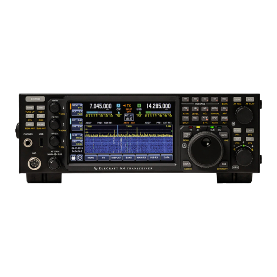
FRONT PANEL OVERVIEW A large (7" diagonal) color LCD forms the heart of the K4's user interface. Most of the screen is dedicated to either a single panadapter (associated with VFO A or VFO B), or split between dual panadapters (centered below the VFO A and VFO B displays, respectively). -
Page 23: Front-Panel Connectors
Front-Panel Connectors There are three connectors on the front panel: The front mic jack is an Elecraft standard 8-pin type. It is compatible with the Elecraft MH4 and other K3/K3S-compatible microphones. Bias, gain, and mic PTT/UP/DOWN controls are configured using <TX>... -
Page 24: Left-Side Controls
POWER Tap [POWER] to turn the K4's power on or off. NOTE: Always turn the K4 off using its power switch. If you need to turn off the power supply as well, wait until the K4 has completely powered down. -
Page 25: Tune Lp
XMIT Tap [XMIT] to place the K4 in transmit mode. This is the equivalent of holding a mic PTT button or asserting any of the other PTT lines (e.g., at the PTT IN jack). Tap [XMIT] a second time to exit transmit mode. -
Page 26: Atu Tune
Each time you transmit, the K4 makes sure that the stored LC settings closest to your operating frequency are used. For this reason, after you move the VFO and transmit, you may hear relays switching briefly (~10 ms). -
Page 27: Atu
QSK is especially useful in contesting, DXing, and high-speed CW QSOs. The K4 actually allows received signals to be heard in this way even with QSK turned off, as long as the radio is in [VOX] mode and the {XMTR} <DLY>... -
Page 28: Ant
[SUB ANT] to select one of the available antennas for use with the sub receiver. See ANTENNA SELECTION. MULTI-FUNCTION CONTROLS The K4 has three multi-function controls, each handling a group of related functions: XMTR, FILTER, and RF/SQL. The knobs incorporate... -
Page 29: Xmtr Knob
push-button switches which are tapped or held to select among parameters to adjust. Each knob is accompanied by two buttons on the LCD. These buttons each have two labels, one of which is currently available for adjustment. The button in each pair that is selected is highlighted by a colored rectangular indicator: orange for XMTR, blue or green for FILTER, blue or green for RF/SQL. -
Page 30: Filter Knob
used with a CW keyer paddle). Tap a button a second time to alternate between its two functions. {XMTR} <PWR> normally sets the power in watts. If MENU:XVTR Out Test is in effect, or an external transverter band is in use, the value will be in milliwatts (mW). -
Page 31: Rf/Sql Knob
CUT>. Tap a button a second time to alternate between its two functions. Tapping the {FILTER} knob changes the LCD button selection. Holding the knob selects [NORM], a per-mode nominal passband. RF/SQL Knob Rotate {RF/SQL} to adjust RF gain or squelch. Tap the upper LCD button to adjust main receiver RF gain or squelch (blue indicator). -
Page 32: Af/Sub Knob (Af Gain)
AF/SUB Knob (AF Gain) The inner concentric knob, {AF}, sets main receiver AF gain. The outer concentric knob, {SUB}, normally sets sub receiver AF gain. It can also be configured to control left/right channel audio balance (see RF Gain, Squelch, and Main/Sub Balance). -
Page 33: Primary Function Buttons
Primary Function Buttons Seven buttons along the lower edge of the display provide access to functions used frequently to configure and operate the K4: <MENU>, <Fn> (special functions), <DISPLAY>, <MAIN RX>, <SUB RX>, and <TX>. For a full description, see PRIMARY FUNCTIONS. -
Page 34: Rit And Xit Icons
Normally the K4 transmits on VFO A, so these bar graphs will appear on the left. In SPLIT mode, the K4 transmits on VFO B, so they appear on the right. This serves as a clear reminder to the operator about whether SPLIT is in effect or not. -
Page 35: K4D Icon
The K4D model includes a fully independent second receiver module (KRX4), with its own set of band-pass filters, preamps, and attenuators. The K4 will use this module whenever possible to maximize receive performance. When the KRX4 module is in use, the K4D icon (to the right of the RIT/XIT box) will illuminate. -
Page 36: Transmit Icons
select a different status display, such as your callsign and time, or supply voltage/current/power output/SWR, or main/sub signal levels in relative dB. See USING THE STATUS DISPLAY for full details. Transmit Icons Icons associated with the transmitter are orange. As shown below, they are located above and below the RIT/XIT offset box. -
Page 37: Receive Icons
Receive Icons Below each S-meter is a collection of icons pertaining to that receiver's configuration. These indicate the current settings of the preamps (PRE), attenuators (ATTN), noise blanker (NB), noise reduction (NR), audio peaking filter (APF), manual or automatic filtering (NTCH), automatic gain control (AGC), and receive antenna (e.g., ANT1 or RXANT1). -
Page 38: Alphanumeric Keyboard
In FSK and AFSK modes, the mini-pan cursor identifies the mark tone, while a dotted line shows the space tone. Alphanumeric Keyboard An alphanumeric keyboard is displayed when text entry is required, such as when entering your callsign (see Status Area) or CW/FSK/PSK message text Messages). -
Page 39: Spot And Auto-Spot
digits, there are three special functions: [X] (delete last-entered digit), [.] (decimal point), and [<-] (enter). The keypad can be used to enter data in some menu entries, such as XVTR Band <n> RF. In this case a small keypad icon will appear to the right of the parameter edit field. -
Page 40: Vfo Controls
Next, enter the desired frequency using the numeric keypad (Numeric Keypad). Entering 1 or 2 digits is interpreted as MHz; 3 or more digits as kHz. You can optionally include one or two decimal points during frequency entry (MHz and kHz). To scan a selected range, you'll first need to create a frequency memory with VFO A and B as the start and end points. -
Page 41: Receiver Controls
both main and sub RX are placed on the frequency of VFO A (see DIVERSITY MODE). Sub receiver AF gain is controlled by the outer concentric knob to the left of the LCD. VFO B/sub can be set to a different band from VFO A/main (see DUAL RECEIVE). -
Page 42: Frequency Memory Controls
FREQUENCY MEMORIES. Receive Audio Record/Playback The K4 can record and play received audio. Both main and sub audio are recorded and played if the sub receiver was on during record. To bring up receive audio record/play controls, hold [AF REC] PLAY]. -
Page 43: Rit/Xit And Clr
RIT/XIT and CLR Tap [RIT] to turn on Receive Incremental Tuning, then rotate the OFS (offset) knob below the switch to tune in a signal. RIT offsets only your receive frequency, not transmit. It is especially helpful when CW stations call you off-frequency. Similarly, [XIT] can be turned on to adjust only your transmit frequency. -
Page 44: Iii. Operating Instructions
** Indicates a feature that is still in development. PRIMARY FUNCTIONS Before putting your K4 on the air, you should become familiar with the primary function buttons located at the lower edge of the LCD screen. These functions, used for basic setup of transmit, receive, and panadapter operation, are described below. - Page 45 USB A jacks. Also see MENU:Screen Cap File. Note: There is no "eject" control for the flash drive, as required on some computers. The K4 mounts/unmounts the flash drive (from a software perspective) as needed.
-
Page 46: Display
from a USB flash memory device. In the latter case, the flash memory device must be pre-loaded with the intended software release. DX LIST (F13) Tap <Fn>, then <DX LIST> to bring up a complete list of countries and prefixes. Scroll the list using VFO A or the up/down arrow buttons. (The list is updated periodically in conjunction with software updates.) To search for a country or prefix, tap the magnifying glass button. -
Page 47: Band
LCD/EXT display target selector; (2) A/B panadapter target selector; and (3) parameter adjustment. In the simplest case, with only a VFO A panadapter in use and no external display, the LCD/EXT target can be set to LCD, and the A/B target can be set to (A). -
Page 48: Sub Rx
VFO A, normally, but you can also offset VFO B by any desired amount, which will be preserved as VFO A is tuned. <AFX>: Turns audio effects on or off. Holding this button selects the AFX mode: DELAY (simulated stereo) or PITCH (low-to-high audio pitch mapping from left to right when used with stereo headphones or dual external speakers). - Page 49 <MIC CFG>: Sets up front/rear mic gain and bias. For the front mic only, configures buttons (NONE or UP/DN). For an Elecraft MH4 mic, turn bias on, set preamp gain to 0, and enable all buttons. Mics with low-output elements may require higher preamp gain settings.
- Page 50 and PSK modes as well when used conversationally with the internal keyer and message memories. <PDL>: Selects keyer paddle normal (jack tip = DOT) or reverse (tip = DASH). <IAMB>: Selects the desired Iambic keying mode. The default is mode A (IAMB A), which is generally considered easier by many CW users.
-
Page 51: Band Selection
Also see DATA MODES. BAND SELECTION The K4 provides several ways to select the band and operating frequency: • Tap <BAND>, then tap the button corresponding to the desired band. Tapping a given band button more than once cycles through three band-stacking registers, recalling recently used frequencies and modes. -
Page 52: Antenna Selection
ANTENNA SELECTION TX Antenna To select a transmit antenna, tap [ANT]. An orange text icon near the upper middle of the LCD shows this selection. Both receivers default to this antenna as well, as indicated by their separate antenna icons under the main and sub S-meters. - Page 53 The K4D adds a second band-pass filter unit and a second A- to-D converter, allowing the sub receiver to use a different antenna from main. These modules can be installed in a basic K4 at any time, converting it to a K4D.
-
Page 54: Antenna Names
ATU and TX low-pass filters. Since it also passes through the T/R switch, it is inherently protected from the K4's own transmit signal. In order for RX ANT OUT to be active, both receivers must be configured to use receive-only antennas (RX ANT IN 1 or XVTR IN/RX ANT IN 2). -
Page 55: Listening To Signals Below 1 Mhz
Listening to Signals Below 1 MHz Signals below about 1 MHz will be attenuated when the receiver is using the transmit antenna path (i.e., when the RX antenna is set to the "=TX" setting, or to an ATU antenna also being used by the transmitter). -
Page 56: Cw Mode
RS-232. A paddle directly connected to the PADDLE input takes advantage of the K4's built-in keyer function, eliminating the need for an external keyer. This also allows your own CW to be displayed in the text- decode window. You can use the paddle to transmit in FSK and PSK modes, as well, by sending CW characters. - Page 57 CW Messages ) The K4 provides 2 banks of 4 message buffers each for use in CW, PSK, and FSK modes. These messages can be backed up using the BACKUP function (tap <Fn>, then hold <BACKUP>).
- Page 58 CW mode. CW Text Decode The K4 can decode transmitted and received CW signals, displaying the text in multiple lines below the panadapter. This can be useful for learning CW, for copying higher code speeds, or even for the benefit of a non-CW-operator looking over your shoulder.
-
Page 59: Voice Modes
TX line. VOICE MODES The K4 can obtain voice audio from the front mic, rear mic, or LINE IN (analog or digital), or a combination of these. These selections are made by tapping <TX>, then <MIC INP>. Some operators prefer to use a rear-panel mic to eliminate clutter at the front panel. -
Page 60: Mic Gain And Compression Settings
• Hold [TEST] to put the K4 in TX TEST mode, so you won’t be transmitting. The TX icon will change to TX Test. • Set {XMTR} <MIC> high enough to hear your voice (typically 10-20). • Press your mic’s PTT switch or tap [XMIT]. -
Page 61: Voice Mode Vox Setup
• ANTIVOX sets VOX immunity to receiver audio coming from the speaker(s). With the mic closer to the speaker than normal, increase ANTIVOX until the K4 doesn’t switch to TX mode when listening to a strong signal. • Adjust the VOX delay using {XMTR} <DLY>. A longer value will keep the K4 in transmit mode for a longer period of time, allowing for pauses in speech. -
Page 62: Data Modes
(while PTT is asserted). DATA MODES The K4 has four data modes: DATA, AFSK, FSK, and PSK. These are further described below. There are also manual sections dedicated to setup requirements for... -
Page 63: Data Mode Connections
TX line. You can also use the CW message memories, [M1]-[M4], to send text. Data Mode Connections The K4 provides a rich set of I/O connections for use with computer- based data modes, including analog LINE IN/LINE OUT (LINE... -
Page 64: Data Mode Line In Gain, Alc, And Monitor Level
To select a data mode, tap [MODE] or the mode icons adjacent to each VFO to bring up the mode button group. The following modes are available: • DATA (generic) can be used for all audio-based data modes, including FT8, JT modes, PSK31/PSK63, MFSK, AFSK, etc. The VFO displays the suppressed-carrier frequency, just as when SSB modes are used for data. -
Page 65: Receiver Settings
(Note to those who have used a K3: The K4's bar graphs have twice as many bars as the K3's for a given activation level. The K3 manual suggested "4 bars" as the right level for data modes, which would translate to 8 bars on the K4. - Page 66 station's noise floor. Lower gain or added attenuation will reduce the possibility of receiver overload in the presence of extremely strong signals. • Preamp (PRE): Tap [PRE] to cycle through preamp OFF, PRE1, and PRE2. PRE2 provides the highest gain and lowest noise figure on a given band.
- Page 67 The default value for the RF gain controls is 0 (no reduction in RF gain). Counter-clockwise rotation of the knob increases attenuation (reduces gain) from 0 to -60 dB. Some operators prefer to control receiver gain using the RF gain control rather than AF gain control, in order to keep signals from activating AGC.
- Page 68 The following three controls can be used to reduce noise and interference. Note: Since the K4 is an SDR (software-defined radio), new noise remediation algorithms can be added as they become available. • Noise Blanker (NB): Tap [NB] to turn the noise blanker on/off, or...
- Page 69 K4's stereo audio effects. See AUDIO EFFECTS (AFX). • All models of the K4 include simultaneous dual receive on any two HF-6 meter bands. For details on sub receiver use, see DUAL RECEIVE.
-
Page 70: Transmitter Settings
This section covers general transmit topics. For specific modes, OPERATING MODES. Transmitter Configuration Prior to transmitting with the K4, you should familiarize yourself with the transmit configuration functions (see primary function button). These are used to configure TX EQ, LINE IN, microphones, and various per-mode settings. -
Page 71: Transmit Status Indications
CW Messages Transmit Messages. • The K4 provides an ESSB (extended single-sideband) mode for operators who wish to use or experiment with higher-fidelity SSB. Since ESSB increases transmit bandwidth, it should only be used when the operator is certain they're not causing interference to other stations. -
Page 72: Tx And Rx Metering
S-Meters and High-Signal Indications Each receiver (main/VFO A, and sub/VFO B) has its own S-meter. The K4's S-meters always read absolute signal value. This means that for a signal at a given absolute amplitude at the antenna, the S-meter will read the same value regardless of preamp or attenuator settings. -
Page 73: Panadapter
PANADAPTER The K4 supports independent panadapter displays on the LCD and on the external monitor. Both spectrum and waterfall can be customized to the user's requirements. You can select single panadapter mode (VFO A or B) or dual panadapter mode (VFO A and B). -
Page 74: Using Panadapter Controls
automatically adjusting the VFO frequency. In FSK and AFSK modes, the mini-pan cursor identifies the mark tone, while a dotted line shows the space tone. Mouse Icons A mouse icon will appear in each panadapter window whenever a mouse is plugged in. See image below, which shows the VFO A panadapter window. -
Page 75: Panadapter Controls List
• Tap the <DISPLAY> primary function button. This brings up a secondary function button row comprised of all panadapter controls. In the row above these, three controls will be shown: (1) LCD / & / EXT select buttons; (2) panadapter A / & / B select buttons; (3) parameter adjustment field. - Page 76 <WTRFALL>: Sets waterfall height (% of total panadapter height). A higher percentage displays a taller waterfall, useful for seeing more signal history. A lower number provides more spectrum height, making real-time signals more visible. <NB>: Turns panadapter noise blanker on/off and sets the blanking threshold.
-
Page 77: Panadapter Cursor Modes
<FIXED>, <TRACK>, <SLIDE> (etc.): This function controls how the panadapter display moves with respect to the VFO cursor. The different modes are described below. <FREEZE>: Suspends the panadapter spectrum and waterfall. This is useful in conjunction with screen capture to a file on a flash drive (see Fn). -
Page 78: Tap-To-Qsy
A or B VFO. DUAL RECEIVE All K4 models have dual-receive capability, which allows the main and sub receivers to be used simultaneously, even on two different bands. In all cases, the main receiver is associated with VFO A, and the sub with VFO B. -
Page 79: Dual Receive With K4D/K4Hd
The K4D and K4HD models include a fully independent second receiver module (KRX4), with its own set of band-pass filters, preamps, and attenuators. If this module is installed, the K4 will use its filtering to maximize receive performance. For example, if the receivers are on two different bands, the KRX4 module will be turned on, so that both bands will have the benefit of band-pass filtering. -
Page 80: Diversity Mode
ANTENNA SELECTION. • The K4 must be configured to allow stereo audio. Diversity requires either headphones or dual external speakers. If you're using dual external speakers, make sure that MENU: Speakers, External is set to... -
Page 81: Hdr Receive (K4Hd)
This section will be completed in conjunction with release of the K4HD model (in progress). AUDIO EFFECTS (AFX) Since the K4 has both left and right audio channels, it can provide simulated stereo or other effects to reduce operating fatigue. This requires the use of stereo headphones or dual external speakers. -
Page 82: Dvr Transmit Messages
Recorded audio may be played back while in transmit mode, allowing you show stations what they sounded like at your end. However, the most common use of receive recording is to re-listen to a call or exchange you may have missed the first time. To begin recording receive audio, hold REC]. -
Page 83: Using The Status Display
Status Display Functions <DATE/TIME>: This is the default status display, showing UTC date and time. If your K4 has an internet connection, the date and time will normally be accurate to within approximately 1 second. Hold <SET>... -
Page 84: Frequency Memories
FREQUENCY MEMORIES The K4 provides 200 general-purpose frequency memories, as well as 4 Quick Memories per band. General-Purpose Memories To store VFO A and B frequencies in a general-purpose memory: •... -
Page 85: Active Memory Recall
• Tap [M1]-[M4]. This will also dismiss the frequency memory window. USING SPLIT Normally, VFO A is used for both receive and transmit. In SPLIT mode, the K4 transmits on VFO B. SPLIT is useful if you're working a DX pileup using VFO A to listen to the DX station, with VFO B as your calling frequency, and have the sub receiver turned off. -
Page 86: Internal & External Transverters
• the yellow delta-F LED (∆f) turns on INTERNAL & EXTERNAL TRANSVERTERS The K4 provides 12 programmable transverter bands. Each can be configured for the desired RF band edge (0-99999 MHz), IF (0-53 MHz), mode (off, external, or internal), and oscillator/multiplier chain correction (+/- 99.999 kHz). -
Page 87: Dual Transverter Operation
Dual Transverter Operation Two external transverters can be connected to the K4 for simultaneous use on two different bands. Set up VFO A for one band, and select either RX1 (RX ANT 1) or RX2 (XVTR IN) as the antenna. Set up VFO B for the other band, using the opposite antenna. -
Page 88: Macro Programming
Other apps and platforms may be available in the future. A K4 used as a client can be disconnected from the server, when desired, to use the radio with local antennas. The K4/0 is a control-only device (no RF),... - Page 89 TCP and UDP client protocol as discussed later in this section. The steps needed to set up your K4 as a server or client are detailed below. In the server case, you'll also need to configure your router for port forwarding.
- Page 90 Once port forwarding and server setup are completed, no further action is needed on the server side. Clients will be able to access your K4 anytime it is powered up and has an Ethernet connection.
- Page 91 2. Install version R36.BETA1 (or later) software on the server K4. Earlier versions do not support remote front-panel emulation. 3. On the K4 operating screen, you'll see a new "globe" button near the "?" button: Whenever the globe button is grayed out, as above, the K4 is not acting as a client or as a server.
- Page 92 DISCLAIMERS: (1) Elecraft is not responsible for any damage that may occur to your server K4 or other equipment due to unsafe operation by you or by third parties. (2) Elecraft is not responsible for unauthorized access to, or manipulation of any radio gear, computing equipment, or data.
- Page 93 Whenever the globe button is grayed out, as above, your K4 is not acting as a client or as a server. Once a connection to a server is established, the globe changes color, and an arrow pointing up is added: 3.
- Page 94 Once you've set up one or more "Available Servers" using the client settings screen, as described above, you can establish a client-to-server connection at any time. If you're using a server K4 other than your own, be sure to obtain permission from the owner and coordinate on operating times.
- Page 95 TBD.) Updating Software on a Remotely Located K4 It is possible to update software on a remote K4 (or change its password and max client setting) without being present at the radio. The automated update process can take from about two to fifteen minutes,...
- Page 96 There are two cases for remote K4 software update (see below). After either method completes, client connections can then be made. • If R36.BETA1 or later is already installed on your server K4, you can perform future updates by first establishing a connection to it from a client device, then executing a "PS89;"...
- Page 97 K4 does not support Ethernet "Wake on LAN" like the KPA1500.) The only way to power up a remote K4 is by pulsing pin 8 of the K4's ACC connector to ground for at least 200 ms, e.g. using a relay or open-drain or open-source transistor.
-
Page 98: Rtty Configuration
(FSK mode). (To be completed.) FT8 / JT / ETC. CONFIGURATION This section provides step-by-step instructions to configure the K4 for FT8, JT65, and similar audio-based, weak-signal modes. In all cases, the K4's DATA mode is used. (To be completed.) -
Page 99: Iv. Menu Listing
IV. MENU LISTING The K4 configuration menu has one level (i.e., it is "flat"). Menu settings are infrequently changed, and most can be left at their factory default values. Using the Menu • Tap <MENU>. Use VFO or the up/down arrow keys to find the desired entry. - Page 100 AGC Decay, Fast AGC-F decay rate. A higher value results in a shorter decay time. AGC Decay, Slow AGC-S decay rate. A lower value results in longer decay time. AGC Hold Time Sets the hold time (applies only to slow AGC). Non-zero hold times are often preferred by SSB operators.
- Page 101 CW TX in SSB Mode If set to YES, CW may be transmitted when the K4 is in LSB or USB mode. This applies to the built-in keyer, external keying, and the "KY<TEXT>;" remote control command.
- Page 102 Ext. Monitor Location Specifies where the external monitor is physically located in relation to the K4 (left, right, above, below). This allows the mouse cursor to be moved between the LCD screen and external monitor in an intuitive way.
- Page 103 AFSK modes use lower sideband by default. This means that the space tone will appear as lower in frequency on the panadapter and mini- pan, even though it is higher in audio pitch.) FSK Polarity Selects the polarity of FSK keying (via the ACC jack or one of the DTR serial control lines).
- Page 104 10 dB) with the LNA (20 dB) for a total of 30 dB gain. This setting should only be used for weak-signal work, with low-noise antennas and/or very low atmospheric noise. Note: The K4 can automatically reduce preamp gain if necessary to avoid front-end overload;...
- Page 105 If the external reference is too low in amplitude for stable operation, a warning will be displayed, and the K4 will continue to use its internal 10 MHz TCXO. Also see ER100 (Error Messages).
- Page 106 Changing the mix is especially useful for SO2V operation (Single Operator, 2 VFOs). In the SO2V case, external host software is typically used to rapidly change the mix settings by using the K4's "MX" remote-control command. For details, refer to your host...
- Page 107 RX Auto Attenuation When the parameter is set to On, the K4 will automatically reduce receiver front-end gain if signals above the usable dynamic range are present. When this happens, the attenuator icons will indicate the amount of inserted attenuation.
- Page 108 (50 Hz bandwidth). RX Dyn. Range Optimization The default value of this parameter (ON) sets up the K4's ADCs (analog-to-digital converters) for best dynamic range. Setting it to OFF will slightly improve sensitivity in the preamp-off case; this may be useful on the highest bands.
- Page 109 Serial RS232: Auto Info Sets the Auto-Info mode for this port. The default is NOR (no auto-info). In the AUTO1 setting, the K4 will emit "IF" command responses on certain control changes including VFOs, mode, and RIT. For further details on auto-info ("AI"...
- Page 110 Serial USB-PC2: Auto Info Sets the Auto-Info mode for this port. The default is NOR (no auto-info). In the AUTO1 setting, the K4 will emit "IF" command responses on certain control changes including VFOs, mode, and RIT. For further details on auto- info ("AI"...
- Page 111 Speakers, External Sets the number of external speakers. When set to 1, the right audio channel amplifier is disabled, and left and right channel audio are mixed together for external speaker use. (Headphone use overrides this, providing full stereo regardless of setting of this menu entry.) Speakers + Phones Set to YES to allow headphones to be plugged in without disabling the speaker(s).
- Page 112 MIC gain or compression settings. NOTE: At the high end of the K4's power output range, it is possible that the peak power shown on the bar graph may be slightly lower than the specified target.
- Page 113 K4 in TEST mode, which keys the K4 and the amplifier without producing RF output. This should be done while one or more large signals are within +/- 5 kHz of the K4's VFO frequency. (Lacking such signals, artifacts are not likely to be heard.)
- Page 114 The other available settings (numeric) will scale the LINE OUT transmit monitor function upward, which is useful for some external devices such as audio recorders. These values will also prevent K4 switch tones from being heard at LINE OUT. TX Monitor Method, Voice When set to Normal, voice monitor audio will be delayed due to DSP signal processing, and will reflect the sound of speech compression, if applicable.
- Page 115 Sets VFO knob counts per turn to 100, 200, or 400 counts. Wattmeter Cal Per-band wattmeter calibration value. Can be adjusted to calibrate the K4's internal wattmeter against a known-accurate external instrument. This should be done on a mid band, e.g. 40/30/20 meters. XVTR Band # Select Specifies the target band number (1-12) for the other XVTR Band menu entries.
- Page 116 In this case, RX ANT 2 (sam as XVTR IN) should be selected for the receive antenna, and both the XVTR IN and XVTR OUT signals connected to the transverter's IF jacks. However, the K4 also provides transverter band setups that automate all the required setup.
-
Page 117: Troubleshooting
One common cause of this is an attached HDMI monitor going into "sleep" mode. Unplug the monitor's vedeo and USB cables, then restart the K4. You may be able to disable the monitor's "sleep mode" using its menu. Another common cause is a defective 15-pin accessory cable. Make sure there are no bent pins or wiring shorts. - Page 118 Check your power supply’s on/off switch, voltage, fuses (if applicable), and DC cabling. The K4 provides both voltage and current monitoring in the time/date/status area of the LCD. Note: The KPA4 module has its own 25 A, 32 V DC Fuse fuse. The recommend replacement is Elecraft E980427 (Littlefuse part number 0287025.PXCN or Digikey F4195-ND).
- Page 119 30 to 50 second r nge. A replacement battery may be obtained from Elecraft. If the replacement runs down quickly as well, a repair to the SBC module may be required. NOTE: TO AVOID DAMAGE TO THE MAIN PROCESSING MODULE, FOLLOW INSTRUCTIONS SUPPLIED WITH THE BATTERY.
-
Page 120: Receive
If you're using a basic K4 with the receivers set to two different bands, the band-pass filters will be bypassed, exposing the receiver to a wider frequency range. -
Page 121: Transmit
S-Meter and signal modulation with noise blanker off: Certain noise conditions can interact with the AGC pulse rejection feature. If you see the S-meter or receive signal being modulated in an unusual way, set MENU:AGC Pulse Reject to OFF or use the noise blanker at a low setting. - Page 122 If power output is low on a given band, check the following: (1) Supply voltage should be ~14 V as measured at the K4's DC input jack. Voltages as low as 11.0 V may be used at reduced output. (2) Operation into low-impedance loads may increase current drain beyond the allowed limit.
-
Page 123: Error Messages
(see Serial I/O menu entries). Try disconnecting everything connected to the ACC and RS232 connectors. Also check VOX gain (unplug mic if necessary). If this does not turn off the TX LED, turn the K4 off for several seconds, then back on. - Page 124 VFO (i.e., you're not in SPLIT). If you then selected a new band for VFO B that's too high in frequency, the low-pass filter would greatly attenuate sub receiver signals. The K4 prevents this from occurring. To get around this limitation, you can do any of the following: (1) turn the sub receiver off;...
- Page 125 (ACC jack). ER12, SET command incompatible with target VFO's mode: external host application or macro has sent the K4 a SET remote control command that does not apply to the current operating mode. ER13, GET or SET command not implemented:...
- Page 126 ER24, VFO B Different Band menu entry is set to NO: By default, the K4 makes sure that both VFOs are on the same band. If VFO B is to be placed on a different band, set MENU:VFO B Different Band to YES.
- Page 127 ER51, High LPA reflected power; check antenna: High SWR seen at the 10 watt stage resulted in excessive reflected power. The antenna may have changed, or you may need to do [ATU TUNE]. If the ATU is off, hold [ATU] to turn it on.
- Page 128 Transmit attempted outside the frequency range of the current ham band. This is only allowed when using the XVTR OUT jack for transmit, or if the K4 has been authorized for MARS use (contact Elecraft for details). ER61, Keyer paddle not allowed:...
- Page 129 ER67-70, Keying input held low at power-up: These alerts let you know if you have a persistent "stuck key" condition when the K4 is turned on. The four alerts cover KEY IN, DOT, DASH, and PTT respectively. Disconnect any connected keying devices and clear the message.
- Page 130 ER150, K4FP missing: The front panel module was not detected on power-up, which may result in multiple issues with basic functionality. This may be due to a dislodged or intermittent USB cable or other hardware problem. Contact Elecraft for possible troubleshooting instructions.
- Page 131 The sub receiver's digital up-converter module was not detected on power-up, which may result in incorrect sub receiver behavior. This may be due to the module being unplugged or other hardware problem. Contact Elecraft for possible troubleshooting instructions. ER154, DAP missing:...
- Page 132 Contact was lost with the main receiver's digital down-converter module, resulting in incorrect main or sub receiver behavior. This may be due to the module being unplugged or other hardware problem. Contact Elecraft for possible troubleshooting instructions. ER173, DDC2 comm failure:...
Need help?
Do you have a question about the K4 and is the answer not in the manual?
Questions and answers