ELECRAFT K4 Introduction Manual
Hide thumbs
Also See for K4:
- Programmer's reference manual (35 pages) ,
- Operating manual (98 pages) ,
- Operating manual (132 pages)

Subscribe to Our Youtube Channel
Related Manuals for ELECRAFT K4


Summary of Contents for ELECRAFT K4
- Page 1 Introduction to the Elecraft K4 (Preliminary) Rev. A-7, Sept. 23, 2020 Copyright 2020, Elecraft, Inc.
-
Page 2: Table Of Contents
TABLE OF CONTENTS OVERVIEW ........... 3 MINI-PAN TUNING AID ....... 22 INSTALLATION ..........4 TEXT DECODE/ENCODE ....... 23 REAR PANEL CONNECTORS ......5 MENU ............25 POWER ON/OFF ........... 6 ANTENNA SELECTION ......... 26 DISPLAY ............7 ANTENNA ICONS ........27 BUILT-IN OPERATING MANUAL ..... 8 ANTENNA CONTROLS ......28 CONTROLS .......... 9 ANTENNA SWITCH CONFIGURATION ..29 BAND SELECTION . -
Page 3: Overview
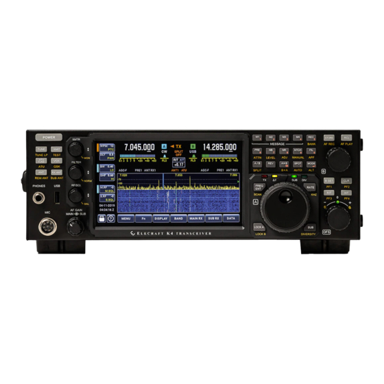
OVERVIEW This short-form manual is intended as an introduction to the K4, providing the essential information you’ll need to get on the air. Refer to the Elecraft K4 Owner’s Manual for additional details on all topics. NOTE: All text and illustrations are preliminary and subject to change. The Elecraft K4 is a high-performance, direct-sampling software-defined radio (SDR). It covers the 160 ~ 6 m bands, with continuous receive from 100 kHz ~ 54 MHz. 10 W and 100 W models are available. It can be used with internal or external transverters to cover bands above 6 meters. Among the K4's notable features: Large color touch screen, as well as support for an external HDMI monitor; extensive, easy to use controls; rich analog and digital connectivity; dual receive (all models); built-in data modes, and wide-range automatic antenna tuner. The K4's compact size and weight, combined with 11-15 VDC operation and low current drain, make it suitable for field, travel, or home station use. Since the K4 is an SDR, Elecraft can provide updates to its signal processing algorithms with software changes rather than by adding new hardware. This ensures that the K4 can take advantage of new modes, bands, or other features in the future. Since it uses direct sampling, signals are digitized right at the receiver inputs, and the transmitter's amplifier chain is also driven by a digitized signal. Older SDR architectures digitized signals at a low intermediate frequency (IF), resulting in poor suppressions of down-conversion or up-conversion images. There are three models: the basic K4, with one set of receive filters and one analog-to-digital converter (ADC); the K4D, which adds a second set of receive filters and a second ADC; and the K4HD, which adds a superheterodyne front end that can be enabled when needed to provide even greater dynamic range. The superhet module uses high-performance, narrow-band crystal filters. All K4 models provide simultaneous dual receive on the same or different bands/modes, though the additional receiver module in the K4D and K4HD (KRX4) improves signal handling during dual-receive operation on different bands. The second receiver also permits diversity reception, i.e., the use of different antennas for the two receivers to counteract fading (QSB). A basic K4 can be upgraded to a K4D by installing the KRX4 option. Similarly, a K4D can be upgraded to a K4HD by installing a KHDR4 module. Other internal options and external accessories work with all models, including a wide-range ATU (KAT4), MH4 microphone, SP4 external speaker (1 or 2). -
Page 4: Installation
INSTALLATION CAUTION: Ground your K4 properly before operation. For suggestions, see www.arrl.org/grounding. ESD and Lightning Protection: Even though the the K4 has extensive internal protective circuitry, external protection against lightning strikes is strongly recommended, especially in lightning-prone areas. During storms and when the station is not in use for an extended period, disconnect ALL equipment from the radio, including antennas, the power supply, routers or hubs, and computers. Ethernet, USB, and RS232 cables are a frequent source of damaging surge voltages. Orientation and Air Flow: Provide at least 1" of free space above and behind the K4. Ventilation holes on the bottom and left sides must also not be blocked. Using the Tilt Stand: If the K4 is placed on a desk or table, deployment of the tilt stand is recommended to facilitate interaction with the touch screen. This will also improve the display viewing angle. Interfacing to Station Equipment: The illustration on the next page shows the locations of all rear-panel connectors. At minimum you'll need to connect a power supply, antenna, and station ground. (See power supply and antenna recommendations below.) An Ethernet connection is required for software upgrades. The K4 Owner’s Manual provides full instructions for interfacing to computers, amplifiers, and other equipment. Power Supply: A power supply voltage of 13.8 to 14.2 V is preferred. Minimum supply voltage is 11.0 V, while current required is either 6 A max (K4/10) or 25 A max (K4/100). The K4 will automatically reduce power output if the supply voltage is inadequate to maintain good IMD performance. Use the shortest practical length of power cable, with heavy wire gauge to minimize voltage drop. The supplied power cable includes fuses in both legs. Antennas: If your K4 includes the KAT4 ATU option, you can match a wide variety of loads to the transceiver by tapping the ATU TUNE switch. If not, you’ll need to use matched antennas (nominally 50 ohms) or an external antenna matching device. -
Page 5: Rear Panel Connectors
REAR PANEL CONNECTORS ANT1/2/3 HF-6M (used with KAT4 ATU) ETHERNET Connect to router or modem PHONES Rear headphones (in addition to front) ANT4 Supplied with internal XVTR option USB A (x2) Type A (keyboard, mouse, K-Pod) MIC Rear mic (in addition to front) 12 VDC In 11-16 V; 6 A (10W) / 25 A (100 W) USB B (PC) Type B (for ctrl/dig. AF/PTT/KEY/FSK) RS232 True RS232, for remote ctrl, KEY, PTT 12 VDC Out Switched accessory supply HDMI External HDMI monitor PTT IN Push-to-talk line (foot switch, etc.) TX SMPL In For use with compatible amplifiers REF IN 10 MHz external reference input KEY OUT For keying external amps, etc. XVTR IF XVTR I/O; XVTR IF IN doubles as RX ANT 2 LINE IN/OUT 600 ohms (nominal), analog audio PADDLE/KEY For CW paddle / hand key or keyer RX ANT RX ANT IN 1, and RX ANT OUT (for filter) SPKRS 1 or 2 ext. speakers (e.g., SP4) ACC Accessory signals (see Owner’s Manual) -
Page 6: Power On/Off
POWER ON/OFF Note: In this document, “switch” refers to a physical switch, while “button” refers to a labeled touch control on the LCD. Yellow arrows are used to indicate controls being described, such as POWER switch, below. • Tap the POWER switch to turn the K4 on. The logo screen will appear while module self-tests are performed. Tapping again turns power off. • Hold POWER for ~2 seconds, rather than tap, to enter standby mode (at any time) . When the K4 is in standby mode, powering up is much faster, at the expense of non-zero current drain. -
Page 7: Display
DISPLAY • The K4 has a full color, 7” LCD screen. Capacitive touch capability allows convenient, intuitive access to on-screen controls. A mouse can also be used. • Each VFO has a large numeric display, mode indicator, S-meter, filter passband graphic, and full set of receive icons. • The main receiver is always associated with the frequency of VFO A. When the sub receiver is turned on, it is always associated with VFO B. • The RIT/XIT offset box (in white) and transmit icons (in orange) are located between the two VFOs. • Transmit icons include SPLIT on/off, VOX, transmit antenna name/number (in this case, “2:YAGI”), ATU in-line, and QSK. • The remainder of the display is used for the panadapter, multifunction control buttons (at left), and 7 primary function buttons (lower edge). -
Page 8: Built-In Operating Manual
BUILT-IN OPERATING MANUAL • Tap the “?” button on the K4 front panel (identified by a yellow arrow, below) to bring up the built-in operating manual. • To see information on the controls most recently used, tap the LAST CTRL button one or more times. • Use the VFO A knob to scroll through text. Navigate using underlined links and the forward/back arrow buttons. • Tap the table of contents or magnifying glass buttons to search by topic. • A button is provided to select either the small manual format (shown here) or a larger format—using the entire screen—to reduce the need for scrolling. -
Page 9: Vfo Acontrols
VFO A CONTROLS The VFO A knob controls the frequency of the main receiver. It is also used to adjust parameters, scroll through menu entries, etc. Switches near the VFO A knob control related functions: • Tap FREQ ENT to directly enter an operating frequency. Hold SCAN to scan between VFO A and VFO B of the last-recalled frequency memory. • Tap RATE to select 1 or 10 Hz tuning. Hold KHZ to select a per-mode coarse tuning rate. • Tap SUB to turn on the sub receiver. Hold this switch to enter DIVERSITY mode. LEDs above the VFO A knob show the status of these settings. • To lock the VFO A knob, tap the LOCK A button. A hold of this switch locks VFO B. -
Page 10: Band Selection
BAND SELECTION • Tap the BAND button to change bands (see arrow). BAND is one of the seven primary function buttons. • A band button can be tapped multiple times to rotate through recently used frequencies and modes (also known as band-stacking). • The GEN CVG (general coverage) button saves several recently used VFO frequencies/modes; it is not limited to ham bands. • MEM nnn saves a few of the most recently recalled frequency memories (via the RCL switch). • XVTR n is used to access transverter bands. -
Page 11: Mode Selection
MODE SELECTION • Tap the MODE switch to bring up the mode button group. This group can also be displayed by tapping in the ID/mode icon area for either VFO. • Tap a mode button once to select it, and second time to select an alternate mode (e.g., LSB and USB are alternates, as are CW and CW-reverse). • The ALT button can also be held to select these alternate modes. • Tap the dismiss button (curved arrow) to exit mode selection. -
Page 12: Vfo Bcontrols
VFO B CONTROLS • There are many dedicated controls for VFO B/sub receiver, including the VFO B knob, SUB AF gain, and touchable icons in the vicinity of the VFO B display. • Tapping the B SET switch (indicated by an arrow at right) places additional functions into their VFO B/sub receiver context. • The example below shows the effect of a B SET switch tap, bringing up the green “B SET” indicator between the two VFOs. • When the MODE button group is displayed, as shown below, it now pertains to VFO B. VFO B’s mode can also be changed directly by tapping its mode icon. • Normally the FILTER knob adjusts the main receiver passband. In B SET mode, this knob targets VFO B/SUB as shown by its green selector (arrow at left). -
Page 13: Multifunction Controls
MULTIFUNCTION CONTROLS There are three multifunction knobs located to the left of the LCD. Each of these knobs controls a related group of functions (see arrows): • XMTR: Power output, VOX delay, and two per-mode parameters (WPM and PITCH, or MIC and CMP). Press and hold the knob to set MONitor level. • FILTER: Receive filter passband width (BW) and shift (SHFT), or high-cut (HI) and low-cut (LO). Press and hold the knob to NORMalize the passband. • RF/SQL: Main receiver RF gain (M.RF) or squelch (M.SQL), and sub receiver RF gain (S.RF) or squelch (S.SQL). Press and hold the knob to adjust BALance. Tap a knob to alternate between the associated two buttons on the LCD. Tapping the button itself alternates between one of its two functions. -
Page 14: Receiver Controls And Icons
RECEIVER CONTROLS AND ICONS In the image below, all possible RX icons are turned on. Typically most icons are off at a given time. Arrows identify switches used to control the receivers: • Tap PRE to rotate among preamp off/1/2 for the main receiver (or, in BSET mode, for the sub receiver). Hold ATTN to set attenuation in 3 dB steps. • Tap NB, NR, or NTCH to turn on these functions with their last-used settings. Hold these switches to adjust their settings. • Tap FIL to rotate through per-mode passband presets (FL1/2/3). Hold APF to turn the audio peaking filter on/off (applies only in CW mode). • The “K4D” icon (near RIT/XIT box) shows that the 2nd RX module (KRX4 option) is in use. This occurs when the receivers are on different bands or antennas. • The blue and orange circular icons to the left of the RIT/XIT box (arrow) show DVR receive record or DVR transmit playback, respectively. -
Page 15: Main And Sub Receiver Configuration
MAIN AND SUB RECEIVER CONFIGURATION • Tap MAIN RX or SUB RX to bring up a collection of frequently used receive configuration controls. Below, MAIN RX has been selected. • These buttons are color coded to match other elements: blue for MAIN RX, green for SUB RX. • Some configuration controls change based on the operating mode. In this example, the APF and TEXT DECODE functions pertain to CW. -
Page 16: Parameter Adjustments
PARAMETER ADJUSTMENTS • Some parameters are adjusted using the VFO A knob. These include NB LEVEL, NR ADJ, ATTN, MANUAL notch, and DISPLAY controls. • The example below shows manual notch adjustment. VFO A or the +/- buttons change the value. An on/off is also provided within the control. • Exit controls like this one by tapping the dismiss button (curved arrow). -
Page 17: Rx And Tx Eq
RX AND TX EQ • The receive graphic equalizer is displayed by tapping MAIN RX (or SUB RX), followed by RX EQ. • EQ values can be adjusted by tapping +/- (at the ends of the sliders), by moving the sliders, or by rotating the VFO A knob. • The target pitch for VFO A knob adjustment can be selected by tapping one of the Hz buttons, or by adjusting a slider. • If FLAT is tapped, all sliders are centered and all EQ values become 0 dB. • TX EQ is similar, accessed by tapping the TX primary function button, followed by TX EQ. -
Page 18: Tx Metering
TX METERING • As shown below, up to four TX bar graphs (in orange: RF output, SWR, ALC, and CMP) are all displayed continuously during transmit. (See arrow.) • TX meters are displayed below VFO A in non-split, and under VFO B in split. This shift in bar graph position ensures operator awareness of the SPLIT setting. • The CMP (compression) meter is only shown in voice modes. • The status area (see arrow) shows date and time or other information in receive mode; during transmit it shows supply voltage, current, power, and SWR. -
Page 19: Panadapter Settings
PANADAPTER SETTINGS • To adjust panadapter settings, tap DISPLAY (see arrow). This brings up a row of 7 buttons. Above these is another row, discussed on the next page. • In this example, REF LVL is selected for adjustment. AUTO-reference is enabled, which automatically positions the panadapter noise floor at the baseline. • The button labeled “PAN=A” can be tapped to select single panadapter mode (A or B), or dual (A+B). This is covered in a later section. • WTRFALL sets the height of the waterfall. WTR CLRS sets the palette of colors used in the waterfall as signal strength varies. • NB controls the panadapter noise blanker function. • The remaining DISPLAY controls are described in both the built-in operating manual and the K4 Owner’s Manual. -
Page 20: Display And Panadapter Selection
DISPLAY AND PANADAPTER SELECTION Above the panadapter settings row is another row with three sets of controls (see arrows below): • The left-hand controls (LCD/&/EXT) are used to specify whether the target for parameter adjustment is the LCD, external monitor (if applicable), or both. • The middle controls (A/&/B) select a panadapter as the target for adjustment: VFO A/main RX, VFO B/sub RX, or both. • The right-hand controls are used to adjust the selected panadapter. • In the example below, the target monitor is the LCD, while the target panadapter is VFO A/main RX. -
Page 21: Dual Panadapters
DUAL PANADAPTERS • The panadapter can be single (A or B) or dual (both A and B) as shown below. • An identifying icon (A or B) appears in the bottom right-hand corner. • To select dual-pan, tap DISPLAY, then tap the PAN=A button, which also has settings of PAN=B and PAN=A+B (dual). • When dual panadapters are used, the mouse target icon shows which panadapter is selected for mouse-wheel tuning. In the example below, the mouse icon appears on panadapter B, near its ID icon. -
Page 22: Mini-Pan Tuning Aid
MINI-PAN TUNING AID • The mini-pan (see arrow) is a tuning aid that shows signals near the VFO frequency. Mini-pan spectrum is resampled at a narrow bandwidth, not just magnified. This ensures excellent resolution even when the main panadapter is configured for a wide span. • A pointer at the top of the mini-pan is shown during AUTO-SPOT or SPOT to identify the nearest relevant signal. • There are two ways to bring up the mini-pan: (1) tap the S-meter on the applicable receiver, which keeps the mini-pan displayed until this area is tapped again, or (2) HOLD your finger or mouse on a signal of interest, then slide it left or right to fine-tune using the mini-pan. -
Page 23: Text Decode/Encode
TEXT DECODE/ENCODE • Text decode/encode is supported in CW, PSK, and FSK modes. An example window in CW mode is shown below. • This feature is turned on by tapping MAIN RX (or SUB RX), followed by TEXT DEC. • The upper portion of the text window shows 1 or 3 lines of received text. The lower portion shows one line of transmitted text, which can be entered with either a keyboard or keyer paddle. - Page 24 • The example below shows the flexibility of the K4’s symmetrical user interface, with both dual panadapters and dual text decode selected. The operator can send/receive text in the same or different modes on both VFOs. • To select a transmit VFO, the operator can go in and out of SPLIT mode (arrow).
-
Page 25: Menu
MENU • Tap MENU to bring up the menu window. 5 entries are shown, with one highlighted. To scroll, use the VFO A knob or tap the up/down arrows. • Most menu functions are locked, as shown, to prevent unintended changes. Tap the lock symbol before editing. • To edit the parameter, tap the field to the right of the menu entry name. The up and down arrows will become +/- buttons. • Tap NORM to restore the default value. If the parameter already matches the default, NORM will be highlighted. -
Page 26: Antenna Selection
ANTENNA SELECTION There are four switches to the left of the LCD for antenna selection (see arrow): • ANT: Selects the transmit antenna (ANT1/2/3 on the KAT4 ATU). By default, both receivers are configured to also use this antenna. The ANT switch can be configured to alternate between only two of the three ATU antennas by tapping TX, followed by ANT CFG. • REM ANT: Reserved for future use in setting up remote antennas, rotators, etc. • RX ANT: Selects the antenna for the main receiver (associated with VFO A). • SUB ANT: Selects the antenna for the sub receiver (associated with VFO B). -
Page 27: Antenna Icons
ANTENNA ICONS • There are separate icons above the panadapter to show the antenna selected for the main receiver (white, below the VFO A S-meter), sub receiver (white, below the VFO B S-meter), and transmitter (orange, below the RIT/XIT box). See arrows. • If an ATU is available, the ANT switch (TX antenna) will rotate through ANT1/ANT2/ANT3 by default. A subset of 2 transmit antennas can be selected by tapping TX, then ANT CFG. -
Page 28: Rx Antenna Controls
RX ANTENNA CONTROLS • Tapping RX ANT brings up the MAIN RX ANT button group, as shown (at far left). Holding SUB ANT (on the same switch) brings up the SUB RX ANT group. • In this example, “=TX ANT” is highlighted. This indicates that the transmit antenna is selected as the main receiver antenna. • Names can be assigned to antennas by holding the associated button. This brings up the alphanumeric keyboard. • The orange dot on the ANT2 button serves as a reminder that this is the antenna presently selected for transmit. • “=OPP TX” is an advanced setting useful in diversity mode; refer to the K4 Owner’s Manual. -
Page 29: Rx Antenna Switch Configuration
RX ANTENNA SWITCH CONFIGURATION Normally, tapping the RX ANT or SUB ANT switches brings up the receive antenna button group. This behavior can be modified as follows: • Tap MAIN RX as shown below, then tap ANT CFG. This brings up the RX ANT SWITCH configuration control. • In this case the user has selected “DISPLAY ALL” (default). • The other selection (“USE SUBSET”) causes the RX ANT switch to rotate among two or more antennas, without bringing up the selection buttons. -
Page 30: Status Display Settings
STATUS DISPLAY SETTINGS Tapping in the status display area (see arrow) brings up the controls shown. Tap to select the desired receive-mode status display. The options are: • DATE/TIME: Default. Hold the button to Set date and time. • ID/TIME: Shows user’s call sign or other text string, along with time. Hold the button to Edit ID using the on-screen keyboard. • TX PARAM: Shows supply voltage, current, power, and SWR (e.g. “13.8V 1.8 A” / “100 W 1.5:1”. Hold to show All Param (V/I/Temp for all modules). • SIG LEVEL: Shows dBV signal levels, e.g. “Main +3.5” / “Sub -1.0”. Hold to Set 0 dB (reset both values to 0 dB relative to current signal level). • STAT/TIME: Shows overall system status, e.g. (SYSTEM OK). Hold to Show Stat (status of all modules). -
Page 31: On-Screen Keyboard
ON-SCREEN KEYBOARD An on-screen keyboard appears whenever needed, e.g. to enter your call sign, edit CW message text, etc. Here, a frequency memory label is being entered: • The shift key (up arrow) has been tapped, so QWERTY keys are capitalized. Punctuation keys show their upper character selected. • The punctuation symbols provided are optimized for entry of menu parameters, message buffers, call signs, antenna names, URLs, and command macros. • For editing, use the left/right arrows and backspace/delete key. • The main-function switches (MENU, Fn, DISPLAY, etc.) remain accessible, so the user can quickly exit a keyboard operation to respond to a CQ, etc. -
Page 32: Special Functions (Fn)
SPECIAL FUNCTIONS (Fn) Tapping Fn provides access to 14 special functions. Some are preassigned, as listed below, while others are user-programmable. • SW LIST (tap) shows a list of all installed software revisions. • UPDATE (hold) displays the software update screen. This can be used to load the latest software, revert to an older revision, etc. • DX LIST (tap) provides a full list of countries and prefixes (see next page). -
Page 33: Dx Prefix List
DX PREFIX LIST • In the example below, the Fn button function has been tapped, followed by DX LIST. A small portion of the list is shown here. • The list can be scrolled using the up/down arrow buttons or the VFO A knob. • To search, tap the magnifying glass icon, then enter your search text using the on-screen keyboard. If more than one item matches, the magnifying glass and up/down arrows will remain highlighted; navigate among the matches by tapping up/down. -
Page 34: Spot And Auto-Spot
SPOT AND AUTO-SPOT • Tapping the SPOT switch (see arrow) in CW mode turns on the sidetone, as well as the SPOT icon (above the RIT/XIT box). The VFO can then be adjusted manually to match an on-air signal to the sidetone pitch. • Holding the SPOT switch engages AUTO-spot. This turns on the mini-pan and, when possible, automatically moves the VFO to the nearest on-air CW signal. • AUTO-SPOT can also be used in PSK mode, adjusting the VFO frequency for optimal text decode. -
Page 35: Frequency Memory Store / Recall
FREQUENCY MEMORY STORE / RECALL • Tap either STORE or RCL (see arrows) to bring up the frequency memory controls. Here, the RCL switch has been tapped. • Scroll to the desired memory using the VFO A knob (in this case, memory #036). To edit the label, tap its field; this brings up the on-screen keyboard. • To complete the recall operation, tap the RCL button (in the window). This loads the VFO frequencies and modes of the highlighted memory. • As long as RCL is turned on, you can actively scroll through memories. Tap this button to exit active-scroll mode. • If STORE had been pressed, the window would have a STO button (instead of RCL). Tapping STO would save VFO frequencies in the highlighted memory. • You can also recall recently used frequency memories as a band stack by tapping BAND, then tapping the MEM button. -
Page 36: Internal Cw Keyer Configuration
INTERNAL CW KEYER CONFIGURATION The internal keyer has a range of 8 to 100 WPM. In FSK and PSK modes, characters sent with the internal keyer are converted to RTTY or PSK31/PSK63 signals . This feature is most often used when the K4’s built-in text decode/encode feature is turned on. • To select paddle normal/reverse, tap TX, then PDL NOR|REV. • To select Iambic keying mode A/B, tap TX, then hold IAMB A|B. • To change the keying weight, tap TX, then tap WEIGHT (see below). -
Page 37: Microphone Configuration
MICROPHONE CONFIGURATION The K4 has both front and rear microphone inputs. Voice-mode audio can also be obtained from the LINE IN jack or via the soundcard interface (USB-B jack). • To select which microphone input to use, tap TX, then MIC INP. Select FRONT, REAR, LINE IN, FRONT+LINE, or REAR+LINE. • If the front or rear mic has been selected, it can be configured by tapping TX > MIC CFG. You can turn bias on/off or select mic preamp gain. • For the front panel mic only, you can also specify whether the mic has no buttons, PTT button only, or PTT + UP/DOWN buttons (e.g., Elecraft MH4). • Mic gain (a XMTR knob function) can be adjusted using TX TEST mode or while on the air. The target for the ALC meter is about 5 bars. -
Page 38: Line In Configuration
LINE IN CONFIGURATION There are two possible sources of transmit audio from a computer or other external device: the LINE IN jack (analog), or the digital soundcard interface (USB-B jack). • To specify which LINE IN source to use, tap TX, then tap LINE IN. This brings up the controls shown below. • Use the VFO A knob or +/- to adjust the LINE IN level for the desired source. • When transmitting or in TX TEST mode, adjust LINE IN level for less than 4 bars of ALC. -
Page 39: Line Out Configuration
LINE OUT CONFIGURATION Stereo receive audio at LINE levels (~600 ohm impedance) is always available at the LINE OUT jack (analog) as well as the (USB-B jack; soundcard/digital). Line-level audio can be used with external software applications, for example in data modes. Left line out always corresponds to the main receiver. Right line out will be the same as left, unless the sub receiver is turned on; right audio then corresponds to the sub receiver. • To adjust LINE OUT levels, tap MAIN RX, then LINE OUT (below). You can adjust left or right level independently, using the VFO A knob. • If you prefer to control both left and right LINE OUT level with one parameter, tap the RIGHT=LEFT button as shown in this example. -
Page 40: Specifications
SPECIFICATIONS (In progress.) -
Page 41: Menu Listing
MENU LISTING (In progress.)
Need help?
Do you have a question about the K4 and is the answer not in the manual?
Questions and answers