Table of Contents
Advertisement
Advertisement
Table of Contents

Related Manuals for ELECRAFT K2/100


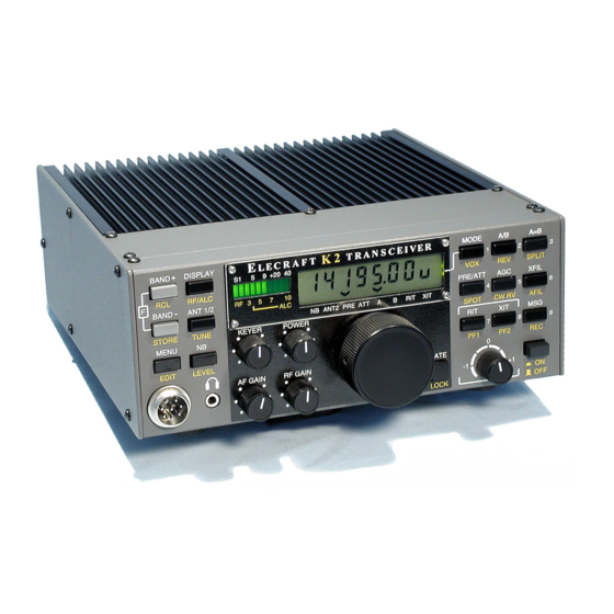
Summary of Contents for ELECRAFT K2/100
- Page 1 Appendix G, 100-W Stage and RS-232 I/O (K2/100) Rev H3, July 24, 2017 E740035...
-
Page 2: Table Of Contents
Using the K2/100 at High Power ................................ 57 Remote Control using the RS-232 Port ............................. 60 K2/100 Specifications ..................................65 Troubleshooting and Repair ................................66 Circuit Details ..................................... 70 Schematic Diagrams ..................................71 Parts Placement Drawings................................. 73 Elecraft manuals with color images may be downloaded from www.elecraft.com. -
Page 3: Introduction
RS-232 interface. Filter switching, T- source. Ordering information can be found on our web site, R sequencing, and other configuration is handled by the K2/100's main www.elecraft.com. You do not need to send your cores or wire to the microcontroller. winding service. -
Page 4: Customer Service Information
(We want to make sure everyone who is not disclosed to Elecraft at the time of original order, are not covered by succeeds!) this warranty. If the Elecraft product is being bought indirectly for a third party,... -
Page 5: Parts Inventory
Set the heat sink, shield, and painted panels aside until needed. Leave them wrapped to protect their finish. You should do a complete inventory (see below), which may take an hour or more. If anything is missing, contact Elecraft. Color codes and other markings are shown in parentheses. - Page 6 Picture Ref. Designator(s) Description Part # Cap., 180 pF ("181"), 5%, 50V disc, 0.2" LS; voltage may not be marked E530008 C67,C80,C81,C86 Cap., .0047 µF ("472"), 10%, 100V disc, 0.25" LS E530102 C2E,C83 Cap., 1000 pF ("1000"), 5%, 500V silver mica E530085 C2A,C6D Cap., 1200 pF ("6122"), 630V polypropylene...
- Page 7 Picture Ref. Designator(s) Description Part # D16,D17 Diode, 1N5711 E560004 Ground terminal, right angle PCB mount, 6-32 threaded E700012 FAN1 Fan, 12 V E980046 Connector, SO239 (Antenna) E620064 J3, P3 Connector, DC power, red housing (13.8 VDC input and mating conn., +) E620059 J3, P3 Connector, DC power, black housing (13.8 VDC input and mating conn., -)
- Page 8 Picture Ref. Designator(s) Description Part # Keying insert for ribbon cable connector MISC E700065 (Shown approx. 4x actual size; may include large break-away tab) MISC Connector, DB9M (serial I/O cable, K2 end) E620049 MISC Connector, DB9F (serial I/O cable, PC end) E620048 MISC Backshell for serial I/O cable...
- Page 9 Picture Ref. Designator(s) Description Part # Resistor, 0 ohms (jumper); see text Resistor, 470 ohms, 5%, 1W (YEL-VIO-BRN) E500075 R19,R20 Resistor, 1.6 ohms, 5%, 2W E500177 R21,R34,R35 Resistor, 10 ohms, 5%, 2W E500077 R38,R39 Resistor, 22 ohms, 5%, 3W E500128 Resistor, 300 ohms, 5%, 2W E500129 Resistor, 100 ohms, 5%, 3W...
- Page 10 Picture Ref. Designator(s) Description Part # HDWR Fuse holder housing, twist-lock (for external 20A fuse) E980047 HDWR Fuse holder contacts, #12 size E980048 HDWR Fuse holder spring, for 1.25" long fuse E980049 HDWR Fuse, 20A, Littlefuse #312020 or equivalent (1 spare) E980050 HDWR Jackscrew, 4-40, hex (for J8)
- Page 11 Picture Ref. Designator(s) Description Part # MISC Heat sink, KPA100, approx. 7.6" W x 6" L (19.23 x 15.2 cm) E100127 MISC PC board, KPA100 E100134 MISC Top cover trim panel, KPA100, painted (wrapped in paper) E100135 MISC Rear panel, KPA100, painted and silk-screened (wrapped in paper) E100136 MISC Shield, KPA100, approx.
- Page 12 Picture Ref. Designator(s) Description Part # MISC 1 ft. Hookup wire, #24, solid conductor, green ins. (for K2 Control board mod) E760008 MISC 1 ft. Stranded, Teflon-insulated wire, #22 gray (for T1) E760020 MISC 2 ft. Stranded, Teflon-insulated wire, #18 gray (for T2) E760021 MISC Cable tie, 3"...
-
Page 13: Assembly, Part I
Assembly, Part I With the bottom side of the board facing you (speaker cutout at the upper right), locate the position for resistor R28, along the back edge, far right. The label "R28" is just above of the resistor’s outline. Place the KPA100 PC board as shown in Figure 1, and identify the top side, which has most of the components. - Page 14 On the top side of the board, locate the component outline for .005- The leads on small capacitors are fragile. Do not pull on the ohm current-sensing resistor R7 (near the DC power connector, J3). Each leads or bend them excessively. of R7's pads has three holes.
- Page 15 The color bands on 1/4-watt 1% resistors can be difficult to read. Install and solder the RF chokes listed below. Limit soldering time Use a DMM (digital multimeter) to verify the values of all these resistors. on miniature chokes (2 to 3 seconds per lead). All chokes are on the top Tape them to a piece of paper with their values labeled.
- Page 16 Near the "ELECRAFT" label, you’ll find a short jumper location, Check the resistance across each RF choke using the lowest resistance scale of your DMM. This will ensure that the chokes were not identified by a ground symbol ( ). Use a saved 1N4007 diode lead to damaged during soldering.
- Page 17 Inspect the 11 relays closely to make sure that they’re seated flat Install the 0.2" lead spacing capacitors listed below on the top side against the PC board. If not, re-heat the corner pins one a time while of the board. Start with C11, which is along the front edge of the board pressing down on the relay.
- Page 18 Install the low-pass filter capacitors listed below. All are 500 V or Install the small capacitors listed below. (The first capacitor in the 1KV (1000 V) disc, with 0.2" lead spacing. These capacitors are located list, C50, is near trimmer C27). Lead spacing (LS) and voltage are on the left side of the board between the two rows of relays (K3-K12).
- Page 19 Install the low-profile 18.432 MHz crystal ("S184ECSL") at X1, Examine the placement of P1. If it is not flat against the board, re- near the speaker cutout. Make sure the crystal is seated flat against the heat the soldered pin while pressing down on the connector. board, then solder.
- Page 20 MOSFET transistors Q6 and Q7 (ZVN4424) have a modified Transistor Q3 (MJE182) will be installed on the bottom side of the TO-92 package that must be oriented as shown in Figure 5b. Some board, near the board cutout for power transistor Q2. Place the transistor ZVN4424's may be labeled on both sides, so you'll need to go by the over its outline, with the metal side of the package facing away from shape of the part: orient the larger flat side toward the flat side of the...
- Page 21 Mount R40 on the bottom of the PCB as shown in Figure 7. There is no outline on the board for this resistor. Study the traces carefully to be Before handling ICs, touch a metal surface. ICs damaged by sure you have it positioned correctly. Position the resistor against the electrostatic discharge can become intermittent, and the resulting board.
- Page 22 Install J8 and solder just one of the 9 pins. Adjust the position of J8 as you did for the other connectors, making sure the connector is flat In the following steps you'll be installing several connectors against the board. Then solder the remaining pins. at the back edge of the PC board (top side).
-
Page 23: Initial Tests
Visual Inspection Initial Tests Make the resistance measurements listed below, touching the Nearly all problems with kits are caused by poorly-soldered DMM's (+) and (-) leads to the indicated points. The (-) lead will go to component leads or incorrectly-installed components. You can locate ground in all cases except the first measurement (relay coils). - Page 24 This requires cutting one pin on the male connectors at each end. The pin to be cut, 8T (8-volt transmit), is not used by any Elecraft option. If you need 8T for any reason, skip the next three steps, as well as the last step on this page.
- Page 25 Cut pin 4 of P1 on the KPA100 board (see Figure 12). Locate the pre-assembled ribbon cable. Lay the cable flat as shown in Figure 13, with the black wire at the top and the connector holes facing up. Cut Pin 4 Black Wire Pin 1 Mark Pin 1 Mark...
- Page 26 1.06, a new 28-pin IC (16C72A or 16F872) should have been supplied with your KPA100 kit. Install it at this time, with pin 1 of the IC Turn on the K2; you should see ELECRAFT on the LCD, oriented toward the left side of the K2.
- Page 27 to check the K2 power supply voltage (E) and , then tap to bring up the K2's secondary D I S P L AY M E N U D I S P L AY current (i). If the voltage is lower than expected, or the current is over menu (SEC will be flashed).
-
Page 28: Assembly, Part Ii
Place L4 on top of the photo above, then hand fatigue. adjust the turns spacing until it is similar to that shown. Pre-wound toroids are available from an Elecraft-approved source; see page 3. - Page 29 Prepare the leads of these toroids as you did for L4. The enamel wire can be heat-stripped. Place a small amount of solder (a "blob") on the end of your soldering iron, then insert the clipped end of the wire into the hot solder. If the iron is hot enough, you should see the insulation bubble after 4 to 6 seconds.
- Page 30 Place each of the low-pass filter toroids on its photo and adjust the Prepare the leads of L16 and RFC1 as before. turns spacing so it is similar to that shown. Re-check turns counts and Install L16, located near relay K2. core colors.
- Page 31 Strip and tin the leads of T3. (Figure 20 shows the leads tinned.) Keep the red and green leads spaced slightly apart during stripping and tinning. Using a magnifying glass, examine the red/green lead pairs to make sure that the leads are not shorting together near the core. Install T3 vertically on the PC board as indicated by its outline (near the microcontroller, U1).
- Page 32 Install T4 vertically on the PC board as indicated by its outline near If masking tape (usually green in color) is present on the inside the small notch (back edge). Insert the red and green leads into their surface of the rear panel, you'll need to remove it. Use a ball-point pen to numbered holes as shown in Figure 23.
- Page 33 Solder Lug Fan W ires BLACK Figure 24...
- Page 34 Cut the two fan wires to a length of 2" (5 cm), measured from where Solder one end of the red wire to the center pin of the antenna they exit the fan's frame. Remove 1/4" (6.4 mm) of insulation from each connector (J2) as shown in Figure 24, Detail A2.
- Page 35 Solder the red fan wire to the pad labeled "FAN+" (near J6). Solder Place T1 at its indicated location, with the gap (bottom side) toward the black fan wire to the "FAN-" pad. the PC board. Contacts 1, 2, and 3 must be aligned with their PCB pads. Figure 25c shows all of T1's pads (1-5).
- Page 36 There are two sizes of Teflon wire (gray): #18 (larger) and #22 (smaller). The smaller size will be used at T1, and the larger at T2. Cut a 9" (23 cm) length of the #22 Teflon wire. Remove 1/4" (6 mm) of insulation from one end, then twist the strands together.
- Page 37 Locate the larger binocular coil form for use at T2. Note: T2 may Cut an 18" (46 cm) length of #18 Teflon wire (gray). Remove 1/4" vary in length from 1" to 1 1/8" (25 to 29 mm). The given pads can (6 mm) of insulation from one end, then twist and tin the strands.
- Page 38 Install the following resistors near T1. Note: Two sizes of 10-ohm Unwrap the heat sink and place it on a soft, clean surface to protect resistors are to be installed. The first to be installed, R9, is the smaller the finish. Orient it with the speaker hole at top left and fins facing down size, rated at 1/4 watt.
- Page 39 Using your DMM's lowest resistance scale, check for continuity (< 1 Over the rest of the board, trim any component leads that you may ohm) between one set screw and all of the others. have missed earlier, including connector leads. Use a ruler to make sure that all leads are trimmed to less than 1/8"...
- Page 40 Secure Q1 and Q2 to the pedestal temporarily using four 4-40 x 1/4" Check the position of C83 to ensure that no part of the body is higher than the circuit board end plate of T2. If it is higher than the edge (6 mm) pan head screws and four split lock washers.
- Page 41 Cut a 6" (15 cm) length of two-conductor speaker cable (small Separate the braid (shield) from the center conductor at both ends. gauge, with clear insulation). Split the conductors at both ends, then Clip off about half the strands of the braid close to the jacket, then twist remove 1/4"...
- Page 42 Figure 33...
- Page 43 The 12V and RF cables to the K2 use identical connectors. In the At this point you should have no unfilled component locations next section, a capacitor will be added to the RF board to prevent damage except C82, L15 and R12. If others are unfilled, make sure no steps were to components in the event that the cables are reversed.
- Page 44 Secure the rear panel to the heat sink using three 4-40 x 3/16" (4.8 Locate the two TO-126 thermal pads (rectangular, gray). mm) black pan head screws. Remove the adhesive backing, then attach them to the heat sink pedestal (adhesive side down) at the locations marked Q3 and Q4 in Adjust the locations of the thermal pads for Q1 and Q2, if necessary, Figure 36.
-
Page 45: Alignment And Installation
Alignment and Installation Slide the tongue on the right side of the red housing into the groove on the left side of the black housing. Make sure the housings are mated exactly as shown, with the black housing to the right and the "hoods" at You will need two power supplies to complete testing of the the front of the connectors facing up. - Page 46 5/16" (8 mm) of insulation, then solder the wire to a fuse terminal (c). amp power supply has its own fuse or circuit breaker. This will allow you to use the K2/100 transceiver with an unfused power supply or Pull the terminals back inside the holder halves, and install the battery if the need arises.
- Page 47 Q7 and Q8, on the bottom of the RF board. If any of the plastic hardware or the thermal pads appears to be melted or damaged, you should order the K2 PA Hardware Kit from Elecraft. Re-install the heat sink/lower panel and any new Q7/Q8 hardware as described in Part III of the basic K2 assembly instructions.
- Page 48 Receiver Tests Set the KPA100 upside down to the right of the K2 on a suitable platform, as you did earlier. Plug a pair of headphones into the K2's headphone jack. Turn on the Connect a low-current (3 amp minimum) power supply to the K2's K2 and adjust the AF GAIN control so that noise can be heard.
- Page 49 Power Calibration (R26 and R27) control for about 5 watts. Temporarily remove power from your K2/100 and set the FWD and Connect an external wattmeter between the KPA100 antenna jack REFL potentiometers on the KPA100 (R26 and R27) for about 43K ohms (J2) and the 50-ohm dummy load.
- Page 50 (barrel connector, RF-J3). Make sure your high-current power supply is turned off. Turn the K2 ON. After ELECRAFT is shown on the LCD, you should see the message NO PA PS. POWER range will be 0.1-15 W. Connect the high-current supply (20 A) to KPA100-J3.
- Page 51 Bias Current Adjustment Turn the high-current supply back on. Turn off and disconnect the low-current power supply. It should This is the most important KPA100 alignment step. If your not be used during the remaining tests. 20-amp power supply does not have accurate current measurement capability in the 0-1 amp range, you'll need a DC milliammeter to set Fan Test the bias current.
- Page 52 Test the KPA100 at your dummy load's rated power, up to 100 watts. Limit key-down time to a few seconds. Note: If you're using an antenna, and the SWR is too high for a given power level, the K2/100 Transmit Tests will automatically reduce power.
- Page 53 Before you go "live" in SSB mode, you should make sure that Each clip should be perpendicular to the edge of the shield, and you've properly aligned your K2/100 transceiver's filters for USB extending beyond the edge by about the amount shown. If necessary, and LSB transmit.
- Page 54 Figure 40...
- Page 55 Verify that the two standoffs at the front edge of the KPA100 board The two remaining solder lugs will be used to form a ground strap are 1/2" (12.7 mm) tall. The others should be 5/8" (16.9 mm). between the shield and rear panel as shown in Figure 39a. Attach one lug to the shield screw nearest the SO239 connector.
- Page 56 60. positions will be adjusted in later steps.) Read the entire section titled Using the K2/100 at High Power, Secure the KPA100 to the K2 only at the four locations identified as starting on page 57, before putting your K2/100 on the air.
-
Page 57: Using The K2/100 At High Power
RANT menu entry. supply voltage). If you turn the high-power supply back on, you'll see PA PS ON. The K2/100 will go in and out of bypass mode when the high- Ground current supply is turned on and off. - Page 58 E D I T AN T 1 / 2 The PA parameter has four possible settings: Puts the K2/100 into tune (key down) mode at no more than 20 T U N E watts. Can be overridden by holding together.
- Page 59 Other Important Operating Information Transmit Warning Messages If SWR is too high, you'll see HI REFL on the LCD. If current is too high, you'll see HI CUR. In both cases, power will be reduced as needed. PA HOT indicates an unsafe heat sink temperature; tap any switch to clear the message.
-
Page 60: Remote Control Using The Rs-232 Port
Remote Control using the RS-232 Port The trace between Q5-gate and U6 pin 25 must be cut as shown below. This trace is located on the top side of the Control board. Once Control Board Preparation you have located the trace, use a sharp tool such as an X-acto knife to make two small cuts near the location marked with an "X". - Page 61 RS-232 Interface Setup and Test Twist the strands of each wire together and tin them lightly with solder. Connect the KPA100 to the K2 Control board via the ribbon cable Locate the DB9F (female) and DB9M (male) connectors. Arrange (see page 26). Also connect the KPA100 speaker cable (J5) to the K2 RF them as shown in Figure 42 (male connector on the right, solder cups board.
-
Page 62: Computer Control
You can use your logging or control program to verify that basic Locate the connector housings (backshells) and associated hardware. operations such as band or mode change are working. (See Software Note: A single hinged backshell may be provided rather than a two-piece Configuration, following page.) backshell. - Page 63 K2. Check our web site additional On the desired port, set baud to 4800, and set device to information. Also available on the web is the Elecraft KIO2 XCVR1. Select F5 (Equipment Configuration). Set XCVR #1 Programmer's Reference, which you can consult when writing your own to KENWOOD1 Run NA.
- Page 64 RF Detect RF level feedback (DC), intended for use including Elecraft's K2REMOTE program. (For details on the TX, with an external automatic antenna tuner. RX, and KY commands, refer to the KIO2 Programmer's Reference.)
-
Page 65: K2/100 Specifications
K2/100 Specifications Key-down time At full power (100 W), All measurements were made using a 13.8 V, 20-amp power supply and 10 sec max. recommended 50-ohm load. Numeric values are typical; your results will be somewhat different. Specifications are subject to change without notice. (Note:... -
Page 66: Troubleshooting And Repair
Replacing the power transistors (Q1, Q2): If you need to replace the C), or that you have installed new KPA100 firmware without doing CAL RF power transistors, use only a matched set (request the Elecraft K2/100 tPA (see at left). Tap any switch to clear the message. After correcting PA Replacement Kit). - Page 67 Power output low: If power output is somewhat low across all bands, it may be because you used an inaccurate wattmeter during calibration of Miscellaneous R26/R27. Other possibilities include incorrect bias adjustment (R6), PA menu parameter missing: Make sure KPA100-U1 is not installed reversed or poorly-prepared leads on T4, or a T-R switch problem (check backwards, and has no bent pins.
- Page 68 Exxx status information: The Exxx parameter, which is one of the The status codes are: 1: PA is in QRP mode. 2: No power supply is PA menu entry settings, may be useful in troubleshooting. It can show up connected to the high-current DC jack. 4: SWR became very high during to 3 one-digit status codes, alone or in combination.
- Page 69 Table 4. KPA100 Transistor and IC DC Voltage Chart Band=40m, DC supply voltage 14.1 VDC; Power level 11w or greater; High Current PS connected and powered on. Important: The voltages shown were actual measurements made on a properly working KPA100. Variations of up to 10% of the value shown due to power supply voltage differences and component tolerances are to be expected.
-
Page 70: Circuit Details
In high-power (QRO) mode, Q10 and Q11 are turned on by the SCALE Circuit Details line from U1. This pulls RP1 pins 2 and 3 to ground, which, in combination with R24 and R25, divides the VFWD and VREFL voltages Sheet 1 by approximately 3.16 (square root of 10). -
Page 71: Schematic Diagrams
(Ext. Fuse) R7 .005 ohm s 1N5404 S PKR 2.7 ohms .047 .047 .047 12K2 2.7 ohms Elecraft Not on the PC board. S B530 LMC6482 W. Burdic k Rev. Date S ht. E. S wartz 9/21/10 1 of 2... - Page 72 Low-Pass Filters T D62083 S .M. S .M. or ULN2803 BIAS SET TES T POINT S .M. T P1 /OUT 0 /OUT 1 /OUT 2 /OUT 3 C3D C3F /OUT 4 /OUT 5 LPF IN LPF OUT /OUT 6 /OUT 7 VRFEN S CALE T P3...
-
Page 73: Parts Placement Drawings
Parts Placement Drawings (Top Side) KPA100 REV B 2002 ELECRAFT TD62083 16F872 (SOCKET) MAX1406 BIAS SET C30 C33 C34 100K 100K T1-4 T1-5 RFC4 C6G C6F RFC8 RFC7 RFC6 RFC9 RFC1 FAN- FAN+ Note: C82 is not used. The space shown for it should be empty. - Page 74 Parts Placment Drawing (Bottom Side)
Need help?
Do you have a question about the K2/100 and is the answer not in the manual?
Questions and answers