ELECRAFT K3S Assembly Manual
Hide thumbs
Also See for K3S:
- Kit assembly and instruction manual (91 pages) ,
- Owner's manual (90 pages) ,
- Programmer's reference manual (33 pages)

Related Manuals for ELECRAFT K3S


Summary of Contents for ELECRAFT K3S
- Page 1 LECRAFT ERFORMANCE 160 – 6 M ETER RANSCEIVER SSEMBLY ANUAL Revision B, July 16, 2015 Copyright © 2015, Elecraft, Inc. All Rights Reserved E740259...
-
Page 2: Table Of Contents
Installing the KANT3A input module or S-Meter Calibration (Optional) ........ 75 KAT3A antenna tuner ......... 48 Appendix A, Illustrated Parts List......A1 Installing the Right Side Panel ......49 Resistance Checks ..........52 Elecraft manuals with color images may be downloaded from www.elecraft.com. -
Page 3: Key To Symbols And Text Styles
Key to Symbols and Text Styles Identifies important information. Characters displayed on the LCD screen - 100 Tap switch function (labeled above a switch) D I S P Hold switch function (labeled below a switch; hold for 1/2 sec. to activate) AV E R AG E Typical menu entry MENU:Font... -
Page 4: Introduction
Repair / Alignment Service (We want to make sure everyone succeeds!) If necessary, you may return your Elecraft product to us for repair or alignment. (Note: We offer unlimited email and phone support to get your kit running, so please try that route first as we can usually help you find the problem quickly.) - Page 5 Elecraft products transferred by the purchaser to a third party, either by sale, gift or other method, who is not disclosed to Elecraft at the time of original order, are not covered by this warranty. If the Elecraft product is being bought indirectly for a third party, the third party's name and address must be provided to Elecraft at time of order to insure warranty coverage.
-
Page 6: Preventing Electrostatic Discharge Damage
Preventing Electrostatic Discharge Damage There is no climate or work location where the components of your K3 are safe from Electrostatic Discharge (ESD) unless you take specific steps to prevent such damage. Many of the components in your K3 can be damaged by static discharges of only a few volts: far too little for you to notice. -
Page 7: Preparing For Assembly
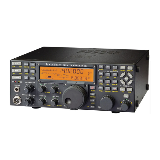
The main chassis is literally built up around the RF circuit board, which fills the entire bottom of the unit of the chassis assembly. Panels are mounted around the RF board using Elecraft’s 2D fasteners. These fasteners allow individual removal of any one panel, if needed, to gain access to the inside of the radio for servicing. Very few cables or wires are used in the kit. - Page 8 Figure 1. Typical Assembled K3 /10 (Less Top Cover and Chassis Stiffener Bar).
-
Page 9: Tools And Test Equipment Required
Tools and Test Equipment Required #0 and #1 size Phillips screwdrivers. To avoid damaging screws and nuts, do not use a power screwdriver. Use the screwdriver that best fits the screw in each step. 2. Soft cloth or other surface to lay cabinet panels on to avoid scratching. A clean static-dissipating mat is ideal (see below). -
Page 10: Unpacking And Inventory
Unpacking and Inventory CAUTION Do not handle the circuit boards without anti-static protection! Doing so may damage sensitive components. See Preventing Electrostatic Discharge Damage on page 6 for important information before proceeding. Before starting construction, do a complete inventory, comparing the parts in your kit with the parts list in Appendix A, to familiarize yourself with all of the parts and to ensure the kit is complete. -
Page 11: Screws
Screws A number of different types and sizes of screws and washers are used in the assembly. It is very important that you use the screw specified in each location or your finished K3 may not fit together properly. In some places, using the wrong size screw may damage components. -
Page 12: Assembly
Assembly IMPORTANT ASSEMBLY INFORMATION 1. Screws and other Fasteners: A variety of screws and fasteners are used to assemble your K3 Stainless Steel Hardware: Exterior screws are stainless steel to avoid corrosion in harsh environments. Where the stainless steels screws would be impossible to separate from similar screws in a bag of parts, they are supplied in a separate bag marked E850714 SS Hardware Kit. -
Page 13: Front Panel And Dsp
Front Panel and DSP Front Panel and DSP Description The Front Panel is a large plug-in module that provides the K3 user interface (LCD, switches, shaft encoders, potentiometers, and LEDs) as well as the microcontroller (MCU) and parameter storage (EEPROM and FLASH). - Page 14 On the front side of the board, mount four standoffs as shown in Figure 7. IMPORTANT! 1. Place the split lock washers between the standoff and board as shown in the figure. This is important to establish the correct spacing between the board and the front panel.
- Page 15 If you see a label on the face of the LCD, there is a thin plastic film covering the LCD front REMOVE FILM glass(see Figure 8). Pull up on the edge of the paper label marked by an arrow and the label and film will lift off together.
- Page 16 Locate a 2-56 5/32” (4.0 mm) fillister head screw found in the small envelope marked E700311 Bezel Screws. Thread the screw through each of the four threaded holes at the corners of the opening in the front panel for the LCD to ensure they are clear of paint (see Figure 10). Lubricate the screw if the fit is tight. A drop of water on the threads will usually work well and it is easier to wipe away excess water than oil.
- Page 17 Two identical encoder assemblies are provided for VFO A and VFO B. Select one encoder and place a 1/2” (13mm) inside tooth lock washer over the threaded shaft as shown in Figure 12. This will be the VFO A encoder. Figure 12.
- Page 18 Place the VFO B encoder in the opening near the end of the front panel board so the nut rests against the inside of the front panel and the encoder pins mate with J34. The connectors may not mate fully, leaving a very small area of the pins showing.
- Page 19 CAUTION! In the next step, use only the screws indicated. Using the wrong screw may break the LCD cover glass and ruin the display. Locate the envelope marked E850710, K3 Bezel Screws. Use only these screws to mount the bezel as shown in Figure 16, with the shorter fillister head screws used at the four corners of the display.
- Page 20 Place the larger of a pair of concentric knobs over the RF/SQL - SUB control as follows (See Figure 18): CAUTION! Do not over-tighten the set screws in the knobs in the following steps or you may crack the knobs! Use only enough torque to hold the knobs in place. Turn both shafts fully clockwise Place the larger knob over the shafts.
- Page 21 CAUTION! You may damage the encoders while installing the knobs in the next step unless you align the flats in the knobs with the flats on the shafts as described below. Press small knobs on the four controls under the left end of the LCD: SHIFT/LOW HI/WIDTH SPEED/MIC...
-
Page 22: Mounting The Sub Receiver Auxiliary Dsp Board
Mount the last knob on the VFO B encoder shaft to the right (under the pushbutton switches) as shown in Figure 21. Before tightening both set screws, adjust the position of the knob against the felt washer to produce the desired amount of drag for smooth movement without the knob turning too freely. Figure 21. - Page 23 Mount the three 7/16” (11mm) male/female standoffs on the component side of the main DSP board as shown in Figure 23 using 4-40 nuts and #4 split lock washers. Be sure that: The standoffs are on the component side of the board as shown. No lock washer is used between the standoff and the board.
-
Page 24: Installing The Kdvr3 Digital Voice Recorder Option
Locate resistor R3 on the front panel board (mounted on the front panel). If R3 is positioned above the board on its leads as shown in Figure 25, push it over to one side of the outline as shown. Be sure you don’t push it so far its leads might touch the solder pads for other components on the board. -
Page 25: Mounting The Dsp Board Assembly On The Front Panel
Mounting the DSP Board Assembly on the Front Panel Locate the main DSP board and install the nylon standoff near J51 as shown below. Be sure you place it in the correct hole near the edge of the board. The standoff is also shown in Figure 26. CAUTION: To avoid damaging a circuit trace very close to the metal ring around the screw hole, position the lock washer under the screw so the split faces away from the trace. - Page 26 Squeeze the boards together while ensuring the pins are mating with the connectors until the DSP board is resting against the three standoffs on the back of the front panel board that you installed earlier. The two connectors will not mate completely. About 1/4” (6.4mm) of the pins may be visible when the DSP board is positioned against the standoffs.
-
Page 27: Rf Board And Chassis
Screw the knurled nut onto the threaded shaft of the PHONES jack where it exits the front panel (see Figure 30). Screw it only finger tight. Do not use pliers. Figure 30. Phones Jack Hardware. Set the front panel assembly aside in a safe place while you assemble the RF board and chassis. RF Board and Chassis RF Board Description The RF board is the heart of the K3... - Page 28 Figure 31. RF Board Partially Assembled.
-
Page 29: Rf Board And Chassis Assembly
RF Board and Chassis Assembly CAUTION There are components on both sides of the circuit boards. When handling them, be careful not to damage components on either side by placing the board on top of tools or other objects, or bumping or crushing the components while mounting parts or installing the boards Remove the RF board from its anti-static packaging. - Page 30 Install the two KBPF3A standoffs shown in Figure 35. Even if you didn’t purchase the KBPF3A general coverage option, the standoffs and hardware are included in the K3 kit to make installing the option easier at some future date. Note that these standoffs have only one lock washer between each standoff and the RF board Figure 35.
- Page 31 Enter the FREQ OFFSET shown on each filter. The optional 8-pole filters have no offset marked on them. Enter a zero in the FREQ OFFSET column for those filters. For the 5-pole filters, note that the frequency offset may be negative, indicated by a minus sign (single dash) ahead of the number. Table 1.
- Page 32 Locate the K3 top cover. On the inside is a label with places to record the bandwidth (BW), and frequency offset (FRQ) of each filter. Copy the information from Table 1 and place a check mark by Main (for main receiver) on the label.
- Page 33 Installing the Front Panel Shield Mount a 2D fastener on each ear of the front panel shield, and then mount the shield on the RF board as shown in Figure 39. Be sure the 2D fasteners are oriented with the widest part between the two holes and the edge toward the outside as shown.
- Page 34 Installing the KXV3B Interface Module The KXV3B Interface provides a separate receive antenna input and output, inputs and outputs for use with an external transverter, and a buffered i.f. output. Also included is a high-gain, low-noise preamplifier that provides extra sensitivity on the 12 through 6 meter bands. Complete details for using the KXV3B are included in the Owner’s manual.
-
Page 35: Installing Antenna Connectors On The Rear Panel
Peel the backing from the self-adhesive serial number label and attach it to the outside surface of the back panel as shown in Figure 43. You may wait until the assembly is finished before attaching the serial number, but at this point you can lay the panel flat on the work surface to easily position the label square within the outline. Figure 43. - Page 36 Nut and internal tooth lock washer that fits the BNC connector. (They may be supplied threaded onto the connector. If so, remove them.) One 4-40 3/8” (9.5 mm) black pan head screw. One #4 internal tooth lock washer. One 4-40 nut. The highly scratch-resistant powder coating on the rear panel may interfere with the fit of the BNC connector through the hole.
- Page 37 CAUTION Later you will apply power to do preliminary testing and calibration before the KRX3A sub receiver is installed. Failure to insulate the TMP connector as described above may result in short circuits and extensive damage to your K3 if it touches a component, solder pad or other exposed circuit points.
- Page 38 Position the rear panel on the edge of the RF board opposite the front panel shield you installed earlier. The BNC connectors to the KXV3B module fit through an the opening in the rear panel (see Figure 49). The lower lip of the rear panel goes under the 2D fasteners on the RF board. Secure the rear panel with the ground screw as shown.
-
Page 39: Mount Front Panel Assembly On The Chassis
Mount Front Panel Assembly on the Chassis Turn the chassis upside down and position the front panel assembly so the pins of P30 and P35 on the bottom of the RF board just begin to engage the connectors on the lower edge of the front panel assembly (see Figure 63). - Page 40 Secure the front panel assembly at the bottom lip to the 2D fasteners at the forward edge of the RF board with two 4-40 3/16” (4.8 mm) black pan head screws (SS). Turn the K3 right side up and secure the front panel assembly at the top lip to the 2D fasteners at each end of the front panel shield and at the threaded PEM nut at the center with three 4-40 3/16”...
-
Page 41: Installing The Kio3B Interface
Plug the TMP coaxial connector into the KXV3B module and route the cable through the notch in the RF board as shown in Figure 55. Figure 55. Connecting Coax Cable to KXV3B Module. Installing the KIO3B Interface All rear-panel audio and digital/computer I/O is routed through the KIO3B. The KIO3B is made up of three PC boards: Main, Audio I/O and Digital I/O. - Page 42 Figure 57. Mounting Audio I/O Daughter Board on KIO3B. Install the KIO3B Main board with the Audio I/O daughter board attached into the K3 as shown in Figure 58. The KIO3B main board plugs into J76 on the RF board. The KXV3B coaxial TMP cable fits between the KXV3B and KIO3B boards.
-
Page 43: Installing Battery Bt1
The DB9 multi-pin connector on the KIO3B Digital I/O daughter board may have jackscrew nuts installed on the connector. (Jackscrew nuts are shown in Figure 60). If so, remove them. They will be reinstalled shortly. Install the KIO3B Digital I/O daughter board as shown in Figure 59. Be careful to support the KIO3B main board as shown while pressing the daughter board in place. - Page 44 CAUTION Once the battery is installed, take care not to set the K3 on a metal tool or other conductive surface that could short the battery and damage circuit traces. If you wish, you can delay installation of the battery until the K3 is complete.
- Page 45 Attach the handle to the left side cover using the hardware shown in Figure 63 at each end. The ribbed side of the handle faces away from the panel. Tighten the screws enough to compress the lock washers, but do not tighten the screws so much that you deform the handle end cover.
- Page 46 If you do not have the optional K144XV two-meter module, install three 6-32, 1/4” (6.4 mm) screws in the larger holes in the side panel shown in Figure 65. Use a #6 nut and split ring lock washer on the inside to secure each screw.
- Page 47 Turn the K3 over and plug the KXV3B cable into P86 on the RF board as shown in Figure 66. Figure 66. Routing the KXV3B Cable to P86.
-
Page 48: Installing The Kant3A Input Module Or Kat3A Antenna Tuner
Installing the KANT3A input module or KAT3A antenna tuner The basic K3 /10 includes a KANT3A antenna input module. If you’ve ordered a KAT3A antenna tuner, the KANT3A is not required and will not be supplied with the kit. In either case, the module plugs into the RF board at the back-right corner. -
Page 49: Installing The Right Side Panel
Connect the wires from the SO239 connector(s) to the KANT3A or KAT3A board as shown in Figure 69. Use needle-nose pliers to grip the terminals on the wire ends and carefully insert the connectors straight into the holes in the board. They may be very difficult to insert unless they are perfectly aligned. While inserting the plugs, support the board with your fingers to avoid putting stress on the connector at the bottom. - Page 50 Figure 70. Installing Side Panel Feet. Position the right side panel against the K3 to verify how it will fit against the RF board. When it is oriented correctly, the three holes along the bottom edge will line up with the holes in the 2D fasteners on the RF board and two holes in the side panel will be aligned with the tabs on voltage regulators U12 and U13.
- Page 51 Mount the KANT3A or KAT3A board to the standoff on the side panel with a 4-40 1/4” (6.4mm) zinc pan head screw and a #4 split lock washer under the screw head as shown in Figure 73. Do not place a washer between the board and the standoff.
-
Page 52: Resistance Checks
Resistance Checks The following resistance checks confirm that the main power busses aren’t shorted to ground. If any of the values measured are lower than specified, inspect the unit carefully for loose hardware that is caught between components on the boards or for improperly mated connectors. Use your digital multimeter (DMM) to measure the resistance across the red and black 12VDC IN connectors on the rear panel. -
Page 53: Initial Power On Check
Initial Power On Check The following check confirms that the power supply and power control circuits are working properly. Be sure your K3 passes the resistance tests above before proceeding. CAUTION! If you see or smell smoke when applying power, turn the K3 off and remove the power cable immediately, then locate the source. - Page 54 Mount the TCXO module on the KREF3 board as shown in Figure 76. Be certain the leads go into the corner holes in the socket and the black dot is oriented toward connector J6 as shown. If you have a 1ppm high-stability module, the dot may be light brown and not as close to the corner.
- Page 55 CAUTION In the following step it is easy to drop screws and lock washers into the K3 . If this happens, you must find and retrieve the hardware. Failing to do so may cause short circuits and damage your K3 when power is applied.
-
Page 56: Installing The Ksyn3A Synthesizer
Installing the KSYN3A Synthesizer The KSYN3A module is a high-performance, wide-range synthesizer covering 8 to 46 MHz. It is based on a high-performance phased-lock loop IC that uses direct-digital synthesis for fine tuning. This IC has exceptionally low timing jitter, resulting in very low phase noise. The output signal is locked to the K3's 49.380- MHz reference to within a fraction of a Hz. - Page 57 Install the KSYN3 board on the back side of the front panel shield as shown in Figure 80. The screws and lock washers are supplied in a separate envelope marked KSYN3A. Figure 80. Installing the KSYN3 Board. Locate the three TMP cables. They are about 1/8” (3 mm) diameter coaxial cables with connectors at each end as shown in Figure 81.
- Page 58 Install the three TMP cables between connectors on the KREF3 board, the main RF board and the KSYN3 board as follows. Handle the connectors by the finger-grip area shown in Figure 81, especially if you unplug a connector. Do not pull on the coaxial cable to unplug a connector! When mating the connectors, be sure the plugs are fully inserted as shown in Figure 81.
-
Page 59: Loudspeaker, Top Cover And Kpa3A Shield
Loudspeaker, Top Cover and KPA3A Shield The built-in loudspeaker is mounted on the top cover. A grill cloth covering the sound holes keeps dust and debris from falling into the speaker cone. The loudspeaker is equipped with a magnetic shield to avoid unwanted interaction with nearby circuits. - Page 60 Place a fiber washer on each screw so it rests on the grill cloth. Position the loudspeaker on the four screws so they pass through the holes in the flanges. Orient the speaker so the wire exits toward the rear (the side nearest the stiffener). Place a #4 internal tooth lock washer on each screw.
-
Page 61: Kpa3A Shield
KPA3A Shield If you are not planning to install the KPA3A module at this time, skip this section and go directly to Installing the KNB3 Noise Blanker on page 61. Only the KPA3A shield is installed at this time to avoid rework later. You will be directed to finish installing the KPA3A module after initial testing and calibration of your K3 The KPA3A shield is part of the optional KPA3A 100-watt amplifier module. -
Page 62: Installing The Chassis Stiffener
Figure 88. Installing Noise Blanker Standoff. Plug the noise blanker board into J77 and attach it to the standoff using the hardware shown in Figure 89. Figure 89. Installing the Noise Blanker Board. Installing the Chassis Stiffener Remove the stiffener bar from the top cover and install it on the chassis as shown in Figure 90. The hardware required to attach it to the shield are in the KPA3A Option kit. -
Page 63: Bottom Cover
Figure 90. Installing the Chassis Stiffener Bar. Bottom Cover Bottom Cover Description The bottom cover is divided into two parts, the rear and forward sections. The rear section is slightly thicker than the forward section to act more efficiently as a heat sink for the LPA transistors. The bottom covers attach to standoffs as well as the 2D fasteners on the bottom of the RF Board. - Page 64 Figure 91. Installing Standoffs on RF Board. Identify the bottom cover forward section by test fitting it on the bottom of the K3. The forward section is the thinner panel with a notch along one edge (see Figure 92). One side of the cover is fully painted. That is the outside. The other side has areas of bare metal left to ensure good electrical contact with the other cabinet parts.
- Page 65 Figure 92. Installing Tilt Stand. Locate the rear bottom cover section. This cover has eight rectangular slots cut in it. Like the front section, bare metal is exposed in some areas on the inside surface. The bare metal ensures good electrical contact with the other cabinet parts and good thermal contact with the heat sinks for Q4 and Q5 on the KLPA3A circuit board.
-
Page 66: Kbpf3A General Coverage Receive Option
KBPF3A General Coverage Receive Option If you have the KBPF3A General Coverage Receive option kit, install the board as follows. Otherwise skip this section and go directly to Power Amplifier Jumper Block on page 66. KBPF3A Description The KBPF3A extends the receive coverage outside of the Ham bands over the range of 100 kHz to 30 MHz and from 48 MHz through 54 MHz. -
Page 67: Battery Bt1
Figure 95. Installing the PA Jumper Block. Battery BT1 Battery BT1 Installation Procedure If you did not install the real time clock battery earlier, do so now. Remove the left side panel as shown in Figure 96. Figure 96. Removing the Left Side Panel. Insert the CR2032 cell into battery holder BT1 as shown in Figure 61 on page 44 . -
Page 68: Aux Rf Cable
The blank panel has a BNC connector hole marked ANT3. This is for the optional K144XV module. If you do not have the K144XV, press a BNC Hole Cover into the opening in the panel with the small, smooth end of the cover on the side of the panel that has the ANT3 label. - Page 69 Locate the two thermal insulators and clear the screw holes. They are already cut. If material is still covering the holes, push a small tool through the hole to remove the unwanted material. Remove the protective backing from each insulator and press the adhesive side against a low-power amplifier transistor with the hole in the insulator aligned with the screw hole in the transistor as shown in Figure 98.
- Page 70 Install the rear bottom cover section as follows (see Figure 99): Be sure the KXV3B cable going to P86 is not on top of one of the LPA transistors where it would become trapped between the bottom cover and the transistor. Position the cover so the holes near the center line up with the transistors on the LPA board.
-
Page 71: Top Cover
Top Cover Even if you have the KPA3A 100-watt module to install, install the top cover and speaker at this time for initial testing and calibration of the basic 10-watt K3 configuration. Connect the speaker cable to P25 of the KIO3B board as shown in Figure 100. If you have the KPA3A shield installed, route the speaker wire under the stiffener bar. - Page 72 If you have the KPA3A shield installed, place three 4-40 3/16” (4.8 mm) black flat head screws (SS) through the holes across the middle of the cover to secure it to the stiffening bar. If you have not installed the KPA3A shield, the stiffening bar is still attached to the top cover where you mounted it to measure the speaker grill cloth for trimming.
-
Page 73: Test And Calibration
Test and Calibration It’s time to apply power! In the following tests and procedures you will check out and calibrate essential functions of your basic K3 . You must complete these procedures before operating your K3 at low power or before installing a KPA3A 100-watt power amplifier option. -
Page 74: Filter Setup
Filter Setup Turn to the Crystal Filter Installation and Setup section of your Owner’s Manual and perform the following procedures. If you have installed standard Elecraft 5-pole filter(s) you will need the FREQ OFFSET data you recorded earlier on page 31. -
Page 75: Option Modules
The S-meter calibration is normally quite accurate with the default settings provided. If you have an accurate 50- ohm, 50-microvolt signal generator (such as the Elecraft XG1 or XG2) you can calibrate the S-meter yourself. Refer to Calibration Procedures, S-Meter in your Owner’s manual. -
Page 76: Appendix A Illustrated Parts List
KPA100 KAT3 Automatic Antenna Tuner are supplied in separate boxes with their own parts lists. They are not shown here. As you assemble your K3s, you will be directed to install those options or prepare your K3 for them to be installed after initial testing and checkout at the proper points in the assembly procedure. - Page 77 E850323 KREF3 TCXO Module Bag ELECRAFT ILLUSTRATION DESCRIPTION PART NO. KREF3 TCXO Module, 49.380 MHz, ±5 ppm stability E660033 This module is not supplied if you purchased the optional ±1 ppm module shown below. Tie Wrap, KREF3 TCXO. Module E980145...
- Page 78 All user calibrations and adjustments are done in firmware using the front panel menus. These are described at the appropriate points in the assembly procedures and in the Owner’s Manual. ELECRAFT ILLUSTRATION DESCRIPTION PART NO.
- Page 79 ELECRAFT ILLUSTRATION DESCRIPTION PART NO. Mixer PCB Assembly E850257 ESD Sensitive. KNB3 Noise Blanker PCB Assembly E850280 ESD Sensitive. KREF3 PCB Assembly E850254 ESD Sensitive. KSYN3A Assembly E850638 ESD Sensitive A- 4...
- Page 80 ELECRAFT ILLUSTRATION DESCRIPTION PART NO. KIO3B Main PCB Assembly E850645 ESD Sensitive. KIO3B Audio I/O PCB Assembly E850647 ESD Sensitive. KIO3B Digital I/O PCB Assembly E850646 ESD Sensitive. KXV3B PCB Assembly E850644 ESD Sensitive. A- 5...
- Page 81 Miscellaneous Components Packed in separate bags and envelopes as follows: E850305 K3 Knobs for Front Panel (bag) ELECRAFT ILLUSTRATION DESCRIPTION PART NO. Knob, VFO B Tuning E980090 Knob, RIT/XIT E980089 Knob, Concentric Shaft, Large E980092 Knob, Concentric Shaft, Small E980091...
- Page 82 E850697 K3 Knob and Band for VFO A (bag) ELECRAFT ILLUSTRATION DESCRIPTION PART NO. Knob, VFO A Tuning E980093 Finger Grip, Main VFO Tuning Knob E980285 E850698 K3 Front Panel Bezels and Serial Number Label (bag) ELECRAFT ILLUSTRATION DESCRIPTION PART NO.
- Page 83 In addition there is a small bag marked K3 Hardware Spares Bag. It contains a collection of small parts that are easily lost. Normally you will not need any of the parts it contains to build your kit. ELECRAFT ILLUSTRATION DESCRIPTION PART NO.
- Page 84 ELECRAFT ILLUSTRATION DESCRIPTION PART NO. Typical Standoffs Standoff, 4-40, 1/4” (6.4 mm) long E700026 (May be round or hexagonal) Standoff, 4-40, 3/8” (9.5 mm) long E700153 Standoff, 4-40, 1/2” (13 mm) long E700061 Typical Pan Head Screws Screw, 4-40, 1/4” (6.4 mm) Zinc, Pan...
- Page 85 E850713 KXV3B Hardware ELECRAFT ILLUSTRATION DESCRIPTION PART NO. Lock Washer, #4, Internal Tooth E700010 4-40 Nut, Hex E700011 Screw, 4-40, 1/2" (13 mm) Black Pan E700177 Head E850714 Stainless Steel (SS) Hardware (in K3 RF Misc Bag) ELECRAFT ILLUSTRATION DESCRIPTION PART NO.
- Page 86 E850717 K144XV Side Panel Hardware Envelope (in K3 RF Misc Bag) ELECRAFT ILLUSTRATION DESCRIPTION PART NO. Screw, 6-32, 1/4” (6.4 mm) Black Flat E700185 Head Lock Washer, #6, Internal Tooth E700095 Nut, 6-32 E700069 E850680 KSYN3A Envelope (in K3 RF Misc Bag)
- Page 87 E850709 Front Panel Hardware Bag ELECRAFT ILLUSTRATION DESCRIPTION PART NO. Felt Washer E700033 Knurled Nut (Phones Jack) E700138 Standoff, 2/56, 5/16” (7.9 mm) long E700122 Typical Standoffs Standoff, 4-40, 5/16” (7.9 mm) long E700121 Standoff, 4-40, 5/8” (15.9 mm) long E700003 Standoff, Nylon, 5/8”...
- Page 88 Do not mix these screws up with other parts in the Front Panel Hardware bag. Confusing them with other screws nearly the same length may destroy your front panel board. They are packaged separately for your convenience. You will be instructed when to use each screw in the assembly procedure. ELECRAFT ILLUSTRATION DESCRIPTION PART NO.
- Page 89 E850695 K3 RF BSF Assembly (in box) RF Board E850651 ESD Sensitive PA Jumper Block Assembly (pre-installed on E850325 RF board) A- 14...
- Page 90 E850701 K3 Chassis Set (in box) ELECRAFT ILLUSTRATION DESCRIPTION PART NO. Front Panel E100557SS Top Cover E100212 Rear Panel E100214SS Front Panel Shield E100216 Chassis Stiffener E100222 KIO3B Digital I/O Panel E100558SS In bag marked E850702 KXV3B Panel E850704 Loudspeaker with attached...
- Page 91 E850312 Side Panels ELECRAFT ILLUSTRATION DESCRIPTION PART NO. Left Side Panel E100210 Right Side Panel E100211 E850313 Bottom Covers (Wrapped) ELECRAFT ILLUSTRATION DESCRIPTION PART NO. Bottom Cover A E100213 Bottom Cover B E100221 E850718 Carrying Handle Bag ELECRAFT ILLUSTRATION DESCRIPTION PART NO.
- Page 92 Cables in Separate Bags ELECRAFT ILLUSTRATION DESCRIPTION PART NO. Power Cable APP and Ring Terminals KPCA-F RJ-45 to DE-9S E980297 USB A-B Cable E850720 A- 17...
Need help?
Do you have a question about the K3S and is the answer not in the manual?
Questions and answers