ELECRAFT K2 Owner's Manual
Hide thumbs
Also See for K2:
- Owner's manual (161 pages) ,
- Instruction manual (16 pages) ,
- Troubleshooting (3 pages)
Advertisement
Quick Links
Advertisement
Chapters

Related Manuals for ELECRAFT K2


Summary of Contents for ELECRAFT K2
- Page 1 T r a n s c e i v e r Owner’s Manual Revision C, April 19, 2000 Copyright 1999-2000 Elecraft, All Rights Reserved Elecraft • www.elecraft.com P.O. Box 69 • Aptos, CA 95001-0069 (831) 662-8345 • Fax: (831) 662-0830...
-
Page 2: Table Of Contents
LECRAFT Table of Contents INTRODUCTION....................................3 SPECIFICATIONS ....................................5 PREPARATION FOR ASSEMBLY..............................7 CONTROL BOARD................................... 13 FRONT PANEL BOARD................................... 21 RF BOARD......................................32 FINAL ASSEMBLY.................................... 75 OPERATION....................................... 78 MODIFICATIONS..................................... 100 THEORY OF OPERATION................................101 INTERNAL OPTIONS..................................108 PARTS LIST.....................................APPENDIX A SCHEMATIC.....................................APPENDIX B BLOCK DIAGRAM..................................APPENDIX C PHOTOGRAPHS..................................APPENDIX D... -
Page 3: Elecraft
1. Introduction The Elecraft K2 is a high-performance, synthesized, CW/SSB A unique feature of the K2 is that it provides its own built-in test transceiver that covers all HF bands. It is a true dual-purpose equipment, including a digital voltmeter, ammeter, wattmeter, and transceiver, combining the operating features you’d expect in a... - Page 4 Please use e-mail, rather than call, materials. You must send the unit at your expense to Elecraft, but we when possible since this gives us a written record of the details of will pay return shipping.
-
Page 5: Specifications
PLL synthesizer w/single VCO covering 6.7-24 MHz in 9 bands; fine steps via DAC-tuned reference The K2 can receive well outside the ham bands, but this extended range is not specified or guaranteed Current varies with band, supply voltage, configuration, and load See Frequency Calibration Techniques (Operation section, under Advanced impedance. - Page 6 LECRAFT Transmitter Receiver Preamp On Preamp Off Power output <0.5 W to >10 W (typ.); Sensitivity (MDS) -135 dBm -130 dBm power setting resolution 0.1 W, -order intercept 0 to +7.5 accuracy 10% @ 5 W -order intercept Duty cycle 5 W, 100%;...
-
Page 7: Preparation For Assembly
As shown in Figure 3-2, there are three printed circuit boards This concept extends to the chassis (Figure 3-1). Any chassis (PCBs) in the basic K2 kit: the Front Panel board, Control Board, element can be removed during assembly or troubleshooting. (Also and RF board. - Page 8 LECRAFT Board-to-board Connectors The circuit boards in the K2 are interconnected using board-to-board connectors, which eliminates nearly all hand wiring. Gold-plated contacts are used on these connectors for reliability and corrosion resistance. Figure 3-3 shows a side view of the PC boards and board-to-board connectors. As can be seen in the drawing, the Front Panel board has a connector J1 which mates with right-angle connector P1 on the RF board.
-
Page 9: Unpacking And Inventory
For example, in step 3 you’ll put the modules Identifying Capacitors together for the first time, allowing you to try out the K2’s built-in frequency counter. The counter will then be used in step 4 to align Small-value fixed capacitors are usually marked with one, two, or and test the receiver and synthesizer on 40 meters. - Page 10 BLACK would have a value of 27 µH. Blue x 1M Violet Tools Gray White The following specialized tools are supplied with the K2: Silver x .01 Gold x 0.1 .050" (1.3 mm) Allen Wrench, short handle 5/64" (2 mm)
- Page 11 Magnifying glass Bottom-Mounted Components Conductive wrist strap A number of components in the K2 are mounted on the bottom of Assembly Notes the PC boards to improve component spacing or for electrical reasons. Component outline symbols are provided on both sides of each board, so it will always be clear which side a particular component goes on.
- Page 12 PC board very difficult to repair. Invest in a PC board vice with a heavy base if possible. This The printed circuit boards used in the K2 have circuitry on both makes parts removal easier because it frees up both hands.
-
Page 13: Control Board
LECRAFT 4. Control Board The control board is the "brain" of the K2. It monitors all signals during receive and transmit, and handles display and control functions via the front panel board. The microprocessor, analog There are five sizes of 4-40 machine screws provided with and digital control circuits, automatic gain control (AGC), and audio the kit. - Page 14 LECRAFT Solder all of the resistors, then trim the leads as close as Assembly possible to the solder joints. All of the components to be installed are on the top (component Note: Whenever you see an instruction to solder one or side) of the control board.
- Page 15 LECRAFT Install the diodes listed below, beginning with D1, which is in Install and solder the electrolytic capacitors listed below, the upper left-hand corner of the PC board. (Refer to the parts list which are polarized. Be sure that the (+) lead is installed in the hole if necessary to identify the different types of diodes.) If a diode has marked with a "+"...
- Page 16 LECRAFT Install Q12 near the upper left-hand corner of the PC board. Align the large flat side of Q12 with its PC board outline as in Figure 4-2. The body of the transistor should be about 1/8" (3 mm) above the board; don’t force it down too far or you may break the leads.
- Page 17 LECRAFT Install a 40-pin IC socket at U6. (The microprocessor will be Install the 10-pin, dual-row connector, P4. It is located to the inserted into the socket in a later step.) Orient the notched end of left of P5. It must be seated flat on the board before soldering. the socket to the left as shown on the PC board outline.
- Page 18 LECRAFT Top side of PC Board In the following steps, the three multi-pin connectors along the bottom edge of the board (P1, P2 and P3) will be installed. These connectors must be positioned and soldered carefully. Incorrect alignment of these connectors may cause instability or intermittent operation, and it is very difficult to remove them once they are soldered.
- Page 19 LECRAFT Bend two of U2’s corner pins out slightly on the bottom of the board to hold the IC firmly in place, flat against the top of the Before handling any IC, touch an unpainted, board. Find pin 1 and verify that its pad is either round or oval. grounded metal surface or put on a conductive wrist-strap.
- Page 20 (KAF2). This option should be installed or even infinite. This is typical when using a DMM (digital only after the basic K2 kit has been completed and tested. multimeter). If you use an analog meter you may find that some or all resistance measurements are too low.
-
Page 21: Front Panel Board
Locate the front panel PC board, which is just a bit larger than four legs of each switch are centered in their holes, then gently the control board. It is labeled "K2 FP" on the top side, in the push each switch until it is resting flush against the switch-spacing lower right-hand corner. - Page 22 (R13 and a few other components in its vicinity are Install PN2222A transistors at Q1 and Q2, near the middle of part of the SSB adapter option, and are not included in the basic K2 the board, and solder. These transistors must be mounted so the lead kit.
- Page 23 3/16" (4.8 mm) long pan-head machine screws. will interfere with final front panel assembly. Also, any misalignment will be visible from the front of the K2. Locate the bargraph LED, DS2. The bargraph has a beveled corner or edge that indicates pin 1. Install DS2 as shown by its PC board outline, just to the left of the LCD.
- Page 24 LECRAFT Install another 3/16" (4.8 mm) diameter x 1/4" (6.4 mm) long Install the audio-taper potentiometer, R3, in the lower left- round standoff on the top of the PC board, on the left side of the hand corner. (The PCB is labeled "5 K" under R3, even though a large square hole in the middle of the board.
- Page 25 LECRAFT Install rectangular gray key caps on S1 and S3 so the key caps are parallel to the long axis of the PC board (Figure 5-8). The caps are installed simply by pressing them onto the switch plungers. Gray keycaps diffuser Square Keycap spacers (2)
- Page 26 LECRAFT Examine the backlight assembly closely to ensure that it is The LCD must be seated flat against the diffuser as shown in parallel to the front panel board and seated as far down on the the edge view (Figure 5-11). If the LCD does not appear to be board as it will go (exactly 1/8"...
- Page 27 LECRAFT Uninstalled Components Resistance Checks Check off each of the components in the list below, verifying Set all potentiometers to their mid-points (approx.). that they are not yet installed. Perform the resistance checks listed below. U1 is on the back of the board.
- Page 28 LECRAFT Front Panel Final Assembly Locate the green plastic bargraph filter and two pieces of double-backed tape. These items will be found in a small bag. Locate the front panel chassis piece. Place it on a soft cloth to protect the finish and labeling. Some holes in the front panel were masked on the inside Caution: The adhesive on the double-backed tape is surface during painting.
- Page 29 LECRAFT Remove the brown paper backing from the other side of each Turn the front panel face up. piece of tape, then turn the filter/tape assembly adhesive-side down. Position the clear plastic LCD bezel over the LCD and Carefully center the green plastic filter over the inside of the bargraph holes, then secure it with four 2-56 screws (stainless steel) bargraph LED hole (Figure 5-14).
- Page 30 LECRAFT Remove the insulation from four 1.5" (38 mm) lengths of Insert the front panel PC board assembly into the front panel. green hookup wire. The pushbutton switch caps on both sides of the LCD should protrude slightly as shown in the side view, Figure 5-17a. Install the bare wires on the bottom of the front panel PC board, using the four pads below the large rectangular hole (Figure Note: the board/panel assembly will not be rigidly held in place...
- Page 31 LECRAFT Attach the encoder to the inside of the front panel using the Locate the 1" (25 mm) diameter by 1/16" (1.6 mm) thick felt nut and flat washer only. Figure 5-18 shows the side view (a) and washer. Place the washer over the encoder’s finishing nut (Figure 5- front view (b) with encoder properly installed.
-
Page 32: Rf Board
For example, "front-left" means the corner closest to you on the left. Part II: Synthesizer and receiver components are installed and tested. By the end of Part II you’ll have the K2 receiving on 40 meters. Part III. Transmitter components and all remaining filter... - Page 33 LECRAFT Take a moment to familiarize yourself with the RF board using Turn the board over and install 2-D fasteners at five locations Figure 6-1 to identify the major sections. If you flip the board over on the bottom of the RF board as shown in Figure 6-3. Secure each you’ll see that there are a few components on the bottom of the fastener from the top side of the board with two chassis screws and board, primarily in the transmitter section.
- Page 34 LECRAFT Make sure that the 2-D fasteners on the edges line up with the Install R1 and R2 (220 ohms, RED-RED-BRN), near the back edge of the PC board and do not hang over. If they hang over or do left corner of the board.
- Page 35 LECRAFT Install the key jack, J1, at the back-left corner of the board. Before soldering, make sure that the jack is aligned with its PC In the steps that follow you’ll install the connectors that board outline. mate with the control and front panel boards. These connectors must be installed properly to ensure reliable mechanical connection.
- Page 36 LECRAFT Position 20-pin male right-angle connector P1 on the bottom of the board (Figure 6-5), but do not solder P1 yet. Review Figure Before handling U1, touch an unpainted, grounded 3-3 for correct placement. The short ends of the bent pins are metal surface or put on a conductive wrist-strap.
- Page 37 LECRAFT When working with the side panels in the following steps, place a soft cloth on your work surface to protect the paint. Locate the two side panels. Remove any masking tape from Holes offset the panels using the same technique described in the Front Panel away from section, taking care not to scratch the outer surfaces.
- Page 38 Locate the tilt stand, which can be found in the MISCELLANEOUS component bag. It has three parts: two oval Since the K2 chassis is made up of a number of individual feet and a tilt bail (Figure 6-9). Note: the screws that will be used to panels and fasteners, you may need to loosen the fasteners and hold the tilt bail in place are not the black anodized type.
- Page 39 LECRAFT Turn the RF board/side panel assembly upside down. Check for any untrimmed component leads on the bottom of the board. Position the bottom cover as shown in Figure 6-10, then secure it using six chassis screws. (The heat sink and rear feet will not be installed until Part III when the transmitter is assembled.) With the entire assembly still upside down or resting on one side panel, plug the front panel assembly into the RF board (Figure...
- Page 40 LECRAFT Plug the control board assembly into the RF board, with the Once you have tried the control board extraction technique component side of the control board facing backwards. (Refer to described above, plug the control board back in for the tests that the photos in Appendix D.) All three connectors on the control follow.
- Page 41 Set the controls on the front panel as follows: Turn on the K2 using S1. After about 10 seconds, you should see the default K2 frequency display for 40 meters: 7 1 0 0 . 0 0 c . AF GAIN: midway (12 o’clock)
- Page 42 LECRAFT Turn the K2 off and wait for a few seconds, then turn it back Tap the button three times. You should hear relays P R E / A T T N on. The display should now show E L E C R A F T for about two switch each time.
- Page 43 1/2 second to activate the E D I T You should not leave it connected inside the K2 during normal EDIT function. (Remember the TAP/HOLD rule: when you HOLD operation, since it may cause shorts or unwanted noise pickup.
- Page 44 M E N U Trim the leads of the 10 pF axial-lead capacitor down to 1/4" returns you to the normal K2 display. (6 mm). Solder one end to the center conductor of the coax cable. In the following section you’ll activate the C A L F C T R (frequency counter) function.
- Page 45 The connector can only be plugged in one way. tapping the button. The display will show B A N D + Turn on the K2 and tap to bring up the menu, then M E N U S T P 0 . 6 0 scroll to the C A L menu entry.
- Page 46 LECRAFT S-Meter Alignment Enter the menu and verify that G R P H (LED bargraph mode) is set to D O T , not to B A R or O F F . The bargraph S-meter zero and sensitivity will be coarsely set in the following steps.
- Page 47 LECRAFT Note: Remember to complete each line of resistors before Assembly, Part II proceeding to the next line (i.e., install R9, then R16, then R10). In this section you’ll install the components for the synthesizer __ R9, 100 k (BRN-BLK-YEL) ⇒ __ R16, 10 k (BRN-BLK-ORG) and receiver circuits.
- Page 48 MV209 and type 1SV149. (1SV149 diodes are labeled "V149" and may have a center lead that has been cut flush with the body of the device.) The K2 will not function correctly if the Install Q21 (2N5109), which is located near U1 in the middle varactor diode types are interchanged.
- Page 49 __ C153, 68 (68) __ C155, .01 (103) __ C172, .01 (103) "ELECRAFT" label at the middle of the board. Make sure that Z6 is lined up with its component outline and is flush with the board __ C177, .022 (223)
- Page 50 LECRAFT Locate the crystals used on the RF board: 12.096 MHz (2), Sort the black and dark gray toroidal cores into three groups to 4.915 MHz for BFO (2) and 4.915 MHz for crystal filters (7). The avoid mis-identifying them in later steps. You should have seven BFO and filter crystals are bagged separately.
- Page 51 LECRAFT Verify that the turns of RFC14 are not bunched together. They should be evenly-spaced and occupy about 85% of the core’s T5 is a toroidal transformer, with two numbered windings. circumference. If the turns are all bunched together, RFC14’s These numbers are printed next to each pad on the PC board.
- Page 52 LECRAFT Install T5 as shown by its component outline in the T7 is a toroidal transformer wound on a 3/8" (9.5 mm) synthesizer area of the board. Figure 6-17 shows how the 1–2 and diameter ferrite core (dark gray, FT37-43). T7’s orientation and windings will appear similar to Figure 6-18.
- Page 53 LECRAFT Transformer T6 is mounted vertically, near the middle of the When winding is completed, clip and untwist the ends of the board. It uses a different winding technique where the wires for the red/green pairs so that the leads of the transformer look like those two windings are twisted together before winding ("bi-filar").
- Page 54 LECRAFT Review Figure 4-2 before installing Q2 in the next step. (continued) Q2 is a ZVN4424A transistor, which has a slightly modified TO-92 __ C133, 0.1 (104) (bend body of cap toward PC board before soldering) package. It is flat on both sides, and the labeling may be on the smaller flat side.
- Page 55 LECRAFT L33 is located on the bottom of the board, near the front panel connector, P1. It will be wound on a T44-8 (yellow/red) toroid core. Previously, a standard solenoidal RF choke was used at . L33 still has a rectangular component outline on the board. Locate the T44-8 core for L33 (yellow/red, 0.44"...
- Page 56 LECRAFT Visual Inspection It is very important to re-assemble the chassis as described below before attempting the alignment steps in the next section. If Examine the bottom (solder side) of the RF board carefully for you don’t put the chassis together, some alignment steps will not be unsoldered pins, solder bridges, or cold solder joints.
- Page 57 MHz range. It may or may not be stable at this time (i.e., the end near the 4 MHz crystal on the K2 control board. Find the frequency may be changing). If the reading is 0000 kHz or is oscillator signal on the receiver.
- Page 58 7300 ______ Disconnect the internal frequency counter probe and remove 30 m 10000 ______ 10150 ______ it completely from the K2. 20 m 14000 ______ 15000 ______ Select 80 meters, and set the VFO for about 4000 kHz. 17 m...
- Page 59 RF board near the crystal filter. If you didn't calibrate the K2's internal frequency counter using Using the menu, select C A L F C T R . The counter should show an external counter, it may not be reading accurately.
- Page 60 The K2 uses a variable-bandwidth crystal filter, allowing the operator to set up as many as four filter bandwidths for each Allow the K2 to stabilize for at least 5 minutes at room operating mode. Each of these filter configurations requires an temperature (approx.
- Page 61 Slowly tune the VFO to locate the weak internally-generated This will allow you to align and test the K2 on all bands. signal near 7000 kHz. If you can't hear the signal at all, you may have a receiver problem.
- Page 62 LECRAFT __ C221, 39 (39) __ C220, 220 (221) __ C214, 68 (68) Install the following 1/4-watt resistors, starting with R46 __ C213, 33 (33) __ C212, 150 (151) __ C203, 47 (47) which is just to the left of I/O controller U1. __ C199, 220 (221) __ C200, 150 (151) __ C202, 120 (121)
- Page 63 LECRAFT Ferrite-bead assemblies Z1 and Z2 will be installed vertically Install the following components on the bottom of the board, near transformer T3 as indicated by their component outlines. To working from left to right. make these assemblies, string two ferrite beads onto a 1" (25 mm) __ R63, 220 (RED-RED-BRN) length of bare hookup wire (or discarded component leads) as shown in Figure 6-24.
- Page 64 LECRAFT TO-220 package transistors Q6, 7, and 8 look identical, but It is very important to wind and install toroidal Q6 is different. Locate the two 2SC1969’s (labeled "C1969"), Q7 transformers T1 through T4 exactly as described in the following and Q8, and set them to one side.
- Page 65 LECRAFT T2 is wound on the same core type as T1. Its windings must be Separate T3’s leads as shown in Figure 6-27. Strip and tin the spaced as shown in Figure 6-26, with the 3-4 winding occupying leads, being careful not to let the red/green wire pairs short together.
- Page 66 LECRAFT Locate the "binocular" (2-hole) ferrite core for T4. Wind 2 Before installing T4, verify that the screws holding the 2-D turns of green insulated hookup wire (5", 13 cm) through the core fastener beneath it are tightened, and that #4 internal-tooth lock as shown in Figure 6-28.
- Page 67 LECRAFT Place Q7 on the bottom of the board so that the leads are inserted into the PC board as indicated by Q7’s component outline. The mounting screw and hardware should appear as shown in Figure PA transistors Q7 and Q8 (2SC1969) must be installed on 6-31.
- Page 68 Do not remove the option bypass jumpers (W1, W2, etc.), Visual Inspection even if you're planning to install the option components. The K2 must be aligned and tested before the jumpers are removed and Examine the bottom (solder side) of the RF board carefully for option modules installed.
- Page 69 PA transistor hardware as needed. Turn the K2 up on its left side. This will keep the PA transistor screws from slipping out during the following steps. Remove the 4-40 nuts and #4 lock washers from the mounting screws for Q7 and Q8, but do not pull the screws out.
- Page 70 LECRAFT Keeping the K2 on its left side, slip the heat sink over the Secure Q7 and Q8 on the bottom of the heat sink using 4-40 rear-panel connectors and into position (Figure 6-33). Figure 6-34 nuts and #4 lock washers. Do not over-tighten the nuts, as this may...
- Page 71 Tap any button to turn the SPOT tone off. S P O T Set the POWER control fully counter-clockwise (minimum power output). Turn on the K2. You should see E L E C R A F T on the LCD, followed by the frequency display.
- Page 72 Enter tune mode again and adjust L2 for maximum output. Tap any button to exit. The K2 transmitter is most efficient at 10 watts. If you plan to operate exclusively at 5 watts or less, see Modifications for ways to improve low- power efficiency.
- Page 73 Make sure the bottom cover is securely attached. Adjust L3 and L4 for maximum signal strength. Allow the K2 to stabilize for at least 5 minutes at room temperature (approx. 20-25° C). Since some inductors are shared between two bands, you Connect the frequency counter cable to the VCO test must always align the remaining bands in the order indicated.
- Page 74 LECRAFT Transmitter Alignment Since some inductors are shared between two bands, you If you did the receiver alignment, above, you may find that little or must always align the remaining bands in the order indicated. no transmit adjustment is required on most bands. Always use this procedure if you re-align the filters later.
-
Page 75: Final Assembly
LECRAFT 7. Final Assembly Place the top cover upside down as shown in Figure 7-1, with Place the speaker on the top cover in the position shown in the rear panel facing away from you. The illustration shows how Figure 7-1. Secure it with four 3/8" (9.5 mm) screws, #4 fibre the speaker, 2-conductor cable, external speaker jack and other washers (black), #4 lock washers, and 4-40 nuts (Figure 7-2). - Page 76 LECRAFT Install the external speaker jack in the hole labeled "EXT SPKR" on the rear panel. Orient the jack as shown in Figure 7-1 and Figure 7-4, with the "AF" tab nearest the inside of the top Ground cover. (Caution: Mis-identification of the three tabs could result in an AF output to ground short.) A 24"...
- Page 77 S1. The connector is keyed and can only be plugged in one way. Figure 7-6 Even if you have purchased some K2 options, you should not assemble and install them yet. The option manuals assume that you are familiar with basic K2 operation.
-
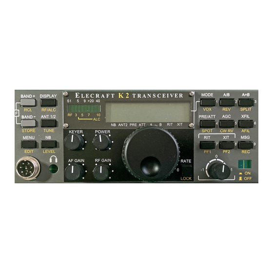
Page 78: Operation
RF 3 BAND ANT 1/2 PRE/ATT XFIL NB ANT2 PRE ATT STORE TUNE SPOT KEYER POWER CW RV AFIL MENU EDIT LEVEL AF GAIN RF GAIN RATE LOCK NUMERIC RIT/XIT KEYPAD (0) OFFSET POWER MICROPHONE ON/OFF JACK K2 FRONT PANEL... - Page 79 ANTENNA TUNER XVTR ANTENNA 12VDC RCV. ANT. 50Ω LECRAFT SER. NO. KEYER PADDLE, EXT. KEYER, OR HANDKEY 12V BATTERY OR MAIN ANTENNA SEPARATE RECEIVE POWER SUPLY (DO NOT USE IF ANTENNA (PART OF ATU IS INSTALLED) 160M/RXANT. OPTION) K2 REAR PANEL...
- Page 80 (see Calibration Functions), which will protect the power supply as well as the K2. You'll see H I C U R on the LCD if the A number of mounting holes are provided on the back panel of the programmed limit is reached.
-
Page 81: Controls And Display
When you turn this control, power output will be displayed in watts, Annunciators: The LCD provides eight Chevron-shaped e.g. P 5 . 0 . The range is 0.1 to 15 W for the basic K2, and 1 to annunciators, or status indicators: 100 W if you have the KPA100 amplifier installed. -
Page 82: Switch Functions
LECRAFT Switch Functions turn on preamp or attenuator P R E / A T T CW audio spot signal on/off S P O T Each pushbutton switch as two primary functions, indicated by the turn on RIT (annunciator flashes in high range) R I T upper and lower labels. -
Page 83: Using The Menu
For example, K2. If a parameter appears as "- - " in the menu, the associated you might see: L C D D A Y , indicating that the LCD is in "day"... - Page 84 A board). short test cable is provided for connecting the counter input to any of several internal K2 signals during alignment. To Linearize the VFO: Transmit Current Limit (CAL CUR) 1.
- Page 85 CW normal to CW reverse. Whenever you switch modes or Filter Bandwidth Display filters, the K2 will first record your new settings, if they have been changed. The initial C A L F I L display shows the present filter bandwidth and the operating mode, e.g.
- Page 86 Table 8-1 shows the recommended filer settings for a CW-only knob to select the value shown in the table. Typically you'll be K2. If you already have the SSB adapter installed, use the SSB able to get to within +/- 20 Hz of the target frequency.
- Page 87 Attenuator: If necessary, an additional 10 dB of attenuation can be Sideband Inversion: The K2 inverts the sideband on 15 meters switched in by turning on the attenuator. This is more effective than and above due to the frequency mixing scheme used (that is, the using the RF GAIN control in the case of strong-signal overload.
- Page 88 Day/Night Selection: If you're operating outdoors, use the menu The basic K2 kit covers the 80 through 10 meter bands. If you have to select L C D D A Y , which turns off the LCD backlight and puts the 160 m/RXANT option installed, 160 meters will also be the bargraph into high-brightness mode.
- Page 89 8400 kHz--which is typically band memories, respectively. outside the range of the synthesizer--the K2 will switch to 40 meters and setup the VFOs as they last were on this band. Store and Recall: Ten memories are provided, numbered 0 through 9.
-
Page 90: Power Control
LECRAFT Power Control VFO Selection Turn the POWER control to set the power output directly in To select the A or B VFO, tap . To set the unused VFO equal in A / B watts (e.g., P 5 . 0 ). The range of the control is 0.1 to 15 watts in frequency to the current VFO, tap . - Page 91 Once you have completely stopped frequency will be restored a minimum of 1/2 second later. tuning the VFO for at least 30 seconds, the K2 will then save your current operating frequency in EEPROM. As long as you stay on a particular frequency, no further updates will be done.
- Page 92 S P O T GROUND optional low-noise analog audio filter DO T DASH This section explains how to get the most out of the K2's CW KEYLINE features. H ANDKEY, COMPUTER, OR EXTERNAL 1N5817, 1N4148, etc.
- Page 93 LECRAFT Basic CW Setup The SPOT Switch Mode Selection: To place the rig in CW mode, tap the switch can be used to zero-in on received signals or to test M O D E S P O T your sidetone pitch quickly, without having to key the transmitter or switch until the mode indicator changes to C.
- Page 94 HOLD rather than TAP the numbered button (i.e., use # directly to the K2's key jack. Set I N P to P D L n or P D L r . ). Chaining is useful during contests. For example, you might set up message 5 as "QSL 73"...
-
Page 95: Ssb Operation
SSB adapter alignment. S S B C is used to set the be fed into the mic jack from your TU (terminal unit), and the K2’s speech compression level, from 1 - 1 to 4 - 1 . The SSB adapter audio output routed back to the TU from either the headphone jack manual explains how to optimize these parameters. -
Page 96: Advanced Operating Features
10 of your favorite scan ranges around for instant recall by using the memories. Once you've mastered the basics of operating the K2, you may When a station is found, the receiver will stay on that frequency wish to explore some of the more specialized features and for about 25 seconds or until the signal fades or disappears. - Page 97 18 mA. (Each segment uses only 6 mA in N I T E mode.) Note: Voltage/current display mode can be used to verify the effect of each setting. All of these settings are stored in EEPROM so they will be in effect whenever you turn the K2 on.
- Page 98 Scanning, earlier in this section. You can calibrate C22 using a signal generator, ham transmitter, or strong AM carrier such as WWV at 10 MHz. The K2’s receiver is To program , enter the menu and scroll to P F 1 or...
- Page 99 If you have the host I/O adapter installed (model KIO2), you’ll be the I/O controller's firmware revision. able to use a computer to control the K2. You can also read the current operating frequency and other parameters. Refer to the host...
-
Page 100: Modifications
However, this requires that the transmitter driver and PA AF). This signal could be used to drive an external audio stages be biased much closer to class A than they would be if the K2 filter/amplifier, RTTY terminal unit, etc. You'll need to supply were a CW-only rig. -
Page 101: Theory Of Operation
(An alternative is up-conversion followed directly by a product detector and audio filter. While The K2’s custom enclosure is also modular. It is fabricated in six pieces, this results in minimal parts count, it was not considered since the resulting with a unique 2-D fastener used at each joint and also for PCB support. - Page 102 4915.0 4915.5 The signals you tune in on the K2's receiver are "shaped" by the crystal filter, which passes only a narrow range of frequencies. The pitch of these signals is determined by the BFO (beat-frequency oscillator). Figure 10-1 shows an example of how these signals are related.
- Page 103 8 annunciators which indicate the settings of various controls. switching is handled by co-processors. There is only one co-processor in the basic K2, the I/O Controller (IOC). Some option modules, such as the SSB A 10-segment LED bargraph, DS2, is used to display received and adapter, have their own co-processors.
- Page 104 Offset) are multiplexed onto a single A-to-D input of the MCU, the "VPOTS" communication from MCU to the rest of the K2 is done via serial interfaces: line, so their position can be read. Firmware hysteresis is used for these...
- Page 105 U4 is a low-dropout 8 V regulator, which is stable with a K2 input DC The RF board is the largest of the three K2 boards, and serves as a structural voltage as low as 8.2 V. Since all signal-generating and signal monitoring element that the chassis and the other boards attach to.
- Page 106 Also shown on sheet 1 is the DC input circuitry (bottom right-hand corner), voltage is controlled by the microprocessor, providing BFO amplitude which is designed to protect the K2 and its power supply from almost any control. PIN diode D36 provides additional reduction in low-level signal conceivable mis-connection or short.
- Page 107 LECRAFT Sheet 3: Filters and I/O Controller The latching relays are wired with a single common drive line so that when one relay needs to be turned on or off, the others are pulled in the opposite The band-pass and low-pass filters are switched with latching relays to direction.
-
Page 108: Internal Options
It is intended with its own top cover/heat sink that replaces the K2's original top cover. If to match unbalanced antennas, but an external balun can be used with you have the internal battery or low-power internal antenna tuner, you can balanced feedlines. - Page 109 Appendix A K2 Control Board Parts List PICTURE Designators Value Description C2, C12, C20, C34 .001 Monolithic Cap, "102" C24, C36 .0027 Monolithic Cap, "272" C10, C11 C17, C18, C23, C3, C35, C37, C39, C40, C41, C42, C5, C9 Monolithic Cap, "103"...
- Page 110 Appendix A K2 Control Board Parts List PICTURE Designators Value Description D1, D2 1N4148 Silicon switching diode, small glass body 1N5817 Shottky diode, black body MISC 40 pin socket socket for MCU 6P male, RA Right Angle 6 pin connector...
- Page 111 Appendix A K2 Control Board Parts List PICTURE Designators Value Description 470,5R ISO "10A3-471G" SIP resistor pack, 10 pins; ALT: "770103471" 3.9K,5R ISO "770103392" SIP resistor pack, 10 pins; ALT: "10A3392G" 5.1K,5R ISO "770103512" Sip resistor pack, 10 pins; ALT: "10A3512G"...
- Page 112 Appendix A K2 Control Board Parts List PICTURE Designators Value Description 5.068Mhz Crystal, HC49 (may be standard or low-profile) 4.000MHz Crystal, HC49 (standard) Page 4 Control...
- Page 113 Appendix A K2 Front Panel Board Parts List PICTURE Designators Value Description C1, C3 .047 Monolithic, "473" C2, C9 Monolithic, "103" D2, D3 LCD Backlight Assy LED Backlights mounted in Diffuser D4, D5, D6 1N5817 (BLACK) VIM-838-DP 4-character, 7-Segment multiplexed LCD 10LED array Hi-eff.
- Page 114 Appendix A K2 Front Panel Board Parts List PICTURE Designators Value Description Misc Keycap, rect, black Black keycaps for Push Buttons ( BLACK) Misc Keycap, rect, gray Band up/down keycap; S1, S3 (GRAY) Misc Keycap, square, black Rate / Lock Keycap; S7, (BLACK, Square)
- Page 115 Appendix A K2 Front Panel Board Parts List PICTURE Designators Value Description S1, S2, S3, S4, S5, S6, S7, S8, S9, S10, S11, S12, S13, S14, S15, S16 switch, push button Front Panel push button switches Misc 40 pin socket...
-
Page 116: C181,
Appendix A K2 RF Board Parts List PICTURE Designators Value Description C1, C2, C9, C17, C26, C27, C37, C38, C39, C49, C57, C64, C77, C79, C80, C81, C82, C89, C100, C140, C167, C195, C204, C207, C208, C216, C223 .001 Monolithic Cap, "102"... -
Page 117: C144,
Appendix A K2 RF Board Parts List PICTURE Designators Value Description C221 NPO, "39" C20, C24, C73, C203 NPO, "47" C31, C35, C122 NPO, "56" C153, C104, C214 NPO, "68" C71, ,C174, C210 NPO, "82" C197, C222, C144, C5, C7 NPO, "101"... - Page 118 Appendix A K2 RF Board Parts List PICTURE Designators Value Description C44, C46, C32, C34 var,5-30pF ceramic trimmer (see below to tell from 50 pF) C21, C23 var,8-50pF ceramic trimmer (red mark or bagged separately) 1N5711 glass body D1, D2, D3, D4, D5, D6, D7, D36 1N4007...
- Page 119 Appendix A K2 RF Board Parts List PICTURE Designators Value Description 6p,female socket 6 x 1 female socket Antenna connector SJ-373 Keyer Jack, Threaded, Stereo, Vertical orientation Stereo+iso sw. Headphone jack. Horizontal Orientation TOKO, 15/17m BPF, 10/12m BPF. Small adjustment L10, L11, L12, L13 Variable Ind, 1µh "T1050"...
- Page 120 Appendix A K2 RF Board Parts List PICTURE Designators Value Description 10µH , Shielded solenoidal, shielded, DELEVAN (BLACK) Toroid (YELLOW/RED), 39 µH, see text (BFO) T44-8 Toroid (BLACK); 12/10m LPF(.32µH, .26µH); L21, L22, L23, L24 T44-10 17/15mLPF(.45µH) Toroid (RED); 80m LPF(2.50µH); 20/30m L16, L17, L18, L19, L20, L25, L26 T44-2 LPF(.58µH, .44µH, .37µH);...
- Page 121 Appendix A K2 RF Board Parts List PICTURE Designators Value Description Binocular core 2:3:1:1, Balun Core; Square, Two Holes Z1, Z2 Ferrite Bead 2 (GRAY) ferrite beads ea. on bare wire (see text) 20 x 1 ,male, RA 20 pin male, right angle. To Front Panel, J1 2p,male 2 pin male.
- Page 122 Appendix A K2 RF Board Parts List PICTURE Designators Value Description Q10, Q12, Q17, Q20, Q23 2N7000 TO-92 Q18, Q19, Q24 J310 TO-92 Q11, Q13, Q16 PN2222A TO-92 ZVN4424A Slightly Thinner TO-92 Style 100, POT - Trimmer PA Bias Adjustment R115 0.05 ohm...
-
Page 123: C145,
Appendix A K2 RF Board Parts List PICTURE Designators Value Description R91, R93, R100 (TAN) R10, R38, R39 (TAN) R79, R81 1.8K (TAN) R5, R24, R25, R34, R44, R62, R66, R73, R95, R96 2.7K (TAN) 4.7K (TAN) R111 5.6K (TAN) - Page 124 Appendix A K2 RF Board Parts List PICTURE Designators Value Description 78L05 5-volt reg. (100mA) MC145170P2 (or P1) 16 pin DIP, PLL W1, W2, W3, W5, W6 1" bare wire Use Component Leads X1, X2 12.096MHz X3, X4 4.9152MHz Crystal "4.91 - S" BFO Xtals; Series mode, matched, HC49 4.9152MHz Crystal;...
- Page 125 Appendix A K2 RF Board Parts List PICTURE Designators Value Description MISC Keycap; TAC-BLK Power Switch Keycap; rectangular MISC 28 pin socket, 0.3" DIP Socket for U1 heatsink TO5 Flush Crown heatsink; for Q22 standoff, 0.125"H x 1/4" D, phenolic; RAF #1122-4-PH...
- Page 126 Appendix A K2 Misc. Bag Parts List PICTURE Designators Value Description #4 int. tooth lockwasher 2-56,screw , 1/8", STAINLESS fillister head, STAINLESS 2-56 x 1/8”,slotted, for LCD bezel 2-D Fastener Chassis fasteners 4-40 nut, Steel-ZN 4-40 screw, 3/8”, black pan-head Phillips screw, black oxide steel (incl. spares) 4-40 screw, 3/16", black...
- Page 127 Appendix A K2 Misc. Bag Parts List PICTURE Designators Value Description SPK-J1 2 pin female conn. Housing 0.1” spacing w/locking ramp, int. speaker plug ACC-P1 2.1mm male conn. Mates with DC power jack ACC-P2 stereo 1/8” phone plug Plug for hand key/keyer/paddle/computer input...
- Page 128 Appendix A K2 Freq, Voltage and RF Probe Assy Parts List PICTURE Designators Value Description FCP-C1 10pf cap Axial Leads (like a resistor), for freq. counter probe .01 µF cap RFP-C1 Monolithic capacitor, for optional RF probe RFP-D1 1N34A germanium diode...
- Page 129 RF board parts Bag, Control Parts Control board parts Bag, Misc. Parts Hardware and Misc. parts K1, K2, K3, K4, K5, K6, K7, K8, K9, K10, K11, K12, K13, K14, K15, K16, K17 Latching Relay, 5V In plastic tube; 10-pin DIP...
- Page 130 Knob, 1.6" diam Main Tuning Knob, weighted, 6mm shaft KN2, KN3, KN4, KN5, KN6 Knob, 0.5" diam Small Control Knobs, 6mm shaft Docs Alert Sheet Docs Errata sheet Docs Packing List Docs Cover Letter Page 2...
-
Page 131: Special Symbols
B B B B P P P P F F F F L L L L P P P P F F F F V V V V C C C C O O O O 160m 160m-K1 K2, K3 Transistors K13, K14 K3, K4 K14, K15... - Page 132 M M M M i i i i c c c c C C C C o o o o n n n n f f f f i i i i g g g g ../MIC RD 5K (audio taper) K2 Front Panel Board Elecraft These components are supplied with SSB adapter.
- Page 133 Rev. Date Sht. W. Burdick E. Swartz 4/12/00 1 of 1 NOTE 1: R18 and R19 are 0 ohms (jumpers) in this version of the K2. Appendix B The jumpers must be removed if the Audio Filter option is installed.
- Page 134 K K K K 2 2 2 2 R R R R F F F F B B B B o o o o a a a a r r r r d d d d Elecraft W. Burdick Rev.
-
Page 135: C172,
1N4007 100K C155 Elecraft K K K K 2 2 2 2 R R R R F F F F B B B B o o o o a a a a r r r r d d d d B B B B F F F F O O O O B B B B u u u u f f f f f f f f e e e e r r r r / / / / A A A A t t t t t t t t e e e e n n n n u u u u a a a a t t t t o o o o r r r r * Remove C167 when SSB Adapter is installed. - Page 136 R R R R F F F F B B B B o o o o a a a a r r r r d d d d Elecraft L L L L P P P P F F F F...
- Page 137 CCW = MIN BIAS /CLASS AB Elecraft K K K K 2 2 2 2 R R R R F F F F B B B B o o o o a a a a r r r r d d d d Rev.
-
Page 138: Block Diagram
BAND- POWER LOW-PASS PASS DRIVER FILTERS FILTERS (10W) 4.915MHz ATTEN. POST- CRYSTAL NOISE MIXER I.F. AMP FILTERS MIXER BLANKER PREAMP XMIT BAL. BUFFER MIXER MOD. PROD. DETECTOR MCU AND SUPPORT 6 - 24MHz SYNTH. CIRCUITS 4.915MHz AF AMP Shaft Encoder DISPLAY AND CONTROLS Common... -
Page 139: Troubleshooting
Check values of R16 and R15 on the front panel When referring to components on the various K2 boards in the table, we will Check continuity from LCD driver (U1) to sometimes use a shorthand form such as “RF-U11,” which means U11 on the LCD. - Page 140 Disconnect the battery from (025) the K2 and measure its voltage; if the battery If the supply voltage and antenna impedance voltage quickly rises back to 11 or 12V, the are correct, the driver or PA transistors may K2 may be loading the battery down.
- Page 141 If +5V is too low (< 4.5V) go to 052 operating frequency operating the K2; otherwise the VFO cannot If +8V is too low (< 7.5V) go to 053 appears to be entirely be tuned properly and the synthesizer may...
- Page 142 Re-install the front panel board and turn on you lift one end of this inductor it will the K2. Using a voltmeter, measure the disconnect the entire synthesizer from the 8V voltages on pins 16 and 17 of front panel connector J1 (ICLK and IDAT).
- Page 143 075 Possible MCU Measure the voltage on pin 32 of the MCU 081 AuxBus problem You may have an option board installed that problem (U6, control board). If it is not 5V, check the is causing a problem with the AuxBus. Try 5V regulator (052).
- Page 144 Receiver (100-149) 110 AF amp not Use the menu to set a sidetone level of 60 working S T L 0 6 0 ). Hold . If you hear a S P O T strong tone, the A.F. amplifier itself is Problem Troubleshooting Steps probably working;...
- Page 145 Check for any components getting hot Transmitter problem If power output slowly increases during key- Turn the K2 OFF and remove the heat sink; down, go to 160 inspect all parts and check for shorts or opens If current drain on transmit is too high for the...
- Page 146 (oscillating) even when connected to a 50-Ω Operation and Alignment (200-249) load, you may have an incorrect component value or a toroid-winding error; go through Problem Troubleshooting Steps the checks at 155 201 EEPROM I N F O 2 0 1 is an informational message Make sure none of the diodes in the T-R initialized...
- Page 147 MHz is recommended since our signal tracing measurements were done using this band. If you have only completed the K2 up through part II of the RF board (40 m), you'll have to use a crystal in the 6.8 to 7.5 MHz range.
- Page 148 The DMM should read close to 0.000 V DC. The reading should increase when you touch the RF probe tip with your finger. Turn on the K2 and switch to 30 m (or the appropriate band for your signal generator). Select CW Normal mode.
- Page 149 BFO (RF, sheet 2) Mixer, I.F. Amplifiers, and Crystal Filter (sheet 2) BFO Output: Measure the signal on U11, pin 6 (NE602). Expected: Attenuator Off Test: Measure the signal at the end of R72 closest to 0.20-0.70 Vrms. Actual: ______. Q21.
- Page 150 AC voltage at pin 5 reads .025 Vrms. (The Transmitter K2’s RF GAIN control should still be at minimum.) The following procedure can be used to isolate problems with the transmitter Disconnect the headphones and speaker. Turn the AF GAIN control to (the transmitter area of the RF board is identified in Figure 3).
- Page 151 This is a safe setting for sidetone tests, since there is no power Set up the K2 for 40 meters (about 7100 kHz), CW Normal mode. output. Plug in a 50-ohm dummy load (10-W or higher rating).
- Page 152 After checking DC voltages and transformer leads, turn off power to the K2 and use your DMM’s Transmit Mixer, Buffer, Band-Pass Filter, T-R Switch (RF, sheets 2-3) diode/transistor test range to test the transistors. With the DMM’s positive lead on the base of Q7, you should measure about 0.6 k to the...
- Page 153 CONTROL BOARD (Front panel removed unless noted; * = approximate and/or may fluctuate; ** = CAL FCTR mode, front Panel plugged in) Ref. Ref. Ref. Ref. Ref. Ref. 0.4* 0.0* 0.2* .02* 5.0* 0.8* .02* 0.2* 2.6* 1.2* 4.7* 0.2* 0-5* 13.7 0-5*...
- Page 154 FRONT-PANEL BOARD (* = approximate and/or may fluctuate; ** = not accessible due to LCD) Ref. Ref. Ref. Ref. Ref. Ref. 0.8* > 0 0.4* > 0 4.0* 2.0* .02* 0.2* 3.1* 0.8* 4.0* 0.2* 3.6* 3.6* 0.1* > 0 >...
- Page 155 RF BOARD (Shaded areas indicate transmit-mode voltage measurements) Ref. Ref. Ref. Ref. Ref. Ref. 0.15 13.8 2 to 3 -1.0 2 to 3 12.4 13.3 13.2 13.4 0 to 4 12.5 13.4 0 to 8 13.7 0 to 4 0 to 4 0 to 8...
- Page 156 74HC165 TPIC6B595...
Need help?
Do you have a question about the K2 and is the answer not in the manual?
Questions and answers