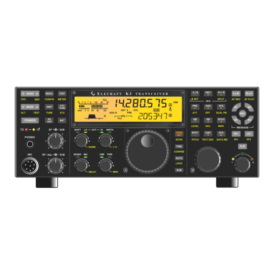
ELECRAFT K3 Installation Instructions Manual
High-performance 160 – 6 meter transceiver
Hide thumbs
Also See for K3:
- Assembly manual (84 pages) ,
- Owner's manual (82 pages) ,
- Installation and operation manual (55 pages)
Summary of Contents for ELECRAFT K3
- Page 1 LECRAFT 160 – 6 M ERFORMANCE ETER RANSCEIVER KIO3B I NTERFACE PTION NSTALLATION NSTRUCTIONS Revision A2, February 5, 2016 E740280 Copyright © 2016, Elecraft, Inc. All Rights Reserved...
-
Page 2: Table Of Contents
Monitoring RS232 Data .......................... 13 Customer Service and Support ....................... 15 Technical Assistance ............................. 15 Repair / Alignment Service ........................... 15 Appendix A – K144XV Cabling ......................16 Elecraft manuals with color images may be downloaded from www.elecraft.com. -
Page 3: Introduction
It also has monaural microphone and isolated line inputs. Bias for an electret microphone can be provided at the microphone input using the K3 menu. The analog inputs and outputs are available even when the USB interface is being used. -
Page 4: Tools Required
Use the screwdriver that best fits the screw in each step. 2. Wrench to remove jack screw nuts on the K3 back panel. A 3/16” nut driver is recommended. 3. Small needle-nose pliers or tweezers to position small parts. -
Page 5: Installation Procedure
Installation Procedure Removing the Top Cover Disconnect power and all cables from your K3. Remove the nine screws to free the top cover as shown in Figure 1. After the cover is open, lift it gently to reach the speaker wire connector. Unplug the speaker. If the K144XV is installed, slip the connector under the stiffener at the depression in the cover of the K144XV module (see Figure 12 on page 11). - Page 6 Remove the seven screws shown in Figure 2 to free the panel and lift the panel off of the K3. Note that Screw 1 is not the screw through the side panel, but is the screw through the lip at the top of the rear panel. This will free the 2D fastener inside to come off with the side panel, which will make removing the existing KIO3 board easier, especially if you have the KRX3 sub receiver installed.
- Page 7 Remove the KIO3 board upper standoff (see Figure 4). Take care not to lose the screw or lock washer inside the K3. You can temporarily stand the K3 on the open side so if you drop the hardware it will fall onto your bench and not inside the K3.
- Page 8 Figure 6. Mounting the Standoff and Audio I/O Board on the KIO3B Main Board. Plug the KIO3B main board into the J76 on the K3 RF board (the same connector used by the original KIO3 board, see Figure 5). Be sure all the pins engage the connector.
- Page 9 Figure 8. Mounting the new KIO3B Rear Panel Cover. Turn the K3 so you can see the component side of the KIO3B main board and locate the USB/RS232 switch (see Figure 9). Place the switch in the USB/RS232 position as shown (toggle to the right looking at the switch).
- Page 10 K144XV connectors after the side panel is in place. Hint: Stand the K3 on its side feet as you did to remove the panel and hold tension on the two TMP cables for the K144XV to keep them in the notch while you put the side panel in place.
- Page 11 If the K144XV 2-meter option and KRX3 sub receiver are installed be sure the 12V power cable is routed as shown in Figure 11 so the cable is not trapped between the speaker and top of the sub receiver enclosure. Figure 11.
-
Page 12: Initial Setup
VFO A display. If your pc is RS232 turned on, it will power up the USB interface and recognize the KIO3B USB port even if the K3 is turned off or the configuration is not properly set. You must set the configuration to before your pc can communicate with the K3 itself. -
Page 13: Forcing A Firmware Download Using The Usb Interface
P3’s menu. If desired you can connect your K3 to a computer with a USB port as shown in Figure 14, but to maintain full functionality of the P3 interface you will need the special cable shown in the figure. Order cable CBLP3Y. Set the RS232 baud rate to as described under USB Computer Interface above. - Page 14 Figure 13. P3 Cabling for RS232 Computer Interface. Figure 14. P3 Panadapter Cabling for USB Computer Interface.
-
Page 15: Customer Service And Support
Repair / Alignment Service (We want to make sure everyone succeeds!) If necessary, you may return your Elecraft product to us for repair or alignment. (Note: We offer unlimited email and phone support to get your kit running, so please try that route first as we can usually help you find the problem quickly.) -
Page 16: Appendix A - K144Xv Cabling
Figure 16. If you have the optional K144XV Ref Lock installed and your K3 has the original synthesizers (with a large toroidal inductor near the center, see Figure 17. Figure 15. Basic K144XV Cabling (No K144XV Ref Lock). - Page 17 Figure 16. K144XV Cabling with KSYN3A and K144 Ref Lock. Figure 17. K144XV with K144XV Ref Lock and Original Synthesizers.


Need help?
Do you have a question about the K3 and is the answer not in the manual?
Questions and answers