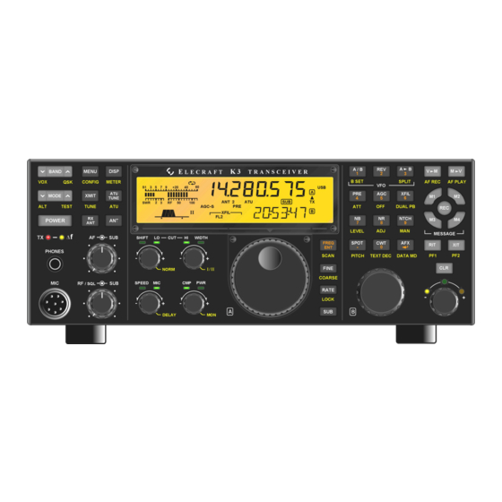
ELECRAFT K3 Installation Manual
High-performance 160-6 meter transceiver
Hide thumbs
Also See for K3:
- Assembly manual (84 pages) ,
- Owner's manual (82 pages) ,
- Installation and operation manual (55 pages)

Subscribe to Our Youtube Channel
Related Manuals for ELECRAFT K3


Summary of Contents for ELECRAFT K3
- Page 1 LECRAFT 160 – 6 M ERFORMANCE ETER RANSCEIVER K144XV REFERENCE OSCILLATOR PHASE LOCK OPTION NSTALLATION Revision A2, February 21, 2013 Copyright © 2013, Elecraft, Inc. All Rights Reserved...
-
Page 2: Table Of Contents
Removing the K3Top Cover and Chassis Stiffener ..................6 Installing the Phase Lock Board ........................7 Installing the Firmware and Testing the Board ....................9 Replacing the Top Cover ..........................10 Recalibrating the XV144 ........................11 Elecraft manuals with color images may be downloaded from www.elecraft.com. -
Page 3: Introduction
Elecraft at the time of original order, are not covered by this warranty. If the Elecraft product is being bought indirectly for a third party, the third party's name and address must be provided to Elecraft at time of order to insure warranty coverage. -
Page 4: Installing The K144Xv Phase Lock Board
Installing the K144XV Phase Lock Board Anti Static Protection Required We strongly recommend you take the following anti-static precautions (listed in order of importance) to avoid ESD (Electro Static Discharge) damage: Leave ESD-sensitive parts in their anti-static packaging until you install them. The packaging may be a special plastic bag or the component’s leads may be inserted in conductive foam. -
Page 5: Parts Included
Parts Included The following parts should be included in your kit. Check to ensure you have them all. If any parts are damaged or missing, contact Elecraft for replacements (see Customer Service and Support, page 3). ELECRAFT ILLUSTRATION DESCRIPTION QTY. -
Page 6: Installation Procedure
Remove the stiffener bar that runs from side to side across the top of the K3 chassis. This is the bar the three screws across the center of the top cover thread into. The bar is held in place by a single screw at each side and, if the KPA3 100 watt option is installed, by two screws attaching it to the KPA3 shield. -
Page 7: Installing The Phase Lock Board
Installing the Phase Lock Board The K144XV module is mounted on the left side panel of the K3. Remove the five screws shown in Figure 2 and lift the top cover off of the module. Note: Some units may have a sixth screw in the hole near the Elecraft name on the top cover that must be removed. - Page 8 Connect the TMP cables as shown in Figure 4. The TMP cables are simple friction-fit connectors but must be properly aligned when inserted (see Figure 5). Disconnect the TMP cable from J2 on the KREF3 board and plug it into the TMP connector on the Phase Lock board.
-
Page 9: Installing The Firmware And Testing The Board
K144XV Utility program. Turn on your K3 while watching the STATUS LED on the K144XV module. It should flash once or twice, indicating normal operation and that it is ready for firmware. (If the STATUS LED remains on, the K144XV module MCU has failed to initialize properly. -
Page 10: Replacing The Top Cover
Figure 7. Connecting the Speaker Cable. Position the top cover on the K3. Note that the tab on the back center goes under the rear lip of the K3 rear panel. Secure the top cover with the nine 4-40 3/16” (4.8 mm) black flat head screws you removed earlier (see Figure 1 on page 6 for the screw locations). -
Page 11: Recalibrating The Xv144
K3’s LCD. The automatically calculated offset will REFLOCK appear in upper half of the K3’s LCD. This enables reflock for both the 144 and 146 MHz band segments. You don’t have to repeat the procedure for each segment.
Need help?
Do you have a question about the K3 and is the answer not in the manual?
Questions and answers