ELECRAFT K4 Operating Manual
Hide thumbs
Also See for K4:
- Introduction manual (41 pages) ,
- Programmer's reference manual (35 pages) ,
- Operating manual (132 pages)

Related Manuals for ELECRAFT K4


Summary of Contents for ELECRAFT K4
-
Page 1: Table Of Contents
ELECRAFT K4 OPERATING MANUAL Rev C9 Table of Contents I. INTRODUCTION USING THE BUILT-IN OPERATING MANUAL K4 TRANSCEIVER OVERVIEW INSTALLATION INSTRUCTIONS REAR PANEL CONNECTIONS II. FRONT PANEL REFERENCE USING TAP, HOLD, and TOUCH CONTROLS FRONT PANEL OVERVIEW LEFT-SIDE CONTROLS MULTI-FUNCTION CONTROLS... - Page 2 BAND SELECTION ANTENNA SELECTION OPERATING MODES RECEIVER SETTINGS TRANSMITTER SETTINGS TX AND RX METERING PANADAPTER DUAL RECEIVE HDR RECEIVE (K4HD) AUDIO EFFECTS (AFX) DIGITAL VOICE RECORDER (DVR) USING THE STATUS DISPLAY FREQUENCY MEMORIES USING SPLIT INTERNAL & EXTERNAL TRANSVERTERS REMOTE CONTROL MACRO PROGRAMMING RTTY CONFIGURATION FT8 / JT / ETC.
-
Page 3: Introduction
This operating manual is a compact reference to all K4 controls, connectors, display elements, and menu entries. It also provides context-sensitive help during operation. Please refer to the Elecraft K4 Owner's Manual for more detailed instructions on all topics. At minimum, please read the fully illustrated short-form manual, Introduction to the Elecraft K4, to become familiar with control and connector locations. -
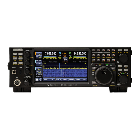
Page 4: K4 Transceiver Overview
VHF up. Among the K4's notable features: A large color touch screen, as well as support for an external monitor; extensive, easy to use controls; rich analog and digital connectivity; dual receive; built-in data modes, and wide range antenna tuner. -
Page 5: Installation Instructions
(QSB). A basic K4 can be upgraded to a K4D by installing the KRX4 option. Similarly, a K4D can be upgraded to a K4HD by installing a KHDR4 module. Other internal options and external accessories are applicable to all three models, including a wide-range ATU (KAT4), MH4 microphone, SP4 external speaker (1 or 2). - Page 6 Using the Tilt Stand If the K4 is placed on a desk or table, deployment of the tilt stand is strongly recommended to facilitate easier interaction with the touch screen. This will also improve display viewing angle.
-
Page 7: Rear Panel Connections
At minimum you'll need to connect a power supply, antenna, and station ground. Getting Started Once your K4 is installed and you're ready to operate, you can get started in one of two ways: (1) read the FRONT PANEL REFERENCE... - Page 8 INSTRUCTIONS. TX SMPL IN If transmit IMD optimization** is enabled for use with an external linear amplifier (such as the Elecraft KPA1500), connect its transmit output sample port to TX SMPL IN. Refer to the owner's manual for signal level and calibration details.
- Page 9 OUT). LINE OUT is stereo; LINE IN is mono. Connect the cable to any USB-A jack on a host computer or hub. To set the baud rates for these ports, use the Serial USB-PCn: Baud Rate menu entries. Refer to software application manuals for port setup instructions. (Plugging in new devices, including the K4,...
- Page 10 Ext. Monitor Function LCD SCREEN AND TOUCH CONTROLS. REF IN A 10 MHz reference signal may be connected to this jack. The K4's internal reference oscillator will lock to this signal when present. Also see ER100 (Error Messages). LINE IN This is an analog audio input (nominally 600 ohms) for connection to computers or other station equipment that supply transmit audio to the K4.
- Page 11 This is an analog audio output (stereo; nominally 600 ohms) for connection to computers or other station equipment that obtain receive audio from the K4. An example of this is a software application that demodulates data-mode audio signals such as FT8, RTTY, or PSK31, as well as CW signals.
- Page 12 RS-232 This DE9 connector provides a true-RS232 COM port that can be used for remote control of the K4. The K4 can also emit Auto-Info (AI) frequency data on this port for use with external devices such as antenna controllers.
- Page 13 KEY Out to RF Out. PADDLE 1/4" (6.35 mm) keyer paddle input jack. The dot and dash inputs on this jack activate the K4's built-in CW keyer. To set up Iambic keying mode, reverse the dot/dash paddles, or adjust keying weight, tap the <TX>...
-
Page 14: Front Panel Reference
K4 "power on" signal or TX Inhibit input (see TX Inhibit Mode) Power On; pull to ground (0 V) for 0.2 to 1.0 sec to turn K4 on, then release BAND2 OUT; BAND0-BAND3 outputs provide 4-bit parallel band indication KEY OUT LP; low-power keying output (10 mA max) DIGOUT1;... -
Page 15: Using Tap, Hold, And Touch Controls
Using Tap and Hold Switch Functions Each of the K4's physical switches has both a tap function (white label) and a hold function (yellow label). A tap is a brief press, while a hold is any press longer than about 1/2 second. For example,... -
Page 16: Front Panel Overview
FRONT PANEL OVERVIEW A large (7" diagonal) color LCD forms the heart of the K4's user interface. Most of the screen is dedicated to either a single panadapter (associated with VFO A or VFO B), or split between dual panadapters (centered below the VFO A and VFO B displays, respectively). - Page 17 Front-Panel Connectors There are three connectors on the front panel: The front mic jack is an Elecraft standard 8-pin type. It is compatible with the Elecraft MH4 and other K3/K3S-compatible microphones. Bias, gain, and mic PTT/UP/DOWN controls are configured using <TX>...
-
Page 18: Left-Side Controls
Tap [POWER] to turn the K4's power on or off. NOTE: Always turn the K4 off using its power switch. If you need to turn off the power supply as well, wait until the K4 has completely powered down. (This may take several seconds. You'll hear a number of relays turning off.) - Page 19 XMIT Tap [XMIT] to place the K4 in transmit mode. This is the equivalent of holding a mic PTT button or asserting any of the other PTT lines (e.g., at the PTT IN jack). Tap [XMIT] a second time to exit transmit mode.
- Page 20 Each time you transmit, the K4 makes sure that the stored LC settings closest to your operating frequency are used. For this reason, after you move the VFO and transmit, you may hear relays switching briefly (~10 ms).
- Page 21 QSK is especially useful in contesting, DXing, and high-speed CW QSOs. The K4 actually allows received signals to be heard in this way even with QSK turned off, as long as the radio is in [VOX] mode and the {XMTR} <DLY> value is set to a small value (default is 0.00 seconds).
-
Page 22: Multi-Function Controls
ANTENNA SELECTION. MULTI-FUNCTION CONTROLS The K4 has three multi-function controls, each handling a group of related functions: XMTR, FILTER, and RF/SQL. The knobs incorporate push-button switches which are tapped or held to select among parameters to adjust. Each knob is accompanied by two buttons on the LCD. These buttons each have two labels, one of which is currently available for adjustment. - Page 23 XMTR Knob Rotate {XMTR} to adjust often-used transmit functions. In all operating modes, tapping the lower LCD button adjacent to this knob selects <PWR> output or VOX <DLY> for adjustment. Tapping the upper LCD button selects either <MIC> and <CMP> (in speech modes) or <WPM>...
- Page 24 If the button selector color is blue, the main receiver's passband will be adjusted. If the selector is green, the sub receiver's passband will be adjusted. To select the sub RX for passband adjustment, either tap [B SET] (near the VFO B knob) or tap the <SUB RX> primary function button. Both illuminate the B SET icon.
-
Page 25: Lcd Screen And Touch Controls
AF/SUB Knob (AF Gain) The inner concentric knob, {AF}, sets main receiver AF gain. The outer concentric knob, {SUB}, sets sub receiver AF gain. LCD AND ON-SCREEN CONTROLS The LCD screen is divided into a number of elements as described below. Many of these elements show the current state of settings while also serving as touch controls. - Page 26 K4: <MENU>, <Fn> (special functions), <DISPLAY>, <MAIN RX>, <SUB RX>, and <TX>. For a full description, see PRIMARY FUNCTIONS. VFO A and B Displays Adjacent to each VFO's numeric display is its ID (A in blue, B in green) and operating mode. Mode icons or the [MODE] switch can be tapped to change modes.
- Page 27 S-meters. Normally the K4 transmits on VFO A, so these bar graphs will appear on the left. In SPLIT mode, the K4 transmits on VFO B, so they appear on the right. This serves as a clear reminder to the operator about whether SPLIT is in effect or not.
- Page 28 Status Area The status area, just above the Info button (<?>) at the lower-left corner of the screen, normally shows UTC date and time. Tapping this text brings up the STATUS DISPLAY button group, allowing you to select a different status display, such as your callsign and time, or supply voltage/current/power output/SWR, or main/sub signal levels in relative dB.
- Page 29 (ATU switch); QSK shows whether QSK (fastest break-in CW) is in effect (QSK switch). The "MSG: I/II" icon, above the RIT/XIT box, shows which message bank has been selected for playback. When a message is playing back with auto-repeat, the icon changes to "MSG RPT" and flashes until repeat is cancelled.
-
Page 30: Vfos And Right-Side Controls
Mini-Pan The mini-pan shows a narrow range of spectrum for fine-tuning of signals. (The data points are not simply magnified; they are resampled to ensure high resolution.) To display the mini-pan, tap the S-meter for either receiver. In CW and PSK modes, AUTO-spot centers this signal by automatically adjusting the VFO frequency. In FSK and AFSK modes, the mini-pan cursor identifies the mark tone, while a dotted line shows the space tone. - Page 31 • Delta-F (∆f) indicates that RIT, XIT or SPLIT is in effect • SUB turns on if the sub receiver is in use (see DUAL RECEIVE) • DIV turns on if diversity mode is in enabled (see DIVERSITY MODE) Numeric Keypad Above VFO A is an array of 15 switches that comprise a numeric keypad (0-9, in orange labels).
- Page 32 Frequency Entry and Scanning Tap [FREQ ENT] to directly enter a desired VFO A frequency. To set the VFO B frequency, first tap [B SET], then [FREQ ENT]. Next, enter the desired frequency using the numeric keypad (Numeric Keypad). Entering 1 or 2 digits is interpreted as MHz;...
- Page 33 Sub Receiver and Diversity Mode Tap [SUB] to turn on the sub receiver. When the sub is on, its frequency is controlled by VFO B, except in diversity mode, where both main and sub RX are placed on the frequency of VFO A (see DIVERSITY MODE).
- Page 34 FREQUENCY MEMORIES. Receive Audio Record/Playback The K4 can record and play received audio. Both main and sub audio are recorded and played if the sub receiver was on during record. To bring up receive audio record/play controls, hold [AF REC] PLAY].
- Page 35 RIT/XIT and CLR Tap [RIT] to turn on Receive Incremental Tuning, then rotate the OFS (offset) knob below the switch to tune in a signal. RIT offsets only your receive frequency, not transmit. It is especially helpful when CW stations call you off-frequency. Similarly, [XIT] can be turned on to adjust only your transmit frequency.
-
Page 36: Operating Instructions
** Indicates a feature that is still in development. PRIMARY FUNCTIONS Before putting your K4 on the air, you should become familiar with the primary function buttons located at the lower edge of the LCD screen. These functions, used for basic setup of transmit, receive, and panadapter operation, are described below. - Page 37 You'll need to have a USB flash drive installed in one of the three USB A jacks. Also see MENU:Screen Cap File. Note: There is no "eject" control for the flash drive, as required on some computers. The K4 mounts/unmounts the flash drive (from a software perspective) as needed. DX LIST (F11) Tap <Fn>, then <DX LIST>...
- Page 38 Tap <Fn>, then hold <UPDATE> to go to the K4 software update screen. Tap the <?> button for detailed instructions on how to update software or restore an earlier version. An ethernet connection is generally required for this purpose, though it's also possible to load from a USB flash memory device.
- Page 39 <ANT CFG>: Specifies behavior of the RX ANT switch. See ANTENNA SELECTION. <RX EQ>: Receiver 8-band graphic equalizer. <LINE OUT>: Sets up LINE OUT audio levels. Left and right-channel output can be set independently, or you can tap <LEFT=RIGHT> to set both to the value of the left channel. Note: Windows Sound Control Panel does not accurately show sound input level.
- Page 40 CFG>: Sets up front/rear mic gain and bias. For the front mic only, configures buttons (NONE or UP/DN). For an Elecraft MH4 mic, turn bias on, set preamp gain to 0, and enable all buttons. Mics with low-output elements may require higher preamp gain settings.
- Page 41 (DATA, AFSK), with [VOX] turned on. <ANTIVOX>: Sets anti-VOX level. The higher the level, the less likely that audio from the K4's speaker(s) will trigger voice transmit. The remaining <TX> secondary functions are defined for some operating modes, as described below.
- Page 42 MODES. BAND SELECTION The K4 provides several ways to select the band and operating frequency: • Tap <BAND>, then tap the button corresponding to the desired band. Tapping a given band button more than once cycles through three band-stacking registers, recalling recently used frequencies and modes.
- Page 43 • Tap [RCL] to bring up the frequency memory selection window. You can either scroll to a desired memory and tap the <RCL> touch button, or tap one of [M1]-[M4] to recall a quick memory. (Additional text TBD: memory save, etc.). •...
- Page 44 <TX> <ANT CFG> function. Note: On a basic K4, both receivers will always share the same antenna. The K4D adds a second band-pass filter unit and a second A-to-D converter, allowing the sub receiver to use a different...
- Page 45 These modules can be installed in a basic K4 at any time, converting it to a K4D. Antenna Names Both the ATU antennas and receive antenna jacks can be given names by the user, e.g. "Yagi," "Dipole," etc. These names will then appear as the TX and RX antenna icons in lieu of the default names (ANT1, 2, 3 and RX ANT 1, 2).
- Page 46 diodes. To listen to signals below 1 MHz without attenuation, use a separate receive antenna connected to RX ANT 1 IN or XVTR IN/RX ANT 2 IN, or select an ATU antenna that is not in use by the transmitter. (The current transmit antenna is indicated by its icon, as well as an orange dot in the RX antenna button group.) OPERATING MODES This section discusses basic setup procedures for each of the operating modes.
- Page 47 Using SPOT and AUTO-spot The K4 provides both manual and automatic signal spotting in CW mode, allowing you to match the pitch of stations you call. In CW, FSK, and PSK modes, tapping [SPOT] turns on a spotting tone at a per-mode pitch. The VFO can be adjusted until the signal pitch matches that of the spot tone.
- Page 48 CW Messages The K4 provides 2 banks of 4 message buffers each for use in CW, PSK, and FSK modes. To use CW message buffers: • Tap [REC] to enter message text; this brings up the built-in alphanumeric keyboard. You'll be prompted to tap M1..M4 before entering your text.
- Page 49 VOICE MODES The K4 can obtain voice audio from the front mic, rear mic, or LINE IN (analog or digital), or a combination of these. These selections are made by tapping <TX>, then <MIC INP>. Some operators prefer to use a rear-panel mic to eliminate clutter at the front panel.
- Page 50 TX EQ settings. To set up voice monitoring: • Hold [TEST] to put the K4 in TX TEST mode, so you won’t be transmitting. The TX icon will change to TX Test. • Set {XMTR} <MIC> high enough to hear your voice (typically 10-20).
- Page 51 ANTIVOX until the K4 doesn’t switch to TX mode when listening to a strong signal. • Adjust the VOX delay using {XMTR} <DLY>. A longer value will keep the K4 in transmit mode for a longer period of time, allowing for pauses in speech.
- Page 52 CONFIGURATION). Built-In Data Modes The K4's built-in data modes include FSK (RTTY) and PSK (PSK31 or PSK63). In these modes, you can turn on text decode to have demodulated characters appear on the display. You can also transmit in data modes using your keyer paddle or with a keyboard connected to any of the USB type A jacks.
- Page 53 The K4 will decode PSK or FSK from both receivers simultaneously, using separate windows, if both are configured for text decode. You can also decode CW from one receiver while decoding PSK or FSK on from the other. Characters sent with the keyer paddle or an attached keyboard will appear on the text decoder's TX line.
- Page 54 detailed FT8/JT/etc. setup instructions, see FT8 / JT / ETC. CONFIGURATION. • Like DATA mode, AFSK is also audio-based, but optimized for RTTY. The VFO displays the RTTY mark frequency, and LSB is “normal”. The built-in text decoder can be used in this mode. Compression is internally set to 0.
- Page 55 RECEIVER SETTINGS Receiver Configuration Prior to using the receiver, you should familiarize yourself with the receive configuration functions (MAIN RX RX). These are used to configure RX EQ, LINE OUT, audio effects, text decode, and various per-mode settings. Receiver Controls The following controls are used during normal operation to optimize receiver performance under different conditions.
- Page 56 • Rotate the small inner concentric knob to adjust main receiver AF gain. • Rotate the large outer concentric knob to adjust sub receiver AF gain. RF Gain, Squelch, and Main/Sub Balance These settings are adjusted using the {RF/SQL} knob. The default value for the RF gain controls is -0 (no reduction in RF gain).
- Page 57 • To adjust sub receiver RF gain, use {RF/SQL} <S.RF>. The default value for the squelch controls is 0 (squelch completely open). Typically squelch is used only in FM mode. • To adjust main receiver squelch, use {RF/SQL} <M.SQ>. • To adjust sub receiver squelch, use {RF/SQL} <S.SQ>. Balance between main and sub receiver audio is set by holding the {RF/SQL} knob to bring up the [BAL] function**.
- Page 58 • If you're using both the left and right receive audio channels (i.e., with headphones or dual speakers), you can take advantage of the K4's stereo audio effects. See AUDIO EFFECTS (AFX). • All models of the K4 include simultaneous dual receive on any two HF-6 meter bands. For details on...
- Page 59 HDR RECEIVE (K4HD). • The RX Dyn. Range Optimization menu entry can be used to customize behavior of the K4's analog-to-digital converters (ADCs). In general it should be left at the default setting of ON, which configures the ADCs for best response to very strong signals. The OFF setting will slightly improve preamp-off sensitivity.
- Page 60 • During CW use, many operators will leave <WPM> (internal keyer code speed) as the selected function of {XMTR}. You can tap the knob or its LCD labels to select the other functions as needed: <PTCH> (sidetone pitch), <PWR> (power output), or <DLY> (VOX delay). •...
- Page 61 DVR Transmit Messages. • The K4 provides an ESSB (extended single-sideband) mode for operators who wish to use or experiment with higher-fidelity SSB. Since ESSB increases transmit bandwidth, it should only be used when the operator is certain they're not causing interference to other stations. To turn ESSB on/off and adjust its bandwidth, tap <TX>, then tap <ESSB>.
- Page 62 PANADAPTER The K4 supports independent panadapter displays on the LCD and on the external monitor. Both spectrum and waterfall can be customized to the user's requirements. You can select single panadapter mode (VFO A or B) or dual panadapter mode (VFO A and B).
- Page 63 moves the targeted VFO to the frequency marked by the mouse arrow. Tapping the mouse thumbwheel alternates between VFO A, VFO B, and RIT offset. Using Panadapter Controls To change panadapter settings: • Tap the <DISPLAY> primary function button. This brings up a secondary function button row comprised of all panadapter controls.
- Page 64 All subsequent display operations will apply to the selected display and panadapter until changed. Panadapter Controls List <PAN>: Selects single panadapter (PAN = A or PAN = B) or dual (PAN = A+B). If dual pan is selected, then you also need to specify whether parameter changes are to be applied to panadapter A, B, or both (see above).
- Page 65 <FIXED>, <TRACK>, <SLIDE> (etc.): This function controls how the panadapter display moves with respect to the VFO cursor. The different modes are described below. <FREEZE>: Suspends the panadapter spectrum and waterfall. This is useful in conjunction with screen capture to a file on a flash drive (see Fn). <CURS A>...
- Page 66 Dual Receive with K4D/K4HD The K4D and K4HD models include a fully independent second receiver module (KRX4), with its own set of band-pass filters, preamps, and attenuators. If this module is installed, the K4 will use its filtering to maximize receive performance.
- Page 67 VFO A. The DIV LED above VFO A will turn on. • Be sure to put the main and sub receivers on different antennas. (See Antennas.) The K4 is particularly well suited to diversity use since up to five different antenna inputs are available. Some constraints apply to receiver assignments;...
- Page 68 This section will be completed in conjunction with release of the K4HD model (in progress). AUDIO EFFECTS (AFX) Since the K4 has both left and right audio channels, it can provide simulated stereo or other effects to reduce operating fatigue. This requires the use of stereo headphones or dual external speakers.
- Page 69 Status Display Functions <DATE/TIME>: This is the default status display, showing UTC date and time. If your K4 has an internet connection, the date and time will normally be accurate to within approximately 1 second. Hold <SET>...
- Page 70 FREQUENCY MEMORIES The K4 provides 200 general-purpose frequency memories, as well as 4 Quick Memories per band. General-Purpose Memories To store VFO A and B frequencies in a general-purpose memory: •...
- Page 71 To recall a quick memory: • Tap [RCL]. • Tap [M1]-[M4]. This will also dismiss the frequency memory window. USING SPLIT Normally, VFO A is used for both receive and transmit. In SPLIT mode, the K4 transmits on VFO B.
- Page 72 Each button shows its programmed lower band edge in MHz. External transverter bands obtain their transmit drive from the K4's XVTR OUT jack. They can use either RX ANT 1 or XVTR IN for receive. (Also see Dual Transverter Operation, below).
- Page 73 Dual Transverter Operation Two external transverters can be connected to the K4 for simultaneous use on two different bands. Set up VFO A for one band, and select either RX1 (RX ANT 1) or RX2 (XVTR IN) as the antenna. Set up VFO B for the other band, using the opposite antenna.
- Page 74 Ethernet. For this purpose, the K4 offers a large superset of the K3/K3S command set. For details, please refer to the K4 Programmer's Reference. The K4 also supports type 2 remote access (full emulation--see our K4 page for information on our multi-platform Virtual K4 application**).
- Page 75 In all cases, the K4's DATA mode is used. (To be completed.) _________________________________________________ IV. MENU LISTING The K4 configuration menu has one level (i.e., it is "flat"). Menu settings are infrequently changed, and most can be left at their factory default values.
- Page 76 Using the Menu • Tap <MENU>. Use VFO or the up/down arrow keys to find the desired entry. • Most menu entries are locked to avoid inadvertent editing. To unlock, tap the lock symbol. • To edit, tap the parameter field. Tap the menu entry name field to resume scrolling. •...
- Page 77 AGC Hold Time Sets the hold time for slow AGC. AGC Noise Pulse Reject When this parameter is ON, the DSP will suppress large, periodic noise bursts typical of electrical appliance turn on/off, etc., preventing saturation of AGC and consequent long recovery time. However, when continuous pulse noise is present, the noise blanker (NB) will be much more effective.
- Page 78 Specifies whether the external monitor mirrors the LCD screen or shows only panadapters. Ext. Monitor Location Specifies where the external monitor is physically located in relation to the K4 (left, right, above, below). This allows the mouse cursor to be moved between the LCD screen and external monitor in an intuitive way.
- Page 79 the space tone will appear as lower in frequency on the panadapter and mini-pan, even though it is higher in audio pitch.) FSK Polarity Selects the polarity of FSK keying (via the ACC jack or one of the DTR serial control lines). IP Address The radio's current IP address;...
- Page 80 (at its lower gain setting, 10 dB) with the LNA (20 dB) for a total of 30 dB gain. This setting should only be used for weak-signal work, with low-noise antennas and/or very low atmospheric noise. Note: The K4 can automatically reduce preamp gain if necessary to avoid front-end overload; see MENU:RX Auto Attenuation.
- Page 81 Reference Frequency Specifies the actual frequency of the K4's internal reference oscillator (VCO). This value is calibrated at the factory. Once the value is calibrated, VFOs will typically be accurate to within +/- 1 Hz. This setting can be adjusted if it becomes necessary due to component aging. For that purpose you'll need a known-accurate signal source (such as WWV).
- Page 82 RX Auto Attenuation When the parameter is set to On, the K4 will automatically reduce receiver front-end gain if signals above the usable dynamic range are present. When this happens, the attenuator icons will indicate the amount of inserted attenuation. In addition, the preamp will be turned off if necessary.
- Page 83 LCD and external monitor screens to separate files with this base name, but different suffixes. Serial RS232: Auto Info Sets the Auto-Info mode for this port. The default is NOR (no auto-info). In the AUTO1 setting, the K4 will emit "IF" command responses on certain control changes including VFOs, mode, and RIT. For further details on auto-info ("AI"...
- Page 84 Specifies the function of the RTS pin for this port (OFF, PTT, KEY). Serial USB-PC2: Auto Info Sets the Auto-Info mode for this port. The default is NOR (no auto-info). In the AUTO1 setting, the K4 will emit "IF" command responses on certain control changes including VFOs, mode, and RIT. For further details on auto-info ("AI"...
- Page 85 The level of the 2 tones is approximately 6 dB below the equivalent CW power output, and is not subject to the MIC gain or compression settings. NOTE: At the high end of the K4's power output range, it is possible that the peak power shown on the bar...
- Page 86 It is due to the fact that all class AB amplifiers exhibit some degree of gain compression at the high end of their power range. The K4 limits maximum drive to the final amplifier stage in order to ensure good IMD performance and to remain within safe operating limits.
- Page 87 Sets VFO counts per turn to 100, 200, or 400 counts. Wattmeter Cal Per-band wattmeter calibration value. Can be adjusted to calibrate the K4's internal wattmeter against a known-accurate external instrument. This should be done on a mid band, e.g. 40/30/20 meters.
- Page 88 ANT 2 (sam as XVTR IN) should be selected for the receive antenna, and both the XVTR IN and XVTR OUT signals connected to the transverter's IF jacks. However, the K4 also provides transverter band setups that automate all the required setup. See other XVTR menu entries above, as well as the INTERNAL &...
- Page 89 Consider using a linear rather than switching supply if your antenna or power cables are picking up supply noise. Check your power supply’s on/off switch, voltage, fuses (if applicable), and DC cabling. The K4 provides both voltage and current monitoring in the time/date/status area of the LCD.
- Page 90 If you're using a basic K4 with the receivers set to two different bands, the band-pass filters will be bypassed, exposing the receiver to a wider frequency range. (This does not occur on a K4D or K4HD, since these models have two full sets of band-pass filters.)
- Page 91 (ahead of the ADC), you must change preamp and/or attenuator settings. "COR" indication seen on S-meter, or relay heard switching during receive: Each of the K4's receivers has a Carrier Operated Relay (COR) to provide protection from nearby transmitters. When the "COR"...
- Page 92 If power output is low on a given band, check the following: (1) Supply voltage should be ~14 V as measured at the K4's DC input jack. Voltages as low as 11.0 V may be used at reduced output.
- Page 93 VFO B that's too high in frequency, the low-pass filter would greatly attenuate sub receiver signals. The K4 prevents this from occurring. To get around this limitation, you can do any of the following: (1) turn the sub receiver off; (2) go into SPLIT mode first (to make VFO B the TX VFO), then change the...
- Page 94 (ACC jack). ER12, SET command incompatible with target VFO's mode: An external host application or macro has sent the K4 a SET remote control command that does not apply to the current operating mode.
- Page 95 ER13, GET or SET command not implemented: An external host application or macro has sent the K4 a SET remote control command that has not been implemented. ER14, KPA4 module required for this operation: If a KPA4 amplifier module is installed, set MENU:KPA4 PA Option to ENABLED.
- Page 96 ER25-ER40, KPA500 / KPA1500 error condition: If an Elecraft KPA-series amplifier is connected to the K4, the transceiver can display error conditions related to the amplifier. Please refer to the amplifier manual for details. ER41-ER50: Reserved for future use. ER51, High LPA reflected power; check antenna: High SWR seen at the 10 watt stage resulted in excessive reflected power.
- Page 97 ER60, End of Band: Transmit attempted outside the frequency range of the current ham band. This is only allowed when using the XVTR OUT jack for transmit, or if the K4 has been authorized for MARS use (contact Elecraft for details).
- Page 98 ER100, 10 MHz REF IN signal too low; using internal TCXO: An external 10 MHz reference input was detected that is too low in amplitude to ensure stability. Nominal requirement is +10 dBm. Back to Top...
Need help?
Do you have a question about the K4 and is the answer not in the manual?
Questions and answers