Advertisement
Advertisement
Table of Contents

Subscribe to Our Youtube Channel
Related Manuals for Manhattan Comfort Sheridan NS-5GLF


Summary of Contents for Manhattan Comfort Sheridan NS-5GLF
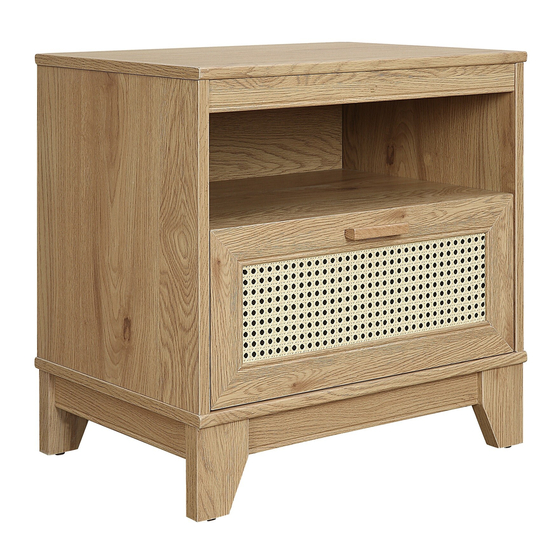
- Page 1 Sheridan Side Table NS-5GLF V.11292022...
-
Page 2: For Best Results
STOP! STOP! Before beginning the assembly process, ensure all boxes and parts have been delivered. FOR BEST RESULTS: • Do not throw away packaging materials until assembly is complete. • Assemble item on a soft surface, such as cardboard or carpet, to protect finish. •... -
Page 3: Included In This Package
Included in this package: A. TOP (1) B. BOTTOM (1) C. LEFT END (1) D. RIGHT END (1) E. SHELF (1) F. BACK (1) G. UPPER BRACE (1) H. DRAWER FRONT (1) J. DRAWER LEFT SIDE (1) K. BRACE (2) L. -
Page 4: Hardware Identification
Hardware Identifi cation Page 4 NS-5GLF... -
Page 5: Warranty Policy
WARRANTY POLICY All Manhattan Comfort furniture products are warranted, to the original purchaser at the time of purchase and for a period of 30 days thereafter. Our warranty is limited to new products purchased in factory sealed cartons. This warranty is valid in the United States of America and Canada. - Page 6 Step 1 Assemble your unit on a carpeted floor or on the empty ◆ carton to avoid scratching your unit or the floor. Turn twenty-four CAM SCREWS (3) into the exact holes shown in ◆ the TOP(A), DRAWER FRONT(H), ENDS (C and D) and FEET (O and Y). Page 6 NS-5GLF...
- Page 7 Step 2 Push eight HIDDEN CAMS (4) into the ENDS (C and D), ◆ BACK(F) and UPPER BRACE(G). Page 7 NS-5GLF...
- Page 8 Step 3 Push sixteen HIDDEN CAMS (4) into the SHELF (E), ◆ DRAWER SIDES (J and P) and LOWER BRACE (L). Page 8 NS-5GLF...
- Page 9 Step 4 Fasten the DRAWER SIDES (J and P) to the DRAWER ◆ BACK (Q). Use four PAN HEAD SCREWS (10). Slide the DRAWER BOTTOM (R) into the grooves in the ◆ DRAWER SIDES (J and P) and DRAWER BACK (Q). Page 9 NS-5GLF...
- Page 10 Step 5 Fasten the DRAWER FRONT (H) to the DRAWER SIDES (J and P). ◆ Tighten four HIDDEN CAMS. NOTE: Be sure the DRAWER BOTTOM (R) inserts into the groove ◆ of the DRAWER FRONT (H). Page 10 NS-5GLF...
- Page 11 Step 6 Separate the EXTENSION SLIDES (2) from the EXTENSION RAILS (1) as shown in the enlarged diagram below. Be ◆ prepared, the parts are greasy. Fasten the EXTENSION SLIDES (2) to the DRAWER SIDES (P and J). Use four FLAT ◆...
- Page 12 Step 7 Fasten the EXTENSION RAILS (1) to the ENDS (C and D). Use four FLAT ◆ HEAD SCREWS (12) Page 12 NS-5GLF...
- Page 13 Step 8 Fasten the SHELF (E) to the ENDS (C and D). Tighten four ◆ HIDDEN CAMS Page 13 NS-5GLF...
- Page 14 Step 9 Insert one WOOD DOWEL (9) into the TOP (A). ◆ ◆ Fasten the UPPER BRACE (G) to the TOP (A). Tighten two HIDDEN CAMS. Page 14 NS-5GLF...
- Page 15 Step 10 ◆ Fasten the TOP(A) to the ENDS (C and D). Tighten four HIDDEN CAMS. Page 15 NS-5GLF...
- Page 16 Step 11 Insert one WOOD DOWEL (9) into the TOP (A). ◆ Fasten the BACK (F) to the TOP (A). Tighten two HIDDEN CAMS ◆ Page 16 NS-5GLF...
- Page 17 Step 12 Insert three WOOD DOWEL (9) into ENDS (C and D) and BACK (F). ◆ Fasten the BOTTOM (B) to the BACK (F) and the ENDS (C and D). ◆ Use six PAN HEAD SCREWS (10) Page 17 NS-5GLF...
- Page 18 Step 13 Fasten four METAL PLATE to the FOOT (O and Y) and the BRACES (K). ◆ Use sixteen PAN HEAD SCREWS. Page 18 NS-5GLF...
- Page 19 Step 14 Fasten eight BRACKETS to the BRACES (K) and the LOWER BRACES (L). ◆ Use eight PAN HEAD SCREWS (13). Page 19 NS-5GLF...
- Page 20 Step 15 ◆ Faten two BRACES (L) to the FOOT (Y and O). Tighten eight HIDDEN CAMS. Page 20 NS-5GLF...
- Page 21 Step 16 ◆ Fasten the BASE to the BOTTOM (B). Use eight PAN HEAD SCREWS (13). Page 21 NS-5GLF...
- Page 22 Step 17 Carefully stand your unit upright. ◆ To insert the DRAWER (H) into your unit, line up the EXTENSION SLIDES on the drawer with the EXTENSION RAILS on the unit and push the drawer into the unit until the drawer is fully inserted. The drawer will push in hard until ◆...
- Page 23 Step 18 Peel APPLIQUES from the APPLIQUE CARDS (5) ◆ and stick them onto each visible HIDDEN CAM. Page 23 NS-5GLF...
- Page 24 Step 19 NS-5GLF Page 24...
Need help?
Do you have a question about the Sheridan NS-5GLF and is the answer not in the manual?
Questions and answers