Table of Contents
Advertisement
Available languages
Available languages
Quick Links
ID
SYS
CON
ETH
S58 50- 16T
16B S2Q
S5850-16T16BS2Q
ETHERNET L3 SWITCH
ETHERNET L3 SWITCH
SWITCH ETHERNET L3
イーサネットL�スイッチ
Quick Start Guide
Quick-Start Anleitung
Guide de Démarrage Rapide
クイックスタートガイド
17
18
19
1
2
3
4
5
6
7
8
9
10 11
12 13
14 15
16
40G
1
2
3
4
40G E Brea
kout
V1.0
20 21
22 23
24
25
26
27
28
29
30 31
32
33
34
Advertisement
Table of Contents

Subscribe to Our Youtube Channel
Related Manuals for FS S5850-16T16BS2Q


Summary of Contents for FS S5850-16T16BS2Q
- Page 1 16B S2Q 20 21 22 23 30 31 10 11 12 13 14 15 40G E Brea kout S5850-16T16BS2Q ETHERNET L3 SWITCH ETHERNET L3 SWITCH SWITCH ETHERNET L3 イーサネットL�スイッチ Quick Start Guide V1.0 Quick-Start Anleitung Guide de Démarrage Rapide クイックスタートガイド...
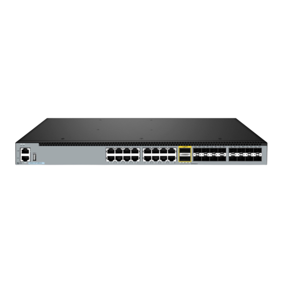
- Page 2 Introduction Thank you for choosing the S5850-16T16BS2Q Ethernet L3 Switch. This guide is designed to familiarize you with the layout of the switch and describes how to deploy it in your network. 20 21 22 23 30 31 S5850-16T16BS2Q 10 11...
-
Page 3: Hardware Overview
Front Panel Ports QSFP+ 20 21 20 21 20 21 22 23 22 23 22 23 30 31 30 31 30 31 S5850-16T16BS2Q S5850-16T16BS2Q S5850-16T16BS2Q 10 11 10 11 10 11 12 13 12 13 12 13 14 15 14 15... -
Page 4: Installation Requirements
LEDs State Description The ID indication function is enabled. Blue The ID indication function is disabled. Green The system is normally running. Orange An alarm or error occurs in the system. No power or the system is not running or is in abnormality. -
Page 5: Safety Precautions
Safety Precautions: The power source should be removed before cleaning the device. Do not use wet rags to wipe the device or clean the device with liquid. The device shall work normally under the correct voltage, so make sure the operating voltage agrees with the voltage marked on the device. -
Page 6: Mounting The Switch
Mounting the Switch SY S CO N ET H Desk Mounting S5 85 0- 16 T1 6B S2 Q S5 85 0-1 6T 16 BS 12 13 14 15 40G E Brea kou t 1. Attach four rubber pads to the bottom of the switch. 2. -
Page 7: Grounding The Switch
20 21 22 23 30 31 SY S 10 11 12 13 14 15 CO N 40 GE Bre ako ut ET H S5 85 0- 16 2. Attach the switch to the rack using screws and cage nuts. Grounding the Switch SY S CO N ET H... -
Page 8: Connecting The Sfp+ Ports
Connecting the RJ45 Ports SY S CO N ET H S5 85 0- 16 T1 6B S2 Q 6T 16 B S2 20 21 22 23 30 31 10 11 12 13 14 15 40 G 40 GE Br ea ko ut 1. - Page 9 Connecting the SFP28 Ports 20 21 22 23 30 31 10 11 12 13 14 15 40 G 40 GE Br ea ko ut 1. Plug the compatible SFP28 transceiver into the SFP28 port. 2. Connect a ber optic cable to the ber transceiver. Then connect the other end of the cable to another ber device.
-
Page 10: Connecting The Console Port
Connecting the Console Port SY S CO N ET H S5 85 0- 16 T1 6B S2 Q 1. Insert the RJ45 connector into the RJ45 console port on the switch. 2. Connect the DB9 female connector of the console cable to the serial port on the computer. -
Page 11: Connecting The Usb Port
Connecting the USB Port SY S CO N ET H S 58 50 -1 6T 16 B S 2Q 20 21 22 23 30 31 10 11 10 11 12 13 14 15 40 GE Bre ako ut Insert the Universal Serial Bus (USB) ash disk into the USB port for software and con guration backup and o ine software upgrade. - Page 12 Con guring the Switch Con guring the Switch Using the Web-Based Interface Step 1: Connect a computer to the Ethernet port of the switch using the network cable. Step 2: Set the IP address of the computer to 192.168.1.x ("x" is any number from 2 to 254). 20 21 22 23 30 31...
- Page 13 Con guring the Switch Using the Console Port Step 1: Connect a computer to the console port of the switch with the console cable. Step 2: Start the terminal simulation software, such as HyperTerminal on the computer. Step 3: Set the parameters of the HyperTerminal: Baud rate to 115200, Data bits to 8, Parity to None, and Stop bits to 1.
-
Page 14: User Password Lost
Troubleshooting Loading Failure Re-check if physical port connections are good rst. If some ports are not connected, then re-connect them and begin re-loading. If physical connections are correct, then check the loading process information displayed on the super terminal to verify if there are input errors. If so, correct them and re-load. -
Page 15: Online Resources
Product Warranty FS ensures our customers that for any damage or faulty items due to our workmanship, we will o er a free return within 30 days from the day you receive your goods. This excludes any custom-made items or tailored solutions. - Page 16 Einführung Vielen Dank, dass Sie sich für den Ethernet L3 Switch S5850-16T16BS2Q entschieden haben. Dieses Handbuch soll Sie mit dem Aufbau des Switches vertraut machen und beschreibt, wie Sie ihn in Ihrem Netzwerk einsetzen. 20 21 22 23 30 31...
- Page 17 Ports an der Vorderseite QSFP+ 20 21 20 21 20 21 22 23 22 23 22 23 30 31 30 31 30 31 S5850-16T16BS2Q S5850-16T16BS2Q S5850-16T16BS2Q 10 11 10 11 10 11 12 13 12 13 12 13 14 15 14 15...
- Page 18 LEDs Status Beschreibung Die ID-Anzeigefunktion ist aktiviert. Blau Die ID-Anzeigefunktion ist deaktiviert. Grün Das System läuft normal. Orange Im System tritt ein Alarm oder Fehler auf. Kein Strom oder das System läuft nicht oder es liegt eine Störung vor. Der 1G-Port ist nicht verbunden. Grün Blinkt Es werden 1G-Pakete empfangen oder übertragen.
- Page 19 Vorsichtsmaßnahmen: Vor der Reinigung des Geräts sollte der Strom getrennt werden. Wischen Sie das Gerät nicht mit nassen Tüchern ab und reinigen Sie es nicht mit Flüssigkeiten. Das Gerät sollte nur mit der richtigen Spannung betrieben werden. Stellen Sie sicher, dass die Betriebsspannung mit der auf dem Gerät angegebenen Spannung übereinstimmt.
- Page 20 Montage des Schalters SY S CO N Tischmontage ET H S5 85 0- 16 T1 6B S2 Q S5 85 0-1 6T 16 BS 12 13 14 15 40G E Brea kou t 1. Befestigen Sie vier Gummipads an der Unterseite des Switches. 2.
- Page 21 20 21 22 23 30 31 SY S 10 11 12 13 14 15 CO N 40 GE Bre ako ut ET H S5 85 0- 16 2. Befestigen Sie den Switch mit Schrauben und Kä gmuttern am Rack. Erdung des Switches SY S CO N ET H...
- Page 22 Anschließen der RJ45-Ports SY S CO N ET H S5 85 0- 16 T1 6B S2 Q 6T 16 B S2 20 21 22 23 30 31 10 11 12 13 14 15 40 G 40 GE Br ea ko ut 1.
- Page 23 Anschließen der SFP28-Ports 20 21 22 23 30 31 10 11 12 13 14 15 40 G 40 GE Br ea ko ut 1. Stecken Sie den kompatiblen SFP28-Transceiver in den SFP28-Port. 2. Schließen Sie ein LWLW-Kabel an den Glasfaser-Transceiver an. Schließen Sie dann das andere Ende des Kabels an ein anderes Glasfasergerät an.
- Page 24 Anschließen des Console-Ports SY S CO N ET H S5 85 0- 16 T1 6B S2 Q 1. Stecken Sie den RJ45-Steckverbinder in den RJ45-Console-Port des Switches. 2. Verbinden Sie die DB9-Buchse des Console-Kabels mit dem seriellen Port des Computers. Anschließen des ETH-Ports SY S CO N...
-
Page 25: Anschließen Der Stromversorgung
Anschließen des USB-Ports SY S CO N ET H S 58 50 -1 6T 16 B S 2Q 20 21 22 23 30 31 10 11 10 11 12 13 14 15 40 GE Bre ako ut Stecken Sie das USB-Laufwerk (Universal Serial Bus) in den USB-Port, um die Software und die Kon guration zu sichern und die Software o ine zu aktualisieren. - Page 26 Kon gurieren des Switches Kon gurieren des Switches über der webbasierten Schnittstelle Schritt 1: Schließen Sie einen Computer über ein Netzwerkkabel an den Ethernet-Port des Switches an. Schritt 2: Stellen Sie die IP-Adresse des Computers auf 192.168.1.x ein ("x" ist eine beliebige Zahl zwischen 2 und 254).
-
Page 27: Fehlerbehebung
Schritt 4: Klicken Sie auf Login, um die webbasierte Kon gurationsseite anzuzeigen. Kon gurieren des Switches über den Console-Port Schritt 1: Schließen Sie einen Computer über das Console-Kabel an den Console-Port des Switches an. Schritt 2: Starten Sie die Terminalsimulationssoftware, z. B. HyperTerminal, auf dem Computer. - Page 28 Wenn die physischen Verbindungen in Ordnung sind und während des Ladevorgangs keine Eingabefehler auftreten, der Ladevorgang aber dennoch fehlschlägt, wenden Sie sich bitte an Fachpersonal, um Hilfe zu erhalten. Benutzerkennwort verloren Wenn Sie das Systempasswort verloren oder vergessen haben, rufen Sie den uBoot- Betriebsmodus auf und geben Sie den Befehl boot_ ash_nopass ein, um das System im uBoot-Modus zu starten.
- Page 29 Kontakt https://www.fs.com/de/contact_us.html Produktgarantie FS garantiert seinen Kunden, dass wir bei Schäden oder fehlerhaften Artikeln, die auf unsere Verarbeitung zurückzuführen sind, eine kostenlose Rückgabe innerhalb von 30 Tagen nach Erhalt der Ware anbieten. Dies gilt nicht für Sonderanfertigungen oder maßgeschneiderte Lösungen.
- Page 30 Introduction Nous vous remercions d'avoir choisi le switch Ethernet L3 S5850-16T16BS2Q. Ce guide est conçu pour vous familiariser avec la con guration du switch et indique comment procéder à son déploiement. 20 21 22 23 30 31 S5850-16T16BS2Q 10 11...
-
Page 31: Présentation Du Matériel
Ports du Panneau Frontal QSFP+ 20 21 20 21 20 21 22 23 22 23 22 23 30 31 30 31 30 31 S5850-16T16BS2Q S5850-16T16BS2Q S5850-16T16BS2Q 10 11 10 11 10 11 12 13 12 13 12 13 14 15 14 15... -
Page 32: Conditions D'installation
Allumé La fonction d'indication de l'ID est activée. Bleu Éteint La fonction d'indication d'ID est désactivée. Vert Allumé Le système fonctionne normalement. Orange Allumé Une alarme ou une erreur est détectée dans le système. Le système n'est pas alimenté, ne fonctionne pas Éteint ou présente une anomalie. - Page 33 Un rack standard de 19 pouces de large avec un minimum de 1U de hauteur disponible. Câbles à bre optique pour la connexion des périphériques réseau. Précautions : La source d'alimentation doit être retirée avant de nettoyer l'appareil. Ne pas utiliser de chi ons mouillés ou de liquides pour nettoyer l'appareil.
-
Page 34: Installation Sur Bureau
Installation du Switch SY S CO N Installation sur Bureau ET H S5 85 0- 16 T1 6B S2 Q S5 85 0-1 6T 16 BS 12 13 14 15 40G E Brea kou t 1. Fixez quatre patins en caoutchouc à la base du switch. 2. - Page 35 20 21 22 23 30 31 SY S 10 11 12 13 14 15 CO N 40 GE Bre ako ut ET H S5 85 0- 16 2. Fixez le switch au rack à l'aide de vis et d'écrous à cage. Mise à...
- Page 36 Connexion des Ports RJ45 SY S CO N ET H S5 85 0- 16 T1 6B S2 Q 6T 16 B S2 20 21 22 23 30 31 10 11 12 13 14 15 40 G 40 GE Br ea ko ut 1.
- Page 37 Connexion des Ports SFP28 20 21 22 23 30 31 10 11 12 13 14 15 40 G 40 GE Br ea ko ut 1. Branchez l'émetteur-récepteur SFP28 compatible dans le port SFP28. 2. Connectez un câble à bre optique à l'émetteur-récepteur à bre optique. Connectez ensuite l'autre extrémité...
- Page 38 Connexion du Port Console SY S CO N ET H S5 85 0- 16 T1 6B S2 Q 1. Insérez le connecteur RJ45 dans le port de console RJ45 du switch. 2. Connectez le connecteur femelle DB9 du câble de console au port série de l'ordinateur. Connexion du Port ETH SY S CO N...
-
Page 39: Branchement De L'alimentation
Connexion du Port USB SY S CO N ET H S 58 50 -1 6T 16 B S 2Q 20 21 22 23 30 31 10 11 10 11 12 13 14 15 40 GE Bre ako ut Insérez le dispositif USB (Universal Serial Bus) dans le port USB pour la sauvegarde, la con guration ou la mise à... - Page 40 Con guration du Swich Con guration du Switch à l'Aide de l'Interface Web Étape 1 : Connectez un ordinateur au port Ethernet du switch à l'aide du câble réseau. Étape 2 : Réglez l'adresse IP de l'ordinateur sur 192.168.1.x ("x" est un nombre quelconque compris entre 2 et 254).
-
Page 41: Dépannage
Étape 4 : Cliquez sur Login pour a cher la page de con guration basée sur le web. Con guration du Swich à l'Aide du Port Console Étape 1 : Connectez un ordinateur au port de console du switch à l'aide du câble de console. Étape 2 : Lancez le logiciel HyperTerminal sur l'ordinateur. - Page 42 Perte du Mot de Passe Utilisateur Si le mot de passe du système est perdu ou oublié, veuillez entrer dans le mode d'opération uBoot et saisir la commande boot_ ash_nopass pour démarrer le système en mode uBoot, puis vous pouvez réinitialiser le mot de passe. ATTENTION : Après avoir utilisé...
- Page 43 Garantie des Produits FS garantit à ses clients que tout article endommagé ou défectueux en raison de sa fabrication pourra être retourné gratuitement dans un délai de 30 jours à compter de la date de réception de la marchandise. Cette garantie ne s'applique pas aux articles fabriqués sur mesure ou aux solutions personnalisées.
- Page 44 イントロダクション このたびは、S����-��T��BS�QイーサネットL�スイッチをお買いあげいただき、誠にあり がとうございます。本ガイドは、ネットワークパケットブローカーの概要とネットワーク への導入方法について説明します。 20 21 22 23 30 31 S5850-16T16BS2Q 10 11 12 13 14 15 40GE Breakout S����-��T��BS�Q アクセサリー 電源コード x� コンソールケーブル x� LANケーブル x� アースケーブル x� ゴムパッド x� M�ネジ x� 取付けブラケット x� M�ネジ x� M�ケージナット x� スプリングクリップ x�...
- Page 45 フロントパネルポート QSFP+ 20 21 20 21 20 21 22 23 22 23 22 23 30 31 30 31 30 31 S5850-16T16BS2Q S5850-16T16BS2Q S5850-16T16BS2Q 10 11 10 11 10 11 12 13 12 13 12 13 14 15 14 15 14 15...
- Page 46 状態 内容 点灯 ID表示機能が有効です。 青 消灯 ID表示機能が無効です。 緑 点灯 システムは正常に作動しています。 橙 点灯 システムにアラームまたはエラーが発生しています。 電源が入らない、システムが動かない等の異常があり 消灯 ます。 点灯 �Gポートがリンクされています。 緑 点滅 �Gパケットを受信または送信しています。 ETH/RJ�� 点灯 ��/���Mポートがリンクされています。 (�~��) 橙 点滅 ��/���Mパケットを受信または送信しています。 消灯 ポートがリンクされていません。 点灯 ��Gポートがリンクされています。 緑 点滅 ��Gパケットを受信または送信しています。 点灯 ポートはブレークアウトモードになっています。 QSFP+ (��~��) 橙 ブレークアウトポートパケットが受信または送信さ...
- Page 47 最低�Uの高さが利用可能な標準サイズの��インチ幅ラック ネットワーク機器を接続する用の光ファイバケーブル 安全上のご注意: デバイスを清掃する前に、電源を取り外してください。 濡れた布を使用してデバイス を拭いたり、液体でデバイスを清掃したりしないでください。 デバイスは正しい電圧下で正常に動作するため、動作電圧がデバイスにマークされて いる電圧と一致していることを確認してください。 感電の危険を軽減するため、デバイスの動作中は筐体を取り外さないでください。ま た、電源が入っていない場合でも、勝手に筐体を取り外さないでください。 インターフェースボードを交換するときは、静電気によるベニヤの損傷を防ぐために、 静電気防止手袋を着用する必要があります。 デバイスのオプションの光インターフェイスが動作モードのときは、光インターフェイ スを直接見つめないでください。 環境要件: 設置場所の温度を�℃~��℃、相対湿度は��%~��%に保ってください。 換気の良い場所に設置してください。デバイスの周囲に十分な空気の流れがあること を確認してください。 デバイスは、デバイスの側面から少なくとも�U(��.��mm)離して設置する必要があ ります。 危険な状態を避けるために、デバイスが水平で安定していることを確認してください。 粉塵の多い環境に設置しないでください。 設置場所に水漏れ、水滴、結露、湿気がないことを確認してください。 機器室は、SO 、H S、NH 、Cl などの有害ガスの侵入から保護する必要があります。 � � � � 装置を使用する場所は、高出力無線送信所、レーダー送信所、高周波大電流の機器から 離してください。 CO N ラックおよび作業台が十分に接地されていることを確認してください。 S5 85 0- 16 T1 6B S2 Q 雷による過電圧や過電流による装置の信号ポートの損傷を防ぐため、インターフェー...
- Page 48 スイッチのマウント SY S CO N デスクマウント ET H S5 85 0- 16 T1 6B S2 Q S5 85 0-1 6T 16 BS 12 13 14 15 40G E Brea kou t �. �つのゴムパッドをスイッチの底部に取り付けます。 �. スイッチをデスクの上に置きます。 注:�. スイッチの周囲には放熱のため��cm程度のスペースをあけてください。 �. スイッチの上に重いものを置かないでください。 ラックマウント 20 21 22 23 30 31...
- Page 49 20 21 22 23 30 31 SY S 10 11 12 13 14 15 CO N 40 GE Bre ako ut ET H S5 85 0- 16 �. ネジとケージナットを使用してスイッチをラックに取り付けます。 スイッチの接地 SY S CO N ET H S5 85 0- 16 T1 6B S2 Q G P R 15 0- A 1M...
- Page 50 RJ��ポートの接続 SY S CO N ET H S5 85 0- 16 T1 6B S2 Q 6T 16 B S2 20 21 22 23 30 31 10 11 12 13 14 15 40 G 40 GE Br ea ko ut �. イーサネットケーブルをネットワークデバイスのRJ�� ポートに接続します。 �.
- Page 51 SFP��ポートの接続 20 21 22 23 30 31 10 11 12 13 14 15 40 G 40 GE Br ea ko ut �. 互換性のあるSFP��モジュールをSFP��ポートに接続します。 �. 光ファイバケーブルをファイバモジュールに接続します。次に、ケーブルのもう一方の 端を他のファイバデバイスに接続します。 QSFP+ポートの接続 6T 16 B S2 20 21 22 23 30 31 10 11 12 13 14 15 40 G 40 GE Br ea...
- Page 52 コンソールポートの接続 SY S CO N ET H S5 85 0- 16 T1 6B S2 Q �. RJ��コネクタをスイッチのRJ��コンソールポートに挿入します。 �. コンソールケーブルの DB�メスコネクタをコンピュータのシリアル ポートに接続します。 ETHポートの接続 SY S CO N ET H S 58 50 -1 6T 16 B S 2Q 10 11 �. スタンダードRJ��イーサネットケーブルの一端をコンピュータのイーサネットポートに 接続します。...
- Page 53 USBポートの接続 SY S CO N ET H S 58 50 -1 6T 16 B S 2Q 20 21 22 23 30 31 10 11 10 11 12 13 14 15 40 GE Bre ako ut USBフラッシュディスクをUSBポートに挿入し、ソフトウェアと設定のバックアップおよ びオフラインソフトウェアアップグレードを行います。 電源の接続 G P R 15 0- A 1M G P R 15 0- A 1M...
- Page 54 スイッチの設定 ウェブベースのインターフェイスを使用したスイッチの設定 Step �:LANケーブルを使用してコンピュータをスイッチの管理ポートに接続します。 Step �:コンピュータのIPアドレスを���.���.�.x(「x」は�~���の任意の数字)に設定 します。 20 21 22 23 30 31 12 13 40 G 14 15 40 GE Br ea ko ut Step �:ブラウザを開き、「http://���.���.�.�」と入力し、デフォルトのユーザー名とパ スワード「admin/admin」を入力します。 Step �:Loginをクリックすると、ウェブベースの設定ページが表示されます。...
- Page 55 コンソールポートを使用したスイッチの設定 Step �:コンソールケーブルを使用して、コンピュータをスイッチのコンソールポートに 接続します。 Step �:コンピュータ上でHyperTerminalなどのターミナルソフトを起動します。 Step �:HyperTerminalのパラメータを設定します: Baud rate - ������、Data bits - �、 Parity - None、 Stop bits - �。 Step �:パラメータを設定したら、Connectをクリックして接続します。...
- Page 56 トラブルシューティング ローディング失敗 まず物理ポートの接続状態を再確認します。 一部のポートが接続されていない場合は、 それらを再接続し、再ロードを開始します。 物理接続が正しい場合は、スーパーターミナルに表示されるロードプロセス情報を確 認して、入力エラーがないか確認してください。 その場合は、修正して再ロードして ください。 物理的な接続が良好で、読み込みプロセスで入力エラーがないにもかかわらず、最終 的にローディングが失敗する場合は、専門家にご連絡ください。 パスワードを忘れた システムパスワードを紛失または忘れた場合は、uBootオペレーションモードに入り、 boot_flash_nopass コマンドを入力してシステムをuBootモードで起動すると、パスワード をリセットできます。 注:boot_flash_nopassコマンドを使用した後、システムはスタートアップ設 定ファイルをクリアします。この操作を開始する前に、スタートアップ設定ファ イルはflash:/startup-config.conf.old ファイルに保存されます。 電源システムのトラブルシューティング SYSインジケータが消灯している場合、次のことを確認してください: スイッチの電源線が正しく接続されていますか。 スイッチのEPSは、スイッチが必要とする電源と一致します。 設定システムのトラブルシューティング 電源投入後、コンフィグレーション端末に表示情報が表示されない場合は、電源が正 常か、コンフィグレーションポート(コンソール)のケーブルが正しく接続されてい るかを確認してください。 設定端末にハッシュが表示される場合は、端末 (スーパー端末など) のパラメータ設定 を確認してください:baud rate: ������、data bits: �、parity: no、stop bits: �、 flow control: NA、selecting terminal emulation: VT���...
- Page 57 オンラインリソース ダウンロード https://www.fs.com/jp/products_support.html ヘルプセンター https://www.fs.com/jp/service/fs_support.html お問い合わせ https://www.fs.com/jp/contact_us.html 製品保証 FSは、弊社の過失による破損や不良品があった場合、お客様が商品を受け取った日から�� 日以内に無料で返品/交換をすることを保証します。(ただし、特注品やオーダーメイドは 除く) 製品保証:本製品には、�年間の限定保証が付いています。保証の詳細について は、下記のURLからご参照ください。 https://www.fs.com/jp/policies/warranty.html 返品/交換:返品を希望される場合、返品方法については下記のURLからご参照く ださい。 https://www.fs.com/jp/policies/day_return_policy.html...
-
Page 58: Compliance Information
2014/35/EU, 2011/65/EU und (EU)2015/863 konform ist. Eine Kopie der EU- Konformitätserklärung nden Sie unter www.fs.com/de/company/quality_control.html. FS.COM GmbH déclare par la présente que ce dispositif est conforme à la Directive 2014/30/EU, 2014/35/EU, 2011/65/EU et (EU)2015/863. Une copie de la Déclaration de Conformité de l'UE est disponible à l'adresse suivante https://www.fs.com/fr/company/quality_control.html. - Page 59 Caution shock hazard, disconnect all power sources. Attention risque d'électrocution, déconnectez toutes les sources d'alimentation. UKCA Hereby, FS.COM Innovation Ltd declares that this device is in compliance with the Directive SI 2016 No. 1091, SI 2016 No. 1101 and SI 2012 NO. 3032. FS.COM INNOVATION LTD...
- Page 60 Do not dispose of WEEE as unsorted municipal wasteand have to collect such WEEE separately. Q.C. PASSED Copyright © 2023 FS.COM All Rights Reserved.
Need help?
Do you have a question about the S5850-16T16BS2Q and is the answer not in the manual?
Questions and answers