
Related Manuals for Oliver 2003R


Summary of Contents for Oliver 2003R
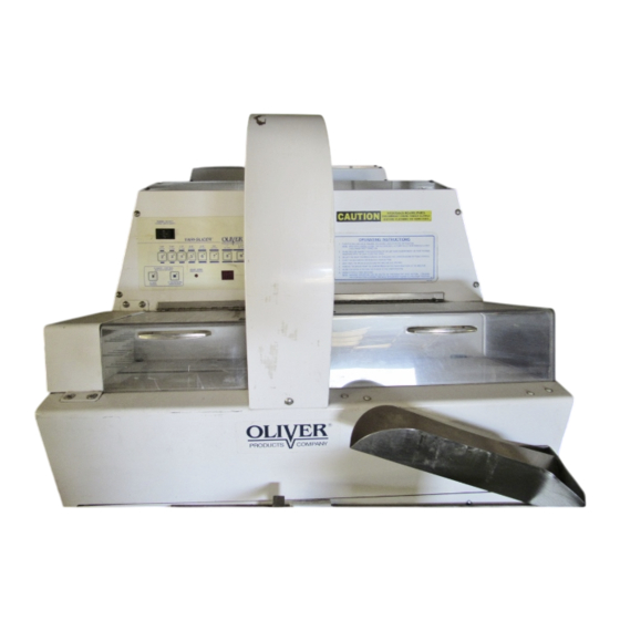
- Page 1 Grand Rapids, Michigan, U.S.A. 49504-5298 USER’S OPERATING AND INSTRUCTION MANUAL MODEL 2003R BREAD SLICER 2003RS20025-CVR...
- Page 2 INDEX Section Page No. SAFETY INSTRUCTIONS..............…….GEN861015 DESCRIPTION/SPECIFICATIONS..........…....2003S20027 OPERATION INSTRUCTIONS..........…....2003S20028 MAINTENANCE...............…....2003S20029 TROUBLESHOOTING............…..2003S20030-1/3 MAIN FRAME ASSEMBLY……………………………………………………...2003S20039 BLADE & CLUTCH ASSEMBLY………………………………………………..2003S20032 CUTOFF ARM ASSEMBLY……………………………………………………..2003S20033 PUSHER WITH STEPPER ASSEMBLY…………………………………..…..2003S20040 TABLE & COVER ASSEMBLY………………………………………...……….2003S20041 CLUTCH ASSEMBLY……………………………………………………………2003S20036 ELECTRICAL SUB-PANEL ASSEMBLY………………………………………2003S20037 ELECTRICS 1-60-115 ASSEMBLY……………………………………………2003S20038 WARRANTY.……………............…..... GEN040225 WARRANTY PROCEDURE................GEN040226 RETURNED PARTS POLICY…………………………………………………...GEN040227 REV.
- Page 3 THIS PAGE WAS INTENTIONALLY LEFT BLANK. GEN020319...
- Page 4 General Document SAFETY INSTRUCTIONS Various safety devices and methods of guarding have been provided on this machine. It is essential, however, that machine operators and maintenance personnel observe the following safety precautions. Improper installation or operation of this equipment may cause injury to personnel or damage to equipment.
- Page 5 DESCRIPTION/SPECIFICATION Description The Oliver Model 2003R is a variable slice thickness bread slicer which utilizes a new and innovative way to slice bread. The bread is moved past a circular blade, which is mounted to a moving arm, cutting each slice individually to whatever thickness is selected.
- Page 6 OPERATING INSTRUCTIONS 1. Automatic Diagnostic Check: Close both doors. Turn the machine on. First the display reads “Vari-slicer” and the software version. Next, the machine will automatically perform a diagnostic check on the “end” and “home” proximity sensors (PS). You should observe the pusher going to its “end”...
- Page 7 MAINTENANCE WARNING DISCONNECT AND LOCK OUT THE MACHINE FROM THE POWER SUPPLY BEFORE CLEANING OR SERVICING. REMEMBER TO USE CARE WHENEVER YOU ARE WORKING NEAR THE BLADE. 1. Cleaning: Use a mild detergent solution applied with a cloth or spray cleaner on all exterior and interior surfaces as necessary.
-
Page 8: Troubleshooting Guide
SUPPLY BEFORE SERVICING. WARNING TROUBLESHOOTING OF THIS EQUIPMENT MUST BE PERFORMED BY QUALIFIED PERSONNEL ONLY. Software on the 2003R is continually performing diagnostic checks on itself. The first diagnostic check occurs when the machine is first turned on. SOLVING SOME PROBLEMS •... - Page 9 SOLVING SOME PROBLEMS- Continued Nothing Happens When The Machine Is Turned On. • Check to see if the machine is plugged in. • Check to see if there is power at the outlet. • Check to see if any of the circuit breakers have tripped. They are located near the lower, right hand, rear corner of the machine.
- Page 10 MANUAL DIAGNOSTIC MODE- Continued 5. Door Test - The display will read "Door Test" and "1=Left 2=Right". Any of the door open sensors can be checked individually by opening the infeed door, the blade guard, or the outfeed door. The display will indicate which is open. Depress the "3" key to continue to the next test.
-
Page 11: Main Frame Assembly
MAIN FRAME ASSEMBLY 2003S20039... -
Page 12: Main Frame Parts List
MAIN FRAME PARTS LIST ITEM NO. PART DESCRIPTION PART NUMBER Cover-Electrical 2003-0021 Track-Crumb Tray 2003-0038 Tray-Crumb 2003-0037 Plate-Face 2003-0003 Frame-Main 2003-0001 Spacer-Angle 2003-0034 Angle-Table Support 2003-0011-1 Bumper-Rubber 5902-0021 *013 Stiffener 2003-0054-1 *Not shown on drawing Rev. 1/25/05 2003S20039... - Page 13 BLADE & CLUTCH DRIVE ASSEMBLY 2003S20032...
- Page 14 BLADE & CLUTCH DRIVE PARTS LIST ITEM NO. PART DESCRIPTION PART NUMBER Motor-Brake 3/4 HP 6301-5611 Screw-Socket Set 5842-6133 Sheave 3L, 2-Grooves 1.5 OD 2003-0070 Belt-V 3L230 5601-1033 Nutbar 2001-0015 Gearmotor 1/8 HP DC (115 VAC) 6310-0008 Pulley-Timing Belt 4495-2816-2001 2003S20032...
- Page 15 CUTOFF ARM ASSEMBLY 2003S20033...
- Page 16 CUTOFF ARM PARTS LIST ITEM NO. PART DESCRIPTION PART NUMBER Block-Pivot Outside 2001-0041 Bearing-Ball 5250-0387 Ring-Retaining #N5000-137 5840-1026 Shaft-Drive 2001-0047-1 Pulley-Timing Belt 2003-0044 Sheave-3L, 2-Grooves 3.882 OD 2003-0071 Ring-Retaining #5100-62 5840-1128 Side-RH Arm 2003-0046-1 Side-LH Arm 2003-0047 Spacer-Aluminum Tube 2003-0050 Trunnion 2003-0052 Washer-Flat 9/32 x 1/8...
- Page 17 PUSHER WITH STEPPER ASSEMBLY 2003S20040...
- Page 18 PUSHER WITH STEPPER PARTS LIST ITEM NO. PART DESCRIPTION PART NUMBER Nutbar-Motor 2001-0110 Motor Assy-Stepper 2003-0023 Gearhead-6:1 Ratio 5607-3070 Pulley-Timing Belt 2003-0062 Belt-Timing # 510L050 5601-3420 Spindle-Idler 2001-0051 Pulley-Idler Timing 2001-0050 Bearing-Ball 5250-0386 Ring-Retaining # N5000-112 5840-1020 Clamp-Belt 2001-0034 Hitch-Pusher 2003-0007 Block-Center Wear 2001-0046...
- Page 19 TABLE & COVER ASSEMBLY 2003S20041...
- Page 20 TABLE & COVER PARTS LIST ITEM NO. PART DESCRIPTION PART NUMBER Guard-Blade 2005-0014-001 Knob-Screw 4560-2508-1106 Panel-Infeed 2005-0009 Nutbar-Infeed 2001-0102-001 Table-Rear Adj. Infeed 2003-0013-001 Pin 1/4 Diameter X 3/4 4475-0516-075 Nut-Cage 1/4-20 5832-0425 Nutbar-Outfeed 2001-0103-001 Table-Front Adj. Infeed 2005-0048-1 Panel-Outfeed 2003-0017 Table-Rear Adj.
- Page 21 CLUTCH ASSEMBLY Rev. 1/25/05 2003S20036...
- Page 22 CLUTCH ASSEMBLY PARTS LIST ITEM NO. PART DESCRIPTION PART NUMBER Bracket-Clutch 2001-0016-1 Spacer 2001-0032 Bearing-Flange Ball 5251-3420 Clutch 5604-5257 Cover-Clutch 5604-5518 Spacer-Anchor 2001-0017 Plate-Anchor 2001-0033 Pulley-Timing Belt 2001-0001 Belt-Timing # 165L050 5601-3450 Shaft-Drive 2001-0019 Crank 2003-0028 4384-0404-075 Rev. 1/25/05 2003S20036...
- Page 23 ELECTRICAL SUB-PANEL ASSEMBLY 2003S20037...
- Page 24 ELECTRICAL SUB-PANEL PARTS LIST ITEM NO. PART DESCRIPTION PART NUMBER Sub-panel 2005-0008 Power Supply-AC/DC 2005-0056K *803 Circuit Board-Control (8 slice keys) 2005-0060-010 *803 Circuit Board-Control (6 slice keys) 2005-0060-011 Harness-Control to Relay 2005-0006 Harness-Wire 2005-0026 Control-DC Drive 6309-6000 Harness-Wire 2005-0020 Block-Terminal 5770-7350 Wire-Ground 10”...
- Page 25 ELECTRICS 1-60-115 ASSEMBLY 2003S20038...
- Page 26 ELECTRICS 1-60-115 PARTS LIST ITEM NO. PART DESCRIPTION PART NUMBER Board-Key Pad 5765-3843 Harness-Wire 48” 2005-0023 Display-Vacuum 2005-0057 Cable-Display 2005-0032 Switch-Reed 5757-7540 Cord-Power 115V 2005-0017 Bushing-Strain Relief 5765-1079 Harness-Wire (Stepper) 2005-0031 Wire-Ground 6” 2005-0037 Harness-Wire 18” (Arm Sensor) 2005-0001 Harness-Wire (Door Switches) 2005-0024 Eye-Photo 2005-0027...
-
Page 27: Warranty
Oliver) proves to be defective (as defined below) within one year after shipment, and if Buyer returns the defective part to Oliver within one year, Freight Prepaid to Oliver’s plant in Grand Rapids, MI, then Oliver, shall, at Oliver’s option, either repair or replace the defective part, at Oliver’s expense. -
Page 28: Warranty Procedure
4. The service dealer will then complete an invoice and send it to the Customer Service Department at Oliver Products Company. 5. The Customer Service Manager of Oliver Products Company will review the invoice and returned parts, if applicable, and approve for payment. - Page 29 This policy applies to all parts returned to the factory whether for warranted credit, replacement, repair or re-stocking. Oliver Products Company requires that the customer obtain a Return Material Authorization (RMA) number before returning any part. This number should appear on the shipping label and inside the shipping carton as well.
Need help?
Do you have a question about the 2003R and is the answer not in the manual?
Questions and answers