
Related Manuals for Oliver 738-V


Summary of Contents for Oliver 738-V
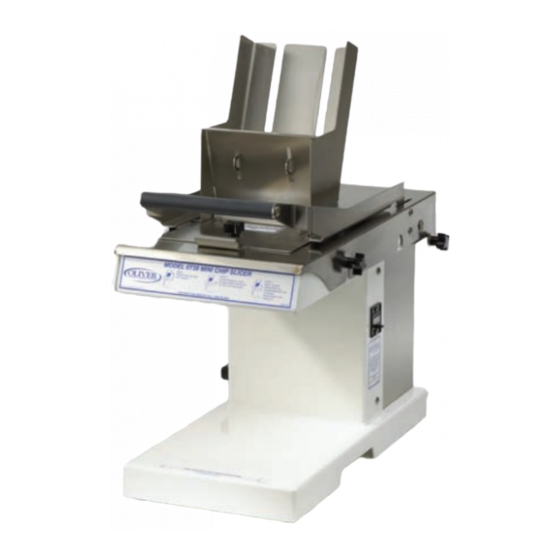
- Page 1 Walker, Michigan, U.S.A. 49534 USER’S OPERATING AND INSTRUCTION MANUAL MODEL 738-V MINI CHIP SLICER 0738S20000-CV...
-
Page 2: Table Of Contents
INDEX Section Description Document No. Page No. SAFETY INSTRUCTIONS -------------------------------------- 0738S20002 --------------------------- 1-1 DESCRIPTION/SPECIFICATIONS --------------------------- 0738S20025---------------------------- 2-1 INSTALLATION INSTRUCTIONS ---------------------------- 0738S20004 --------------------------- 3-1 OPERATING INSTRUCTIONS -------------------------------- 0738S20026 --------------------------- 4-1 TROUBLESHOOTING ------------------------------------------- 0758S20006 --------------------------- 5-1 CLEANING AND MAINTENANCE -----------------------------0758S20031 --------------------------- 6-1 Removing the Blade Frames --------------------------------------------------------------------------- 6-4 Cleaning ---------------------------------------------------------------------------------------------------- 6-5 Replacing the Blade Frames --------------------------------------------------------------------------- 6-5... - Page 3 THIS PAGE WAS INTENTIONALLY LEFT BLANK. GEN020319...
-
Page 4: Safety Instructions
SAFETY INSTRUCTIONS WARNING VARIOUS SAFETY DEVICES AND METHODS OF GUARDING HAVE BEEN PROVIDED ON THIS MACHINE. IT IS ESSENTIAL HOWEVER THAT THE MACHINE OPERATORS AND MAINTENANCE PERSONNEL OBSERVE THE FOLLOWING SAFETY PRECAUTIONS. IMPROPER INSTALLATION, MAINTENANCE, OR OPERATION OF THIS EQUIPMENT COULD CAUSE SERIOUS INJURY OR DEATH. 1. -
Page 5: Description/Specifications
Designed with reciprocating blade technology, the Mini Chip Slicer easily slices through day-old bagels and baguettes. The Model 738-V Mini Chip Slicer is constructed of stainless and painted steel. Easy to clean, the Mini Chip Slicer food contact surfaces - infeed cover, pusher, handle, and blade cartridge - can be removed without the use of tools for cleaning and sanitizing in a dishwasher. - Page 6 Product Capacities: Length 6 inches Width 6 inches Height 2 inches Standard Electrical Options: (Others consult factory) 1 phase, 60 Hz, 120VAC, 2 Amps. Shipping Weight: 100 lbs. (approximate) Net Weight: 80 lbs. (approximate) 0738S20025...
-
Page 7: Installation Instructions
INSTALLATION INSTRUCTIONS Before starting the Installation process make sure you observe the following caution notes. CAUTION THE SLICER IS HEAVY, USE PROPER TECHNIQUE WHEN LIFTING OR MOVING. Select a location for your slicer which has a substantial mounting surface and which has electrical service compatible with the load the machine will place on it as indicated on the electrical data plate of the machine. -
Page 8: Operating Instructions
OPERATING INSTRUCTIONS WARNING ALWAYS USE CARE WHENEVER WORKING NEAR THE CUTTING KNIVES. To operate the slicer, follow these simple steps: 1. Power unit on and lift the handle. The unit will automatically shut off. 2. Place the product atop the blades and so that the product is resting against the back of the chute. - Page 9 THIS PAGE WAS INTENTIONALLY LEFT BLANK. GEN020319...
-
Page 10: Troubleshooting
TROUBLE SHOOTING WARNING ALWAYS DISCONNECT THE SLICER FROM THE POWER SUPPLY BEFORE ATTEMPTING ANY TYPE OF MAINTENANCE TASK, INCLUDING TROUBLESHOOTING. Slicer will not start • The machine is not plugged in. • There is no power at the outlet. • The cover is not on correctly. -
Page 11: Cleaning And Maintenance
CLEANING AND MAINTENANCE WARNING ALWAYS UNPLUG THE SLICER BEFORE PERFORMING ANY TYPE OF MAINTENANCE TASK. To prepare your unit for cleaning please refer to the pictorial below for step by step instructions. 1. Remove the thumb screw atop of the front guard and remove the guard. Once the guard is removed use a mild cleaning solution on all surfaces to remove any residue or crumb build up (FIG A). - Page 12 WARNING NOW THAT THE FRONT GUARD HAS BEEN REMOVED, THE SLICING BLADES WILL BE EXPOSED. USE CAUTION WHEN MOVING ON TO THE NEXT STEP. 2. With the handle in the up position, insert the quick pin through the slot in the chute into the hole on the slide block.
- Page 13 4. Place the safety cover on the blade cartridge by first hooking it around the pin plate on the rear of the cartridge (FIG A). Now proceed to lay the cover down and fasten it with the screw provided on the cover (FIG B). Remove the (4) post hold down blocks and set aside (FIG C).
- Page 14 NOTE: Now that the safety cover has been placed this is a good time to brush crumbs from the blades. Using the brush provided, gently brush between the blades from the underside of the slicing area. WARNING ONLY CLEAN THE SLICING BLADES FROM THE BOTTOM. CLEANING THEM FROM THE TOP WILL DAMAGE THE BRUSH AND POTENTIALLY CAUSE INJURY.
-
Page 15: Cleaning
CLEANING Now that the blade frames have been safely removed you can now proceed with removing any crumb deposits within the machine. A brush, compressed air, or a vacuum are helpful tools for this task. REPLACING THE BLADE CARTRIDGE 6. Make sure that the drive assembly is in the correct position as shown below. NOTE: The blade cartridge will only fit back into the machine with the drive assembly in the correct configuration below. -
Page 16: Changing The Blades
CHANGING THE BLADES Oliver Packaging and Equipment suggests that blades not be changed in the field due to the potential for injury. We offer a blade frame cartridge exchange program for when blades become dull. Please contact your dealer or the Oliver service department. - Page 17 12. Remove the safety cover from the blade cartridge by loosening the screw and unhooking it from the pin plate at the rear of the cartridge. NOTE: Make sure that when the safety cover is not in use that it has a designated area to be stored.
- Page 18 15. Now that the pusher has been attached to the slide block, grab the handle with your left hand and remove the quick pin by pulling on the ring (Fig A). The pin can then be placed in the hole on the flange atop the chute (Fig B). Figure A Figure B 16.
-
Page 19: Lubrication
ALWAYS DISCONNECT THE SLICER FROM THE POWER SUPPLY BEFORE ATTEMPTING ANY TYPE OF MAINTENANCE TASK. Oliver suggests a vegetable based aerosol product be used to gently coat the blades on occasion. Once a month put a drop of a food approved lubricant on the plastic slide blocks on the inside of the unit. - Page 20 THIS PAGE WAS INTENTIONALLY LEFT BLANK. GEN020319...
-
Page 21: Main Frame
MAIN FRAME 0738S20034... -
Page 22: Parts List
Washer-#10 Spring Lock Stainless 5851-9355 Bumper-Rubber w/ Screw 5902-0035 Block-Guide 0738-0003-1 Screw-10-24 x 3/8 Stainless Truss 5843-5384 Plate-Prop 0738-0005-1 Nut-1/4-20 Stainless Locking 5831-9087 Washer-1/4 Flat Stainless 5851-9304 *Items not shown FOR SERVICE PARTS CALL OLIVER PACKAGING & EQUIPMENT @ 800-253-3893 0738S20034... - Page 23 ELECTRICAL PARTS 0738S20020...
- Page 24 Bushing-Strain Relief 90° 5765-1010 Nut-PG-11 Plastic Lock 5766-7786 Counter-5 Digit Mini 5712-9080 Screw-6-32 x 1/4 Stainless Truss 5843-5360 Screw-6-32 x 3/8 Green Grounding 5841-9501 Washer-#6 Shake Proof Stainless 5851-9129 FOR SERVICE PARTS CALL OLIVER PACKAGING & EQUIPMENT @ 800-253-3893 0738S20020...
- Page 25 THIS PAGE WAS INTENTIONALLY LEFT BLANK. GEN020319...
-
Page 26: Drive Components
0738-0051 Screw-6-32 x 1 ¼ Stainless Pan 5843-5547 Replacements for 200 are ordered assembled with fasteners. Parts may not be substituted within the assembly other than those called out. FOR SERVICE PARTS CALL OLIVER PACKAGING & EQUIPMENT @ 800-253-3893 0738S20021... -
Page 27: Slice Parts/Covers
SLICE PARTS/COVERS 0738S20028 10-1... -
Page 28: Parts List
5902-0023 Bracket-RH Cover Attachment 0738-0055-0001 433** Bracket-LH Cover Attachment 0738-0055-0002 Plate-Discharge 0738-0072K *Item 301 is replaced fully assembled. Specify slice thickness when ordering. **LH not shown. REV. 6/4/13 FOR SERVICE PARTS CALL OLIVER PACKAGING & EQUIPMENT @ 800-253-3893 0738S20028 10-2... - Page 29 WIRING DIAGRAM 1-60-120 0738S20013 12-1...
- Page 30 WARRANTY PARTS Oliver Packaging & Equipment Company warrants that if any part of the equipment (other than a part not manufactured by Oliver Packaging & Equipment ) proves to be defective (as defined below) within one year after shipment, and if Buyer returns the defective part to Oliver Packaging & Equipment within one year, Freight Prepaid to Oliver Packaging &...
- Page 31 4. The service dealer will then complete an invoice and send it to the Parts and Service Department at Oliver Packaging & Equipment Company. 5. The Parts and Service Manager of Oliver Packaging and Equipment Company will review the invoice and returned parts, if applicable, and approve for payment.
- Page 32 This policy applies to all parts returned to the factory whether for warranted credit, replacement, repair or re-stocking. Oliver Packaging and Equipment Company requires that the customer obtain a Return Material Authorization (RMA) number before returning any part. This number should appear on the shipping label and inside the shipping carton as well.
Need help?
Do you have a question about the 738-V and is the answer not in the manual?
Questions and answers