
Subscribe to Our Youtube Channel
Related Manuals for Oliver 711


Summary of Contents for Oliver 711
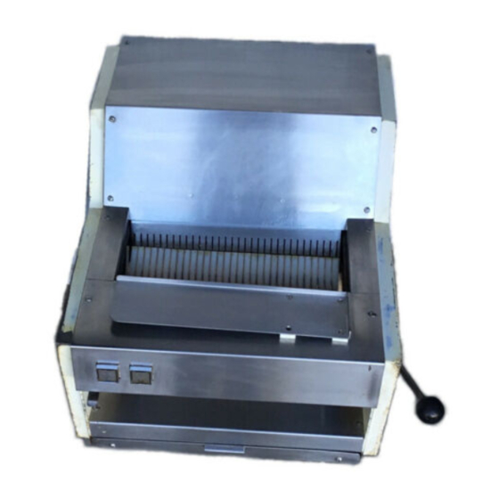
- Page 1 Grand Rapids, Michigan, U.S.A. 49504-5298 USER’S OPERATING AND INSTRUCTION MANUAL MODEL 711 COUNTER TOP SLICER 0711S20000CV...
- Page 2 MODEL 711 COUNTER TOP SLICER INDEX SAFETY INSTRUCTIONS................GEN861015 SLICER INSTALLATION................0711S20002 SLICER SPECIFICATIONS............... 0711S20003 OPERATION INSTRUCTIONS..............0711S20004 MAINTENANCE..................0711S20005 Removing Blade Frames ..............0711S20005-1 Replacing Blade Frames..............0711S20005-4 Changing The Blades................0711S20005-4 Tightening The Belt................0711S20005-6 Replacing The Belt................0711S20005-7 Replacing The Gas Spring..............
- Page 3 THIS PAGE WAS INTENTIONALLY LEFT BLANK. GEN020319...
-
Page 4: Safety Instructions
General Document SAFETY INSTRUCTIONS Various safety devices and methods of guarding have been provided on this machine. It is essential, however, that machine operators and maintenance personnel observe the following safety precautions. Improper installation or operation of this equipment may cause injury to personnel or damage to equipment. - Page 5 THIS PAGE WAS INTENTIONALLY LEFT BLANK. GEN020319...
-
Page 6: Slicer Installation
MODEL 711 COUNTER TOP SLICER SLICER INSTALLATION WARNING THE SLICER IS HEAVY. USE PROPER LIFTING TECHNIQUES, KEEP BACK STRAIGHT, KNEES BENT, AND LIFT WITH YOUR LEGS. USE GLOVES TO PROTECT YOUR HANDS CAUTION NEVER LIFT THE SLICER BY ITS SIDE COVERS. -
Page 7: Overall Machine Dimensions
MODEL 711 COUNTER TOP SLICER SLICER SPECIFICATIONS Physical specifications Net Weight: Approximately 255 pounds. Slice Spacings: Standard 3/8” (minimum), 7/16”, & 1/2” Others available (at extra cost), consult factory Product Capacities: Length 16” * Width 5-1/2” * Height 5-1/2” NOTE * Width and height dimensions are for a square product. - Page 8 MODEL 711 COUNTER TOP SLICER OPERATING INSTRUCTIONS WARNING ALWAYS USE CARE WHENEVER WORKING NEAR THE CUTTING KNIVES. To operate the machine, stand in front of the machine and grasp the lever with your right hand. Pull the lever all the way down and hold it in that position. Using your left hand load the product into the machine.
- Page 9 MODEL 711 COUNTER TOP SLICER OPERATING INSTRUCTIONS (Continued) When the slicing operation is complete, the machine will automatically stop. When this happens, remove the product from the cradle. Use of the standard bagging scoop will ease packaging of your product. See figure below.
-
Page 10: Maintenance
MODEL 711 COUNTER TOP SLICER MAINTENANCE WARNING ALWAYS UNPLUG THE SLICER BEFORE PERFORMING ANY TYPE OF MAINTENANCE TASK. REMOVING BLADE FRAMES Remove the top guard and front guard by removing the twelve slotted head screws which hold them in place. See the illustration on the next page. - Page 11 MODEL 711 COUNTER TOP SLICER REMOVING BLADE FRAMES (Continued) Use a wrench to loosen and remove the two capscrews which fasten the blade frame feet to the rocker shaft. See next illustration. CAUTION DO NOT LOOSEN THE FIXED COLLAR SOCKET SETSCREW Rev.
- Page 12 MODEL 711 COUNTER TOP SLICER REMOVING BLADE FRAMES (Continued) WARNING BLADES ARE EXTREMELY SHARP. ALWAYS HANDLE BLADE FRAMES WITH CARE Carefully lift the upper blade frame from the slicer. See the next illustration. NOTE Removal of the lower blade frame is not required to change its blades.
-
Page 13: Replacing Blade Frames
MODEL 711 COUNTER TOP SLICER REPLACING BLADE FRAMES To replace the blade frames, reverse the removal procedures. ensure that the feet of the blade frames rest snugly on the swing shafts. Tighten capscrews at the feet securely with a wrench. Top links must be attached to the blade frames with clips back in position. - Page 14 MODEL 711 COUNTER TOP SLICER CHANGING THE BLADES (Continued) The blades can be removed from the lower blade frame while it is still in the machine. This is done by using a second special blade changing tool. Insert the tool into the blade frame.
-
Page 15: Tightening The Belt
MODEL 711 COUNTER TOP SLICER TIGHTENING THE BELT CAUTION OVER-TIGHTENING THE DRIVE BELT MAY CAUSE BEARING OR MOTOR FAILURE. Remove the top guard and rear inspection plate from the slicer. See the next illustration. Locate the four motor mounting nuts and loosen slightly using a wrench. -
Page 16: Replacing The Belt
MODEL 711 COUNTER TOP SLICER REPLACING THE BELT Remove the top guard and rear inspection plate from the slicer, as described under “Tightening the Belt”. Loosen the motor mounting bolt nuts slightly (see Belt Tightening section), and lower the motor as far as it will go. Disconnect the end of the connecting rod at the rocker frame by removing the two capscrews and cap. - Page 17 MODEL 711 COUNTER TOP SLICER REPLACING THE GAS SPRING (Continued) WARNING THE GAS SPRING IS IN A COMPRESSED STATE, USE CARE WHEN REMOVING IF FROM THE MACHINE. To remove the gas spring, remove the push-on clip at the top of the gas spring by prying it off with a screwdriver.
- Page 18 MODEL 711 COUNTER TOP SLICER REPLACING THE GAS SPRING (Continued) To replace the gas spring, start by re-attaching the lower end of the spring with the shoulder screw. CAUTION USE A LOCKING FLUID, SUCH AS LOC-TITE TO PREVENT THE SCREW FROM LOOSENING BECAUSE OF VIBRATION.
- Page 19 MODEL 711 COUNTER TOP SLICER LUBRICATION Once a month put a drop of a food approved lubricant on the plastic links at the top of the blade frames. Also add a drop or two to each bushing on the pusher drive cross shaft and lever shaft.
- Page 20 MODEL 711 COUNTER TOP SLICER ADJUSTMENTS SLICES VARY IN THICKNESS Remove rear inspection plate from the slicer. With a wrench loosen, but do not remove, the hex head capscrews in the feet of each of the top and bottom blade frames.
- Page 21 MODEL 711 COUNTER TOP SLICER ADJUSTING THE GAS SPRING (Continued) The pin located in the high forward position should be used when greater force is desired as the product is first entering the knives. Using proper gas spring installation procedures, see “Replacing a Gas Spring”, in the maintenance section, compress the spring and mount it on the desired pin, secure it with a new clip.
-
Page 22: Troubleshooting Guide
MODEL 711 COUNTER TOP SLICER TROUBLE SHOOTING GUIDE WARNING ALWAYS UNPLUG THE SLICER WHEN ADJUSTING OR REPAIRING. PROBLEM PROBABLE CAUSES (S) REMEDY Bread slices vary in Blade frames are out of Adjust blade frames. thickness. adjustment. see "Adjustments" Blade frame are Not enough clearance Adjust eccentric pins. - Page 23 MODEL 711 COUNTER TOP SLICER TROUBLE SHOOTING GUIDE (Continued) PROBLEM PROBABLE CAUSES (S) REMEDY Switches are turned Motor or drive system is Repair or Replace ON, motor hums but binding. (Defective bearings.) will not start. Interference between parts Adjust or repair SEE CAUTION of the slicer mechanism.
-
Page 24: Recommended Spare Parts
MODEL 711 COUNTER TOP SLICER RECOMMENDED SPARE PARTS NOTE Parts listed below are for standard electrics (1-60-115/230) for other electrics consult Oliver Products Company. PART NUMBER DESCRIPTION NO. REQ'D 6084-8700 Gas Spring 5835-7705 Hairpin 0777-0034 Eccentric Pin 0732-0013 Blade Frame Pin... - Page 25 REV. 1-23-04 0711S20013...
-
Page 26: Mechanical Parts List
MODEL 711 COUNTER TOP SLICER MECHANICAL PARTS LIST NOTE Items not identified on these sheets or drawings are standard hardware items which may be purchased locally. OLIVE MANUFACTURER PART PART QTY. DESCRIPTION MANUFACTURE 0797-0049-103 Pulley Oliver Products Company 0797-0057-2 Stud... - Page 27 MODEL 711 COUNTER TOP SLICER MECHANICAL PARTS LIST (Continued) ITEM OLIVER MANUFACTURERS PART NUMBER PART NUMBER QTY. DESCRIPTION MANUFACTURER 5842-1802 Screw No Primary Mfg. 4655-0313-1401 Washer Oliver Products Company 5220-4040 204NPP Ball Bearing Fafnir (See #7) 5220-5040 205NPP Ball Bearing...
- Page 28 MODEL 711 COUNTER TOP SLICER MECHANICAL PARTS LIST (Continued) OLIVE MANUFACTURER PART PART QTY. DESCRIPTION MANUFACTURE 5842-8501 Shoulder No Primary Mfg. 5902-8790 225208 Spindle DE-STA-CO Division Dover Corporation Detroit, MI 48203 5911-7002 111-3/8- Knob Dimco-Gray Company Centerville, OH 45459 6084-8700...
- Page 29 MODEL 711 COUNTER TOP SLICER ELECTRICAL COMPONENTS 60/50 CY WIRING DIAGRAM 1-60/50-115/110 & 1-60/50-230/220 (Not for “Self Serve” machines) Rev. 1-19-99 0711S20009-...
- Page 30 MODEL 711 COUNTER TOP SLICER NOTE Items not identified on these sheets or drawings are standard hardware items which may be purchased locally. ELECTRICAL PARTS LIST (1/2 HP, 1-60-115) OLIVER MANUFACTURERS ITEM PART NUMBER PART NUMBER QTY. DESCRIPTION MANUFACTURER 0711-0027...
- Page 31 MODEL 711 COUNTER TOP SLICER ELECTRICAL PARTS LIST (1/2 HP, 1-60-230) ITEM OLIVER MANUFACTURERS PART NUMBER PART NUMBER QTY. DESCRIPTION MANUFACTURER 0711-0027 Cover Oliver Products Company 0711-0052 Switch-1LS Oliver Products Company 0711-0053 Switch-2LS Oliver Products Company 0711-0030 Nutbar Oliver Products Company...
- Page 32 MODEL 711 COUNTER TOP SLICER ELECTRICAL PARTS LIST (1/2 HP, 1-50-110) ITEM OLIVER MANUFACTURERS PART NUMBER PART NUMBER QTY. DESCRIPTION MANUFACTURER 0711-0027 Cover Oliver Products Company 0711-0052 Switch-1LS Oliver Products Company 0711-0053 Switch-2LS Oliver Products Company 0711-0030 Nutbar Oliver Products Company...
- Page 33 MODEL 711 COUNTER TOP SLICER ELECTRICAL PARTS LIST (1/2 HP, 1-50-220) ITEM OLIVER MANUFACTURERS PART NUMBER PART NUMBER QTY. DESCRIPTION MANUFACTURER 0711-0027 Cover Oliver Products Company 0711-0052 Switch-1LS Oliver Products Company 0711-0053 Switch-2LS Oliver Products Company 0711-0030 Nutbar Oliver Products Company...
-
Page 34: Part Description
MODEL 711 COUNTER TOP BREAD SLICER PARTS LIST FOR SELF SERVE OPTION ITEM NO. PART DESCRIPTION PART NO. *153 Holddown Assy 0711-0078-1XX Proximity Switch 0711-0070 Nutbar 0711-0073 Door Hinge 0711-0066 Door 0711-0067 0711-0068 *304 Gas Spring Pin 0711-0069 Latch Plate... - Page 35 MODEL 711 COUNTER TOP BREAD SLICER WIRING DIAGRAM 1-60/50-115/110 & 1-60/50-230/220 “SELF SERVE” 0711S20011-...
-
Page 36: Warranty
Oliver) proves to be defective (as defined below) within one year after shipment, and if Buyer returns the defective part to Oliver within one year, Freight Prepaid to Oliver’s plant in Grand Rapids, MI, then Oliver, shall, at Oliver’s option, either repair or replace the defective part, at Oliver’s expense. -
Page 37: Warranty Procedure
4. The service dealer will then complete an invoice and send it to the Customer Service Department at Oliver Products Company. 5. The Customer Service Manager of Oliver Products Company will review the invoice and returned parts, if applicable, and approve for payment. -
Page 38: Returned Parts Policy
This policy applies to all parts returned to the factory whether for warranted credit, replacement, repair or re-stocking. Oliver Products Company requires that the customer obtain a Return Material Authorization (RMA) number before returning any part. This number should appear on the shipping label and inside the shipping carton as well.
Need help?
Do you have a question about the 711 and is the answer not in the manual?
Questions and answers