
Subscribe to Our Youtube Channel
Related Manuals for Oliver 758-N


Summary of Contents for Oliver 758-N
- Page 1 Grand Rapids, Michigan, U.S.A. 49504-5298 USER’S OPERATING AND INSTRUCTION MANUAL MODEL 758-N FRONT LOAD DUO-SLICER 0758S20000-CV...
-
Page 2: Table Of Contents
758-N Front Load Dual-Slicer INDEX Section Description Document No. Page No. SAFETY INSTRUCTIONS -------------------------------------- 0758S20002 --------------------------- 1-1 DESCRIPTION/SPECIFICATIONS --------------------------- 0758S20003---------------------------- 2-1 Description -------------------------------------------------------------------------------------------------- 2-1 Specifications----------------------------------------------------------------------------------------------- 2-1 INSTALLATION INSTRUCTIONS ---------------------------- 0758S20004 --------------------------- 3-1 Slicer Installation ------------------------------------------------------------------------------------------ 3-1 OPERATING INSTRUCTIONS -------------------------------- 0758S20005 --------------------------- 4-1... - Page 3 758-N Front Load Dual-Slicer INDEX (Continued) REPLACEMENT PARTS SECTION (Continued) Section Description Document No. Page No. COVERS ------------------------------------------------------------ 0758S20010 --------------------------- 9-1 Drawing ------------------------------------------------------------------------------------------------ 9-1 Parts List ----------------------------------------------------------------------------------------------- 9-2 PUSHER ------------------------------------------------------------ 0758S20011 -------------------------- 10-1 Drawing ----------------------------------------------------------------------------------------------- 10-1 Parts List ---------------------------------------------------------------------------------------------- 10-2...
-
Page 4: Safety Instructions
758-N Front Load Dual-Slicer SAFETY INSTRUCTIONS WARNING VARIOUS SAFETY DEVICES AND METHODS OF GUARDING HAVE BEEN PROVIDED ON THIS MACHINE. IT IS ESSENTIAL HOWEVER THAT THE MACHINE OPERATORS AND MAINTENANCE PERSONNEL OBSERVE THE FOLLOWING SAFETY PRECAUTIONS. IMPROPER INSTALLATION, MAINTENANCE, OR OPERATION OF THIS EQUIPMENT COULD CAUSE SERIOUS INJURY OR DEATH. -
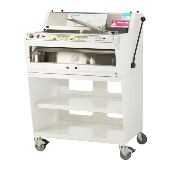
Page 5: Description/Specifications
DESCRIPTION/SPECIFICATIONS Description The Oliver Model 758-N Front Load Duo Slicer is of a compact, sturdy, time tested design, based off of a model which has been used in bakeries worldwide for many years. The machine is easy to operate and can be loaded and unloaded from the front of the machine. - Page 6 758-N Front Load Dual-Slicer Product Capacities: Length 13 inches per side (See Note) Width 5-1/2 inches (See Note) Height 5-1/2 inches (See Note) NOTE WIDTH AND HEIGHT DIMENSIONS ARE FOR A SQUARE PRODUCT. LOWER AND WIDER PRODUCTS MAY ALSO BE SLICED BY TAKING CARE IN LOADING THE PRODUCT.
-
Page 7: Installation Instructions
758-N Front Load Dual-Slicer INSTALLATION INSTRUCTIONS Slicer Installation: Before starting the Installation process make sure you observe the following caution notes. CAUTION THE SLICER IS HEAVY, USE PROPER TECHNIQUE WHEN LIFTING OR MOVING. CAUTION NEVER LIFT THE SLICER BY ITS SIDE COVERS. -
Page 8: Operating Instructions
758-N Front Load Dual-Slicer OPERATING INSTRUCTIONS (Shown using single slice thickness unit) WARNING ALWAYS USE CARE WHENEVER WORKING NEAR THE CUTTING KNIVES. To operate the slicer, stand in front of the machine and grasp the lever with your right hand. Pull the lever all the way down and hold it in that position. Using your left hand load the product into the machine. - Page 9 758-N Front Load Dual-Slicer CAUTION NEVER PUSH THE HAND LEVER. Operating Instructions (Continued) When the slicing operation is complete the machine will automatically stop. Once stopped, remove the product from the cradle. Use of the standard front mounted bagging scoop will ease packaging of your product.
-
Page 10: Troubleshooting
758-N Front Load Dual-Slicer TROUBLE SHOOTING WARNING ALWAYS DISCONNECT THE SLICER FROM THE POWER SUPPLY BEFORE ATTEMPTING ANY TYPE OF MAINTENANCE TASK, INCLUDING TROUBLESHOOTING. The Slicer Will Not Start (Motor Is Not Humming) • The machine is not plugged in. -
Page 11: The Slicer Will Not Start (Motor Is Humming)
758-N Front Load Dual-Slicer Trouble Shooting (Continued) The Slicer Will Not Start (Motor Is Humming) CAUTION DO NOT ALLOW THE MOTOR TO HUM WITHOUT STARTING. OVERHEATING CAN PERMANENTLY DAMAGE THE MOTOR. NOTE A SPECIAL NON-VENTILATED MOTOR MUST BE USED WITH THIS SLICER. -
Page 12: Bread Slices Vary In Thickness
758-N Front Load Dual-Slicer Trouble Shooting (Continued) Bread Slices Vary in Thickness • The blade frames are out of adjustment. (See the “Maintenance” section of this manual under “Adjusting the Blade Frames When Slices Vary in Thickness” on how to correct this problem.) The Blade Frames Are Knocking •... -
Page 13: The Bread Is Cutting Slowly Or Is Being Damaged
758-N Front Load Dual-Slicer Trouble Shooting (Continued) The Bread is Cutting Slowly or is Being Damaged • The product you are attempting to slice is below the minimum height capacity of the machine. • You are pushing the lever of the machine in an attempt to speed slicing. This may not only damage the product but may also damage the machine. -
Page 14: Maintenance
758-N Front Load Dual-Slicer MAINTENANCE Removing The Blade Frames (Shown using single slice thickness unit) WARNING ALWAYS UNPLUG THE SLICER BEFORE PERFORMING ANY TYPE OF MAINTENANCE TASK. Remove the bagging scoop, the top and front covers by removing the ten knobs which secure them. - Page 15 758-N Front Load Dual-Slicer Removing The Blade Frames (Continued) NOTE DO NOT LOOSEN THE NUTS WHICH SECURE THE ECCENTRIC PINS. Pull the clip from the eccentric pin and slide the link toward the eccentric pin mounting plate. See the illustration below.
- Page 16 758-N Front Load Dual-Slicer Removing The Blade Frames (Continued) WARNING BLADES ARE EXTREMELY SHARP ALWAYS HANDLE BLADE FRAMES WITH CARE. Carefully lift the upper blade frame from the slicer. NOTE REMOVAL OF THE LOWE BLADE FRAME IS NOT REQUIRED TO CHANGE ITS BLADES...
-
Page 17: Replacing The Blade Frames
758-N Front Load Dual-Slicer Replacing The Blade Frames WARNING ALWAYS DISCONNECT THE SLICER FROM THE POWER SUPPLY BEFORE ATTEMPTING ANY TYPE OF MAINTENANCE TASK. Replacement of the blade frames is done by reversing the removal procedures. Ensure that the feet of the blade frames rest snuggly on the swing shafts and that you have included the Belleville washers with the eye bolts. -
Page 18: Changing The Blades
758-N Front Load Dual-Slicer Changing The Blades WARNING ALWAYS DISCONNECT THE SLICER FROM THE POWER SUPPLY BEFORE ATTEMPTING ANY TYPE OF MAINTENANCE TASK. WARNING BLADES ARE EXTREMELY SHARP ALWAYS HANDLE WITH CARE. NOTE WHEN REPLACING ALL THE BLADES, ALWAYS REMOVE AND REPLACE ONE BLADE AT A TIME. - Page 19 758-N Front Load Dual-Slicer Changing The Blades (Continued) The new knife can be installed in the upper blade frame by reversing the removal procedure. A paper clip can be used to hold the knife in position on the lower pin to ease installation.
-
Page 20: Tightening The Belt
758-N Front Load Dual-Slicer Tightening the Belt (Shown using single slice thickness unit) WARNING ALWAYS DISCONNECT THE SLICER FROM THE POWER SUPPLY BEFORE ATTEMPTING ANY TYPE OF MAINTENANCE TASK. CAUTION OVER-TIGHTENING THE DRIVE BELT MAY CAUSE BEARING OR MOTOR FAILURE. -
Page 21: Replacing The Belt
758-N Front Load Dual-Slicer Replacing the Belt (Shown using single slice thickness unit) WARNING ALWAYS DISCONNECT THE SLICER FROM THE POWER SUPPLY BEFORE ATTEMPTING ANY TYPE OF MAINTENANCE TASK. Remove the top cover by removing the six knobs which secure it. Using a wrench, loosen but do not remove the four nuts which secure the motor mounting plate to the machine. -
Page 22: Replacing The Gas Spring
758-N Front Load Dual-Slicer Replacing The Gas Spring (Shown using single slice thickness unit) WARNING ALWAYS DISCONNECT THE SLICER FROM THE POWER SUPPLY BEFORE ATTEMPTING ANY TYPE OF MAINTENANCE TASK. The Gas Spring is located on the right hand side of the machine, therefore the right hand cover must be removed. - Page 23 758-N Front Load Dual-Slicer Replacing the Gas Spring (Continued) WARNING THE GAS SPRING IS IN A COMPRESSED STATE, USE CARE WHEN REMOVING IT FROM THE MACHINE. To remove the gas spring, remove the push-on clip at the top of the gas spring by prying it off with a screw driver.
- Page 24 758-N Front Load Dual-Slicer Replacing the Gas Spring (Continued) Using two people, grasp the spring as shown in the next illustration and slide the gas spring over the same upper pin that the old gas spring was removed from. See the caution statement below.
-
Page 25: Adjusting The Gas Spring
758-N Front Load Dual-Slicer Adjusting The Gas Spring WARNING ALWAYS DISCONNECT THE SLICER FROM THE POWER SUPPLY BEFORE ATTEMPTING ANY TYPE OF MAINTENANCE TASK. CAUTION FREQUENT ADJUSTMENT OF THE GAS SPRING IS NOT RECOMMENDED. The gas spring must be removed and relocated to adjust its force. To remove the gas spring, see “Replacing the Gas Spring”... -
Page 26: Adjusting The Blade Frames When Slices Vary In Thickness
758-N Front Load Dual-Slicer Adjusting The Blade Frames When Slices Vary In Thickness (Shown using single slice thickness unit) WARNING ALWAYS DISCONNECT THE SLICER FROM THE POWER SUPPLY BEFORE ATTEMPTING ANY TYPE OF MAINTENANCE TASK. Assuming that the lower blade frame has been installed and centered in the machine, meaning that it has been aligned with the slots in the top cover and holddown, and secured with the locking cams, proceed as follows to adjust the upper blade frame. -
Page 27: Adjusting The Clearance Between The Blade Frames
758-N Front Load Dual-Slicer Adjusting The Clearance Between The Blade Frames (Shown using single slice thickness unit) WARNING ALWAYS DISCONNECT THE SLICER FROM THE POWER SUPPLY BEFORE ATTEMPTING ANY TYPE OF MAINTENANCE TASK. Start by removing the bagging scoop and the top and front covers by removing their knobs. -
Page 28: Lubrication
758-N Front Load Dual-Slicer Lubrication WARNING ALWAYS DISCONNECT THE SLICER FROM THE POWER SUPPLY BEFORE ATTEMPTING ANY TYPE OF MAINTENANCE TASK. Once a month put a drop of a food approved lubricant on the plastic links at the top of the blade frames. -
Page 29: Recommended Spare Parts
0797-0029-1 Knife-Type A As Req’d. 0777-0970 Bolt-Eye 0777-0971 Cam-Clamp 5852-0050 Spring-Bellville 6084-8700 Gas Spring 5831-8225 Clip-Push On 5251-0030 Bearing-5/8 Cam Follower 5251-0091 Bearing-3/4 Cam Follower *For Other Electrics Contact the Factory For Service Parts Call Oliver Products @ 800-253-3893 0758S20008... - Page 30 THIS PAGE WAS INTENTIONALLY LEFT BLANK. GEN020319...
- Page 31 758-N Front Load Dual-Slicer MAIN FRAME Rev. 8-23-10 0758S20009...
- Page 32 Knob W/Stud M5 x .8 x 15mm LG 5911-7210 Pin-Eccentric 0730-0031 Link-Blade Frame 0711-0002 Clip-Hairpin 5835-7705 Plate-Divider 0758-0030 Guide-RH Outside Loaf 0758-0031-0001 Guide-LH Outside Loaf 0758-0031-0002 Screw-M3.5 x .6 x 10 mm Stainless Flat 8843-2511 FOR SERVICE PARTS CALL OLIVER PRODUCTS @ 800-253-3893 Rev. 8-23-10 0758S20009...
-
Page 33: Covers
758-N Front Load Dual-Slicer COVERS 0758S20010... - Page 34 Knob-Clamp W/Stud M5 x .8 x 15MM LG 5911-7210 Scoop-Bread 0711-0004-1 Stop-Bread 0711-0080 Knob-Clamp W/Stud M6 x 1 4560-2507-18 Washer-Flat Nylon 5851-8120 Tray-Crumb 0758-0011 Cover-RH Side 0732-0006 Cover-LH Side 0732-0007 Cover-Electrical Box 0732-0008 Cover-Switch Enclosure 0732-0009 FOR SERVICE PARTS CALL OLIVER PRODUCTS @ 800-253-3893 0758S20010...
-
Page 35: Pusher
758-N Front Load Dual-Slicer PUSHER 0758S20011 10-1... - Page 36 Bearing-5/8 Dia. Cam Follower 5251-0030 Guide-RH Pusher 0711-0051-0001 Guide-LH Pusher 0711-0051-0002 Hub-Pusher Drive 0732-0023 Bearing-3/4 Dia. Cam Follower 5251-0091 Bearing-Bronze Flange 5254-3139 Lever-Duo Extended Pusher 0758-0018 Knob-Ball 5911-7120 * Item not shown FOR SERVICE PARTS CALL OLIVER PRODUCTS @ 800-253-3893 0758S20011 10-2...
-
Page 37: Rocker
758-N Front Load Dual-Slicer ROCKER 0758S20012 11-1... - Page 38 ITEM NO PART DESCRIPTION PART NUMBER Frame-Rocker 0758-0002 Bearing-Ball 5220-4040 Ring-Retaining 5840-1036 Shaft-Swing 0758-0003 Bearing-Ball w/ Snap Ring 5220-0042 Collar-Locating 0758-0004 Collar-Hold Down 0758-0005 Rod-Nylon Threaded 3/8-16 5840-8076 Cap-Clamp 0730-0023 FOR SERVICE PARTS CALL OLIVER PRODUCTS @ 800-253-3893 0758S20012 11-2...
-
Page 39: Driven Pulley
758-N Front Load Dual-Slicer DRIVEN PULLEY 0758S20013 12-1... - Page 40 PART NUMBER Pulley-Driven 0730-0005-001 Stud 0797-0058-019 Stud-Swing 0797-0057-219 Rod Assembly W/Bearings 0797-0071-4 Ring-Retaining 5840-2825 Bearing-Ball 5220-5040 Ring-Retaining 5840-1040 Washer-Flat M10 8851-8418 Washer-Spring Lock M10 8851-9418 Screw-Hex HD M10 X 20MM 8842-0583 FOR SERVICE PARTS CALL OLIVER PRODUCTS @ 800-253-3893 0758S20013 12-2...
-
Page 41: Slice Parts
758-N Front Load Dual-Slicer SLICE PARTS 0758S20014 13-1... - Page 42 Cradle-1/2” Slice 0758-0014-032 516* Cradel-3/4” Slice 0758-0014-048 Knob-Knurled 5911-7218 Spacer-Cradle 0758-0009 519* Cover-Top 0758-0016-xxxx Knob W/Stud M5 x .8 x 15mm Lg. 5911-7210 * Specify Slice Thickness ** Item Not Shown FOR SERVICE PARTS CALL OLIVER PRODUCTS @ 800-253-3893 0758S20014 13-2...
- Page 43 758-N Front Load Dual-Slicer ELECTRICAL PARTS 0758S20015 14-1...
- Page 44 Nutbar-Switch Mounting 0732-0020 Bushing-Strain Relief 5765-1110 Relay-Power 1-50/60-110/115 5749-8027 Relay-Power 1-50/60-220/230 5749-8028 Block-Terminal 5770-7451 Strip-Marker 5770-7328 Plug-Hole 5769-3008 Green Grounding Screw 6-32 3/8” 5841-9501 For other Electrics Consult the Factory Continued FOR SERVICE PARTS CALL OLIVER PRODUCTS @ 800-253-3893 0758S20015 14-2...
-
Page 45: Electrical
Cord Power 1-60-115 0711-0056 832* Cord Power 1-60-230 & 1-50-110/220 0711-0056-001 Harness-Wire 0711-0057 Plug-Hole 5769-3008 839* Nameplate-Wiring Diagram (Single Phase) 6402-3103 Plug-Power 1-60-230 5765-2030 Plug-Hole 5769-3013 For other Electrics Consult the Factory FOR SERVICE PARTS CALL OLIVER PRODUCTS @ 800-253-3893 0758S20015 14-3... -
Page 46: Stand
758-N Front Load Dual-Slicer STAND STAND PARTS LIST ITEM NO PART DESCRIPTION PART NUMBER Stand-26” Painted Steel 0758-0013 Caster-Swivel 4” w/o Brake (NSF) 5902-2420 Caster-Swivel 4” w/Brake (NSF) 5902-2421 FOR SERVICE PARTS CALL OLIVER PRODUCTS @ 800-253-3893 0758S20016 15-1... - Page 47 THIS PAGE WAS INTENTIONALLY LEFT BLANK. GEN020319...
-
Page 48: Wiring Diagram 1-60-115/230
758-N Front Load Dual-Slicer WIRING DIAGRAM 1-60-115/230 & 1-50-110/220 For other Electrics Consult the Factory 0758S20017 15-1... -
Page 49: Warranty
WARRANTY PARTS Oliver Packaging & Equipment Company warrants that if any part of the equipment (other than a part not manufactured by Oliver Packaging & Equipment ) proves to be defective (as defined below) within one year after shipment, and if Buyer returns the defective part to Oliver Packaging & Equipment within one year, Freight Prepaid to Oliver Packaging &... -
Page 50: Warranty Procedure
4. The service dealer will then complete an invoice and send it to the Parts and Service Department at Oliver Packaging & Equipment Company. 5. The Parts and Service Manager of Oliver Packaging and Equipment Company will review the invoice and returned parts, if applicable, and approve for payment. -
Page 51: Returned Parts Policy
This policy applies to all parts returned to the factory whether for warranted credit, replacement, repair or re-stocking. Oliver Packaging and Equipment Company requires that the customer obtain a Return Material Authorization (RMA) number before returning any part. This number should appear on the shipping label and inside the shipping carton as well.
Need help?
Do you have a question about the 758-N and is the answer not in the manual?
Questions and answers