Table of Contents
Advertisement
Quick Links
Parts
INSTRUCTIONS–PARTS LIST
Contents
INSTRUCTIONS
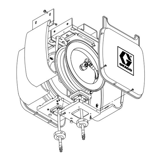
Series 250 Hose Reels
See pages 7 through 9 for Hose Reel part numbers,
descriptions, and maximum working pressure
information.
These hose reels are designed to
dispense lube products, air, water,
transmission fluid, antifreeze, and
windshield washer solvent only. Any
other use of these hose reels can
cause unsafe operating conditions and
result in component rupture, fire, or
explosion, which could cause serious
bodily injury, including fluid injection.
NOTES:
D These hose reels are for stationary
mountings only.
D 250 Series Hose Reels are direct
replacements for 200 Series
Hose Reels.
This manual contains important
warnings and information.
READ AND KEEP FOR REFERENCE.
WARNING
GRACO INC. P.O. BOX 1441 MINNEAPOLIS, MN 55440–1441
ECOPYRIGHT 1998, GRACO INC.
Graco Inc. is registered to I.S. EN ISO 9001
308899
First choice when
quality counts.t
Rev. D
1638A
Advertisement
Table of Contents

Related Manuals for Graco 250 Series


Summary of Contents for Graco 250 Series
- Page 1 D These hose reels are for stationary mountings only. D 250 Series Hose Reels are direct replacements for 200 Series Hose Reels. 1638A GRACO INC. P.O. BOX 1441 MINNEAPOLIS, MN 55440–1441 ECOPYRIGHT 1998, GRACO INC. Graco Inc. is registered to I.S. EN ISO 9001...
-
Page 2: Table Of Contents
............... Graco Standard Warranty . - Page 3 Notes 308899...
-
Page 4: Warnings
D Read all instruction manuals, tags, and labels before operating the equipment. D Use the equipment only for its intended purpose. If you are not sure, call your Graco distributor. D Do not alter or modify this equipment. Use only genuine Graco parts and accessories. Use only extensions that are designed for use with your dispensing valve. - Page 5 WARNING INJECTION HAZARD Fluid from the dispensing valve, leaks, or ruptured components can inject fluid into your body and cause extremely serious injury, including the need for amputation. Fluid splashed in the eyes or on the skin can also cause serious injury. D Fluid injected into the skin might look like a minor cut, but it is a serious injury.
- Page 6 WARNING FIRE AND EXPLOSION HAZARD Improper grounding, poor ventilation, open flames, or sparks can cause a hazardous condition and result in a fire or explosion and serious injury. D Be sure the entire fluid system is properly grounded. The hoses supplied with these hose reels are electrically conductive.
-
Page 7: Hose Reels And Reel Assemblies
Hose Reels and Reel Assemblies Bare Hose Reels Open Hose Reel Dispensing Assemblies One of these bare reels is used in each reel assembly These assemblies include a basic hose reel assembly in this manual. Bare reels do not include hoses, and a dispensing valve option. -
Page 8: Table Of Series 250 Open Hose Reels
Table of Series 250 Open Hose Reels Hose reel assemblies with parts breakdowns in this instruction manual have their page numbers listed in the Model No. column of this table. Type Maximum Dispensing Working Hose Service or Control Valve Meter Pressure Model No. -
Page 9: Table Of Series 250 Enclosed Hose Reels
Table of Series 250 Enclosed Hose Reels These enclosed hose reel assemblies include Side Enclosure Kit 218546 (shown on page 28). For each bank of reels, order one End Enclosure Kit 218548 (also shown on page 28). Type Maximum Dispensing or Working Hose Service... -
Page 10: Installation
Installation CAUTION Be sure the mounting surface is strong enough to support the reels, the weight of the lubricants, and the stress caused by hard pulls on the service hoses. See page 33 for the dry weights of the hose reel assemblies. Mounting the Hose Reel(s) 1. - Page 11 Installation 6. Adjust the spring tension of the reel. Hose Reels shipped with hoses come from the 7. Install the hose stop (45) and dispensing factory with the tension pre-set for a typical valve. Position the hose stop so the hose extends installation.
- Page 12 Installation Ceiling Mounting Directly to an I-Beam 3. Slide the hose reel onto the base plate (304). Install the hold-down plate (302) and capscrew The reel base has slots (A) to allow two screws to be (301). Tighten the screw firmly. See Fig. 7. started before mounting the reel to the support.
- Page 13 Installation Adjusting Spring Tension 3. Check the spring tension; the hose must pull out WARNING fully and retract fully. Wrap or unwrap more loops, one at a time, until the spring has the desired Always wear heavy gloves when you adjust the tension.
- Page 14 Installation Installing the Hose Reel Enclosures 2. For more than one reel, bolt the caps together as shown. (See Fig. 9.) 3. Noting the correct position, secure the black trim NOTE: Enclosed hose reels are supplied only with plate (108) to the side panel (101) using the side enclosures.
- Page 15 Installation Installing a Hose on a Bare Reel 6. Pull the hose hard enough to release the latch, slowly allow the hose to retract until a few feet of 1. Locate the length and size of your hose in the hose sticks out through the rollers, and latch the chart below.
-
Page 16: Maintenance
Maintenance Pressure Relief Procedure Replacing the Service Hose 1. Relieve the pressure. WARNING WARNING INJECTION HAZARD To reduce the risk of serious injury, including fluid injection, splashing in the INJECTION HAZARD eyes or on the skin, or injury from mov- To reduce the risk of serious injury ing parts, always follow this procedure whenever whenever you are instructed to relieve... - Page 17 Maintenance 4. Disconnect and remove the hose. 5. Attach the new hose (48) to the hose reel swivel (34), and carefully remove the C-clamp. See Fig. 13. 6. Pull the hose hard enough to release the latch, and slowly allow the hose to retract. 7.
-
Page 18: Service
Service Swivel 1. Relieve the pressure. 2. Disassemble the parts as shown in Fig. 14 or Fig. 15, depending on your hose reel model. Clean the parts, and inspect them for wear or WARNING damage. INJECTION HAZARD 3. Grease the new parts, and lubricate the cavity of To reduce the risk of serious injury the swivel assembly (34) with high-quality grease. - Page 19 Service Reel Spring 1. Relieve the pressure, and disconnect the inlet hose from the reel. WARNING INJECTION HAZARD To reduce the risk of serious injury whenever you are instructed to relieve pressure, always follow the Pressure Relief Procedure on page 16. 2.
- Page 20 Service 12. Before you continue with this procedure, read the Warning below. WARNING Use extreme caution when handling the spring. The spring (25), which is located behind the flange (26), is always under great tension and could be propelled from the lower flange with enough force to cause serious injury.
- Page 21 Service Latch CAUTION If the reel latch malfunctions or becomes sluggish, To ensure proper spring operation, the spring and disassemble the latching mechanism. See Fig. 20. reel hub must be installed with the inside end of Clean and lubricate or replace the broken or worn the spring hooked into the reel hub (41) and the components as necessary.
-
Page 22: Parts Drawings And Lists Low-Pressure Hose Reels, Model No. 240956 Through 240969
Parts Drawing — Low Pressure 48, 49, or 50 Ref 48, 49, 50 8616B 0.030” maximum 03715A clearance Use one washer (21) here. Detail for Placement of Washers (21) Add washers here (at least one) to achieve 0.030” maximum clearance. 308899... - Page 23 Parts List — Low Pressure Model 240956, Series A Hose reel with 25 ft (7.6 m), 180 psi (1.2 MPa, 12 bar) hose Includes items 4 to 48 and 51 Model 240957, Series A Bare hose reel, 1800 psi (12 MPa, 124 bar) maximum working pressure Includes items 4 to 41 Model 240958, Series A Hose reel with 40 ft (12.2 m), 180 psi (1.2 MPa, 12 bar) hose...
-
Page 24: Medium-Pressure Hose Reels, Model No. 240961 Through 240963
Parts Drawing — Medium Pressure 48 or 49 Ref 48, 49 0.030” maximum 8616B 03715A clearance Use one washer (21) here. Detail for Placement of Washers (21) Add washers here (at least one) to achieve 0.030” maximum clearance. 308899... - Page 25 Parts List — Medium Pressure Model 240961, Series A Bare hose reel, 1800 psi (12 MPa, 124 bar) maximum working pressure Includes items 4 to 41 Model 240962, Series A Hose reel with 16 ft (4.9 m), 1800 psi (12 MPa, 124 bar) hose Includes items 4 to 48, 50, and 51 Model 240963, Series A Hose reel with 25 ft (7.6 m), 1800 psi (12 MPa, 124 bar) hose...
-
Page 26: High-Pressure Hose Reels, Model No. 240965 Through 240967
Parts Drawing — High Pressure 48 or 49 Ref 48, 49 8617B 0.030” maximum 03713A clearance Use one washer (21) here. Detail for placement of washers (21) Add washers here (at least one) to achieve 0.030” maximum clearance. 308899... - Page 27 Parts List — High Pressure Model 240965, Series A Bare hose reel, 8000 psi (55 MPa, 552 bar) maximum working pressure Includes 4 to 46 Model 240966, Series A Hose reel with 20 ft (6.1 m), 5000 psi (34 MPa, 345 bar) hose Includes 4 to 48 and 50 Model 240967, Series A Hose reel with 35 ft (10.7 m), 5000 psi (34 MPa, 345 bar) hose...
-
Page 28: Side Enclosure Kit 218546
Part No. Description Qty. 218367 PANEL, side 178669 PANEL, end 220908 CAP, hose reel 183682 LABEL, Graco 203556 BASE, reel 107452 SCREW, mach, bdghd; No. 10 x 5/8” 12 159790 PLATE, hold down 107451 NUT, spring 100575 SCREW, cap, hex hd; 3/8” x 5/8”... -
Page 29: Hose Inlet Kit 240960
Hose Inlet Kits Hose Inlet Kit is included with all hose reel assemblies that include a hose. Hose Inlet Kit 240960 Hose Inlet Kit 240969 5000 psi (34 MPa, 345 bar) maximum working 1800 psi (12 MPa, 124 bar) maximum working pressure pressure Ref. -
Page 30: Mounting Accessories
Mounting Accessories Must be purchased separately. Use only genuine Graco parts and accessories. Order mounting hardware using sections 1 through 2b below. For enclosed reels, order mounting hardware as needed per items 1 and 2a. For open reels, order mounting hardware as needed per items 1 and 2b. - Page 31 Mounting Accessories Must be purchased separately. Use only genuine Graco parts and accessories. Valve Hanger Kit 224444 Identification Labels 180698 Mounts to side of hose reel for hanging unmetered and Sheet of 14 sticky-back labels for labeling hose reels. high-flow dispensing valves on hose reels.
-
Page 32: Dimensions
Dimensions A 3.5” (88.9 mm) B 7.5” (190.5 mm) C 4.75” (120.7 mm) 1656 D 9.0” (228.6 mm) E 21.25” (540 mm) F 17.0” (431.8 mm) Diameter 308899... -
Page 33: Technical Data
Technical Data Low-Pressure Hose Reel, Model 240957 High-Pressure Hose Reel, Model 240965 (bare reel) (bare reel) Bare reel maximum working pressure ..1800 psi Bare reel maximum working pressure ..8000 psi (12 MPa, 124 bar) (55 MPa, 552 bar) - Page 34 Notes 308899...
- Page 35 Manual Change Summary This manual went from Rev. B to Rev. D to make the following changes: D Changed part number 276595 to 276382 on pages 23, 25 and 27. D Added part numbers 110974 (item 52) and 101722 (item 53) on pages 21 through 27. D Open and Closed hose reel model mounting procedures clarified on page 30 308899...
-
Page 36: Graco Standard Warranty
Graco distributor to the original purchaser for use. With the exception of any special, extended, or limited warranty published by Graco, Graco will, for a period of thirty-six months from the date of sale, repair or replace any part of the equipment determined by Graco to be defective.
Need help?
Do you have a question about the 250 Series and is the answer not in the manual?
Questions and answers