Oriental motor CVD Series Operating Manual
Drivers for 2-phase, 5-phase stepping motors
Hide thumbs
Also See for CVD Series:
- Operating manual (204 pages) ,
- User manual (56 pages) ,
- Operating manual (72 pages)
Table of Contents
Advertisement
Quick Links
Drivers for 2-Phase, 5-Phase Stepping Motors
CVD Series
Multi-Axis Type
EtherCAT Compatible
OPERATING MANUAL Hardware Edition
1
Introduction .............................. 2
2
Overview of the product ......... 3
3
Safety precautions ................... 4
4
Precautions for use ................... 6
5
System configuration ............... 7
6
Preparation ................................ 8
7
Installation ............................... 11
Thank you for purchasing an Oriental Motor product.
This Manual describes product handling procedures and safety precautions.
• Please read it thoroughly to ensure safe operation.
• Always keep the manual where it is readily available.
8
Connection .............................. 14
9
Setting ...................................... 26
maintenance ............................ 27
11 Cables ....................................... 28
12 Accessories............................... 29
13 Appendix .................................. 30
HM-60510
Advertisement
Table of Contents

Subscribe to Our Youtube Channel
Related Manuals for Oriental motor CVD Series


Summary of Contents for Oriental motor CVD Series
-
Page 1: Table Of Contents
HM-60510 Drivers for 2-Phase, 5-Phase Stepping Motors CVD Series Multi-Axis Type EtherCAT Compatible OPERATING MANUAL Hardware Edition Introduction ......2 Connection ......14 Overview of the product ..3 Setting ........26 Safety precautions ....4 10 Inspection and maintenance ......27 Precautions for use .... -
Page 2: Introduction
• Motorized Actuator Function Setting Edition How to use operating manuals To use the product, read both the Hardware Edition (this document) and the Software Edition of the CVD Series multi-axis type EtherCAT compatible operating manuals. The Hardware Edition describes installation, connection, etc. -
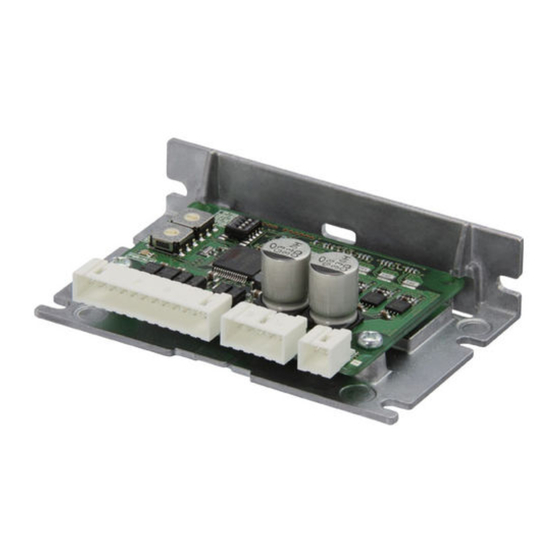
Page 3: Overview Of The Product
Overview of the product Overview of the product The CVD Series multi-axis type EtherCAT compatible is a DC input driver for 2-phase and 5-phase stepping motors. Up to four motors can be connected to a single driver. „ Product lineup Two types of drivers are available, the connector mounting direction is right angle and vertical. -
Page 4: Safety Precautions
Safety precautions Safety precautions The precautions described below are intended to ensure the safe and proper use of the product and to prevent the user and other personnel from exposure to the risk of injury. Use the product only after carefully reading and fully understanding these instructions. - Page 5 Safety precautions General • Do not use the driver beyond the specifications. Doing so may result in injury or damage to equipment. • Do not touch the driver during operation or immediately after stopping. The surface is hot, and this may cause a skin burn(s).
-
Page 6: Precautions For Use
Precautions for use Precautions for use This chapter explains restrictions and requirements that the user should consider when using the product. z When conducting the dielectric strength test, be sure to disconnect the connection between the motor and the driver. Conducting the dielectric strength test with the motor and driver connected may cause damage to the product. -
Page 7: System Configuration
System configuration System configuration Host controller EtherCAT compatible product Driver PC on which the MEXE02 software has been installed*2 Main power supply Control power supply *1 Connect when using direct I/O or sensors. *2 The PC must be supplied by the user. -
Page 8: Preparation
Check the driver model against the model described on the nameplate. Refer to p.9 for how to identify the nameplate. CVD 4A R - K ED Series CVD: CVD Series Number of axes 4A: 4 Axes R: Right-angle Connector shape... - Page 9 Preparation Product type Applicable Series Product to be combined*1 DH Series DHM28PAK2 DHM42PAK Motorized actuators DRLM20 DRLM42 DRLII Series DRLM28 DRLM60 *1 Product models in the table describe part of the whole name of the products. The driver can be combined with products that include the product models listed here.
- Page 10 Preparation Number Name Description Each LED blinks when an alarm is generated in the ALM1 to ALM4 LEDs (Red) corresponding driver section. Node address setting switches Sets the node address of the driver. [SW1 (×10), SW2 (×1)] Factory setting: 0 [SW1 (×10): 0, SW2 (×1): 0] Control power supply connector [CN1] Connects a control power supply.
-
Page 11: Installation
Installation Installation Installation location The driver is designed and manufactured to be incorporated in equipment. Install it in a well-ventilated location that provides easy access for inspection. The location must also satisfy the following conditions: • Inside an enclosure that is installed indoors (provide vent holes) •... - Page 12 Installation Installation method z Horizontal installation Install the driver in the direction shown in the figure. Installing the driver upside down will cause the heat radiation effect to deteriorate. • When the connector shape is “Vertical” • When the connector shape is “Right angle” M3 screw Spring washer Spacer...
- Page 13 Installation „ Dimensions [Unit: mm (in.)] z When the connector shape is “Vertical” Mass: 0.11 kg (0.24 lb.) 160 (6.30) 3.5 (0.14) 153 (6.02) 68 (2.68) 6×ø3.5 THRU (6×ø0.138) z When the connector shape is “Right angle” Mass: 0.11 kg (0.24 lb.) 160 (6.30) 7.9 (0.31) 3.5 (0.14)
-
Page 14: Connection
Connection Connection Connection example Host controller Connect to CN101 Connect to CN5 I/O signal cable*1*2 EtherCAT cable EtherCAT compatible product Driver Connect to CN4 EtherCAT cable PC on which the MEXE02 software has been installed*3 Connect to CN3 USB cable Main power supply Connect to CN2... - Page 15 Connection Connection for motor, encoder, and electromagnetic brake (CN100 to CN400) „ Applicable connector Manufacturer Molex, LLC Connector housing 1053081216 • AWG 20, AWG 22: 1053002200 Contact • AWG 24, AWG 26: 1053001200 • AWG 20, AWG 22: 0638275600 Designated crimp tool •...
- Page 16 Connection „ Connecting 2-phase stepping motors The pin assignments of the connector vary depending on the motor. Refer to the table when connecting. “Colors” in the table indicates the lead wire colors of the Oriental Motor connection cable. Pin numbers are shown in the figures. The model A and model B motors have different pin assignments.
- Page 17 Connection „ Connecting 5-phase stepping motors and motorized actuators The pin assignments of the connector vary depending on the motor. Refer to the table when connecting. “Colors” in the table indicates the lead wire colors of the Oriental Motor connection cable. Pin numbers are shown in the figures.
- Page 18 Connection Connecting the control power supply (CN1) „ Applicable connector Manufacturer Molex, LLC Connector housing 1053071202 Contact 1053002200 Designated crimp tool 0638275600 „ Applicable lead wire Lead size AWG 22, AWG 20 (0.3 to 0.5 mm Outer diameter of wire insulation ø1.60 mm (0.06 in.) Stripping length of wire insulation 2.50 to 3.50 mm (0.10 to 0.14 in.)
- Page 19 Connection • AWG 10: 4.80 to 5.40 mm (0.19 to 0.21 in.) Stripping length of wire insulation • AWG 12: 5.00 to 5.50 mm (0.20 to 0.22 in.) • AWG 16, AWG 14: 4.60 to 5.20 mm (0.18 to 0.20 in.) Keep the wiring distance of the cable as short as possible [2 m (6.6 ft.) or less] to suppress the effect of noise.
- Page 20 Connection Input power supply Power supply Product type Product model*1 voltage current capacity PK513 PK52P 0.6 A or more PKP52MN03 PKP52N03 PK52H PK54 1.4 A or more PKP52MN07 PKP52N07 5-Phase stepping motors 24 VDC±10 % PKP52N12 1.7 A or more PK56*2 1.8 A or more PKP54MN...
- Page 21 Connection „ Pin assignment Signal name Description Transmitted data + N.C. Transmitted data − N.C. Received data + N.C. N.C. − N.C. N.C. − Received data − N.C. − N.C. − Connecting the USB cable (CN3) Using a USB cable with the following specifications, connect a PC on which the MEXE02 software has been installed to the USB connector (CN3).
- Page 22 Connection „ Pin assignment Applicable connector Pin number Signal name Description* Housing insertion direction IN-COM Input common Control input 0 (FW-LS) Control input 1 (RV-LS) Control input 2 (HOMES) Control input 3 (FREE) OUT+ Control output (ALM-B) OUT− IN-COM Input common +24 V Output power supply for sensor * Values in parentheses ( ) are initial values.
- Page 23 Connection z Connection example with a current source output circuit Host controller Driver I/O signal connector IN-COM IN-COM 24 VDC 4.4 kΩ 10 kΩ 4.4 kΩ 10 kΩ 4.4 kΩ 10 kΩ 4.4 kΩ 10 kΩ 4.5 to 26.4 VDC 10 mA or less →...
- Page 24 Connection „ Oriental Motor’s noise suppression products Refer to p.29 for the model. z Surge suppressors These are effective in suppressing the surge that occurs in a contact part of the relay. Connect when using a relay or electromagnetic switch. A CR circuit for surge suppression and a CR circuit module are provided. Compliance with EMC Directive/Regulations Effective measures must be taken against the EMI that the motor and driver may give to adjacent control system equipment, as well as the EMS of the motor and driver itself, to prevent the occurrence of serious malfunctions in the...
- Page 25 Connection z Example of installation and wiring Host controller Shielded cable EtherCAT Grounded panel compatible product Shielded cable DC power supply Shielded cable DC power supply Shielded cable Sensor, switch Shielded cable*3 Shielded cable*2 Shielded cable*1 Shielded cable*2 Sensor, switch Shielded cable*1 Sensor, switch...
-
Page 26: Setting
Setting Setting Setting of node address Set the node address of the driver using two node address setting switches (SW1, SW2). The node address setting switch is hexadecimal. Convert the node address from decimal to hexadecimal to set. When connecting two or more EtherCAT compatible products, set the node addresses so that they are not duplicated. Factory setting: 0 [SW1 (×10): 0, SW2 (×1): 0] Setting range Description... -
Page 27: Inspection And Maintenance
Inspection and maintenance 10 Inspection and maintenance 10-1 Inspection It is recommended that the following items be checked periodically after each operation of the motor. If any abnormality occurs, discontinue use of the product and contact your nearest Oriental Motor sales office. „... -
Page 28: Cables
Cables 11 Cables This chapter describes cables shown in gray in the figure. Driver Connection cable Connection cable (Without termination (Motor side) processing) I/O signal cable Motor Host controller 11-1 Connection cables (Without termination processing) These cables are used to extend the wiring distance between a motor and a driver. „... -
Page 29: Accessories
Accessories 12 Accessories 12-1 Relay contact protection circuit/module z CR circuit for surge suppression This product is effective for the suppression of the surge that occurs in a contact part of the relay. Use it to protect the contacts of the relay or switch. Model: EPCR1201-2 z CR circuit module This product is effective for the suppression of the surge that occurs in a contact part of the relay. -
Page 30: Appendix
Appendix 13 Appendix 13-1 Timing chart „ Power activation 10 s or more Control power supply 0 s or more 1 s or less Main power supply 1.5 s or less 1 s or less SYS-RDY (Output is set, and input is enabled) 2 s or less 1 s or less MPS output... - Page 31 Appendix 13-3 Regulations and standards „ UL Standards, CSA Standards This product is recognized by UL under UL and CSA Standards. „ CE Marking / UKCA Marking This product is affixed with the marks under the following directive/regulations. z EU EMC Directive / UK EMC Regulations Refer to “8-9 Compliance with EMC Directive/Regulations”...
- Page 32 Tel:1800-806-161 4-8-1 Higashiueno, Taito-ku, Tokyo Technical Support Tel:00 800/22 55 66 22 110-8536 Japan Tel:+81-3-6744-0361 Tel:1800-888-881 www.orientalmotor.co.jp/ja Unit 5 Faraday O ce Park, Rankine Road, Basingstoke, Hampshire RG24 8QB UK Tel:1800-120-1995 (For English) Tel:+44-1256347090 1800-121-4149 (For Hindi) Tel:+33-1 47 86 97 50...
Need help?
Do you have a question about the CVD Series and is the answer not in the manual?
Questions and answers