Oriental motor CVD Series Operating Manual
Drivers for 2-phase, 5-phase stepping motors
Hide thumbs
Also See for CVD Series:
- Operating manual (204 pages) ,
- User manual (56 pages) ,
- Operating manual (72 pages)
Advertisement
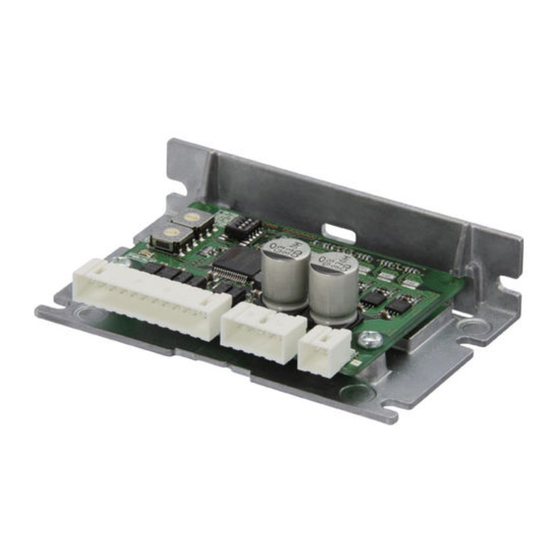
Drivers for 2-Phase, 5-Phase Stepping Motors
CVD Series
Pulse input type
OPERATING MANUAL
1
Introduction .............................. 2
2
Safety precautions ................... 3
3
Precautions for use ................... 5
4
General specifications ............. 6
5
Regulations and standards ..... 7
6
Preparation ................................ 8
7
Installation ............................... 12
Thank you for purchasing an Oriental Motor product.
This Manual describes product handling procedures and safety precautions.
• Please read it thoroughly to ensure safe operation.
• Always keep the manual where it is readily available.
8
Connection .............................. 16
9
Setting ...................................... 28
10 Inspection ................................ 31
11 Alarms ....................................... 32
12 Cables ....................................... 33
13 Accessories............................... 34
HM-60128-11
Advertisement
Table of Contents

Related Manuals for Oriental motor CVD Series


Summary of Contents for Oriental motor CVD Series
-
Page 1: Table Of Contents
Preparation ........ 8 13 Accessories....... 34 Installation ....... 12 Thank you for purchasing an Oriental Motor product. This Manual describes product handling procedures and safety precautions. • Please read it thoroughly to ensure safe operation. • Always keep the manual where it is readily available. -
Page 2: Introduction
The product described in this manual is designed and manufactured to be incorporated in general industrial equipment. Do not use for any other purpose. Oriental Motor Co., Ltd. is not responsible for any compensation for damage caused through failure to observe this warning. -
Page 3: Safety Precautions
Safety precautions Safety precautions The precautions described below are intended to ensure the safe and correct use of the product, and to prevent the customer and others from exposure to the risk of injury. Use the product only after carefully reading and fully understanding these instructions. - Page 4 Safety precautions • Do not use the driver beyond its specifications. Doing so may result in injury or damage to equipment. • Do not insert a finger or an object between the board and the heat sink. Doing so may result in fire or injury. •...
-
Page 5: Precautions For Use
Precautions for use Precautions for use z When conducting the insulation resistance measurement or the dielectric strength test, be sure to separate the connection between the motor and the driver. Conducting the insulation resistance measurement or dielectric strength test with the motor and driver connected may result in damage to the product. -
Page 6: General Specifications
General specifications General specifications Ambient temperature 0 to +50 °C (+32 to +122 °F) (non-freezing) Humidity 85 % or less (non-condensing) Operation environment Altitude Up to 1,000 m (3,300 ft.) above sea level Surrounding atmosphere No corrosive gas, dust, water or oil Ambient temperature −25 to +70 °C (−13 to +158 °F) (non-freezing) Humidity... -
Page 7: Regulations And Standards
Regulations and standards Regulations and standards CE Marking / UKCA Marking This product is affixed with the marks under the following directive/regulations. „ EU EMC Directive / UK EMC Regulations Refer to “8-9 Conformity to the EMC” on p.27 for details about conformity. Republic of Korea, Radio Waves Act This product is affixed with the KC Mark under the Radio Waves Act, the Republic of Korea. -
Page 8: Preparation
Product specifications for possible combinations Use the drivers in combination with the motors (motorized actuators) shown in the table. Check the motor rated current on the Oriental Motor Website or the motor nameplate. „ For 2-phase stepping motor z Type A... - Page 9 Preparation „ For 5-phase stepping motor and motorized actuator z Type A Driver model Driver rated current*1 Product possible to Driver with mounting plate Driver without (A/Phase) combine*2 mounting plate Right angle PKP52 PK513 CVD503BR-K CVD503B-K CVD503-K 0.35 PK52 DRLM20 PKP52...
- Page 10 Preparation Checking the product Verify that the items listed below are included. Report any missing or damaged items to the Oriental Motor sales office from which you purchased the product. • Driver ................1 unit • Instructions and Precautions for Safe Use ..1 copy •...
- Page 11 Preparation „ Driver with mounting plate No.1: 1P/2P switch (pulse input mode) No.2: OFF/SD switch (smooth drive function) No.3: R2/R1 switch (resolution) No.4: STOP switch (standstill current rate) No.5: OFF/FIL switch (command lter) No.6: Not used. CN1 connector (power supply) Cutouts for mounting B (2 places) CN2 connector (motor)
-
Page 12: Installation
Installation Installation Installation location The driver is designed and manufactured to be incorporated in equipment. Install it in a well-ventilated location that provides easy access for inspection. The location must also satisfy the following conditions: • Inside an enclosure that is installed indoors (provide vent holes) •... - Page 13 Installation z Horizontal installation The figure shows the driver with mounting plate. 20 mm (0.79 in.) or more * Provide 40 mm (1.57 in.) clearances for the “driver with mounting plate” of Type A. z Vertical installation The figure shows the driver with mounting plate right angle type. 40 mm (1.57 in.) or more...
- Page 14 Installation Installation method „ Driver without mounting plate z Horizontal installation z Vertical installation Install the driver in a direction shown in the figure. Installing The driver can be installed in any direction. the driver upside down causes the heat radiation effect to deteriorate.
- Page 15 Installation z Vertical installation The driver can be installed in any direction. • When using the cutouts for mounting A • When using the cutouts for mounting B Metal plate Metal plate Spring washers M3 screws Spring washers M3 screws...
-
Page 16: Connection
Connection Connection Connecting the motor Connector pin assignments vary depending on the motor. Refer to the following table. “Color” in the table shows the colors of lead wires of our connection cable. The pin number is shown in the figure. z When 2-phase stepping motor is connected The motors of the Model A and Model B are different in pin assignments. - Page 17 Connection Connection example „ When using the voltage of input signals at 5 VDC Refer to p.18 for when connecting 24 VDC. z When pulse input is of line driver type Controller Driver 2.2 k Twisted pair cable PLS (CW) 2.2 k 2.2 k DIR (CCW)
- Page 18 Connection z When pulse input is of open-collector type Controller Driver Current source Current sink output circuit output circuit 5 VDC 5 VDC 2.2 k Twisted pair cable PLS (CW) 2.2 k 2.2 k DIR (CCW) 2.2 k „ When using the voltage of input signals at 24 VDC z When pulse input is of open-collector type Controller Driver...
- Page 19 Connection • The input voltage specification for the CW input and CCW input is 5 VDC. If the voltage exceeding 5 VDC is applied, connect an external resistor R1 so that the input current becomes 7 to 20 mA. Example) When the 24 VDC is connected: R1 = 1.5 to 2.2 kΩ, 0.5 W or more •...
- Page 20 AWG24 to AWG22 (0.2 to 0.3 mm ) yourself, and connect by using it. Connection cables (without termination processing) of Oriental Motor can also be used. Check on the Oriental Motor Website for the model name. Lead wires of AWG26...
- Page 21 ). To connect the motor lead wires thinner than AWG20, provide lead wires of AWG20 to AWG18 by yourself, and relay to connect. Connection cables (without termination processing) of Oriental Motor can also be used. Check on the Oriental Motor Website for the model name. Motor lead wires...
- Page 22 Connection Connecting the power supply Use a power supply that can supply the following current capacity. When the power supply is turned on, the PWR/ALM LED will be lit in green. „ For 2-phase stepping motor Driver model Input power supply voltage Power supply current capacity CVD205 0.5 A or more...
- Page 23 Connection Explanation of I/O signals „ Input signals The signal input state represents “ON: Carrying current” or “OFF: Not carrying current” state of the internal photocoupler. The interval for switching the motor direction represents the response time of the circuit. Set this interval to an appropriate time after which the motor will respond.
- Page 24 Connection „ Output signals The driver outputs signals are photocoupler/open-collector output. The signal output state represents “ON: Carrying current” or “OFF: Not carrying current” state of the internal photocoupler. z ALM (alarm) output The ALM output is normally closed. If an alarm is generated, the ALM output is turned OFF to put the motor into a non-excitation state.
- Page 25 Connection Timing chart Motor operation Power supply input 0.2 s or less 10 s or less ALM output 0.1 s or more CW input 2-pulse 5 µs or more 0.2 s or more input mode CCW input 5 µs or more 5 µs or more PLS input 1-pulse...
- Page 26 Connection Noise elimination measures There are two types of electrical noises: One is a noise to invade into the driver from the outside and cause the driver malfunction, and the other is a noise to emit from the driver and cause peripheral equipment malfunction. For the noise that is invaded from the outside, take measures to prevent the driver malfunction.
- Page 27 The use of the following installation and wiring methods will enable the motor and driver to be compliant with the EMC. Oriental Motor conducts EMC testing on its motors and drivers in accordance with the “Example of motor and driver installation and wiring. ”...
-
Page 28: Setting
Setting Setting No.1: 1P/2P switch (pulse input mode) STEP switch No.2: OFF/SD switch (smooth drive function) (step angle) No.3: R2/R1 switch (resolution) No.4: STOP switch (standstill current rate) RUN switch (operating current rate) No.5: OFF/FIL switch (command lter) No.6: Not used. The STEP switch, 1P/2P switch, and R2/R1 switch are enabled after the power supply is turned on again. - Page 29 Setting • Step angles are theoretical values. • Do not change the CS input or switches while operating. Doing so may cause loss of synchronism of the motor, resulting in the motor standstill. • For the high-resolution type, in comparison with the standard type the resolution is twice and the step angle is one-half.
- Page 30 Setting Standstill current When the motor stops, the current cutback function will be actuated to lower the motor current to the standstill current. The driver standstill current rate can be switched between 25 % and 50 % using the STOP switch. When setting the switch to the OFF side, the standstill current rate will be set to 25 %.
-
Page 31: Inspection
10 Inspection It is recommended that periodic inspections are conducted for the items listed below after each operation of the motor. If an abnormal condition is noted, discontinue any use and contact your nearest Oriental Motor sales office. Inspection item •... -
Page 32: Alarms
Excessive current was flowed through Overcurrent that the motor, cable and driver are not the driver output circuit for motor. damaged. EEPROM The stored data in the driver was Contact your nearest Oriental Motor error damaged. sales office. Light CPU error CPU malfunctioned. -
Page 33: Cables
Cables 12 Cables 12-1 Connection cable sets For the connection cable set, a set of three cables for the power supply, motor, and input/output signals is provided. Model Applicable driver Length [m (ft.)] Conductor LCS01CVK2 Type A AWG22 (0.3 mm AWG20 (0.5 mm LCS02CVK2 Type B... -
Page 34: Accessories
Accessories 13 Accessories „ Pulse signal converter for noise immunity This product converts a pulse signal, which is output from the open collector output, to a pulse signal for good noise immunity by outputting the pulse signal again from the differential output. Model: VCS06 „... - Page 36 • Unauthorized reproduction or copying of all or part of this manual is prohibited. • Oriental Motor shall not be liable whatsoever for any problems relating to industrial property rights arising from use of any information, circuit, equipment or device provided or referenced in this manual.
Need help?
Do you have a question about the CVD Series and is the answer not in the manual?
Questions and answers