Oriental motor CVD Series Operating Manual
Drivers for 5-phase stepping motors
Hide thumbs
Also See for CVD Series:
- Operating manual (204 pages) ,
- User manual (56 pages) ,
- Operating manual (9 pages)
Table of Contents
Advertisement
Quick Links
Drivers for 5-Phase Stepping Motors
CVD Series
Fully Closed-Loop Control Type
OPERATING MANUAL
Thank you for purchasing an Oriental Motor product.
This Operating Manual describes product handling procedures and safety precautions.
• Please read it thoroughly to ensure safe operation.
• Always keep the manual where it is readily available.
HM-60522
Advertisement
Table of Contents

Subscribe to Our Youtube Channel
Related Manuals for Oriental motor CVD Series


Summary of Contents for Oriental motor CVD Series
- Page 1 CVD Series Fully Closed-Loop Control Type OPERATING MANUAL Thank you for purchasing an Oriental Motor product. This Operating Manual describes product handling procedures and safety precautions. • Please read it thoroughly to ensure safe operation. • Always keep the manual where it is readily available.
-
Page 2: Table Of Contents
Introduction ..........3 Setting ............. 34 1-1 Before using the product ........3 8-1 Setting of motor ..........34 1-2 About operating manuals ......3 8-2 Setting of resolution ........35 1-3 How to use operating manuals ....3 8-3 Setting of pulse input mode ....... 36 1-4 Overview of the product .........4 8-4 Setting related to the fully closed-loop correction ............ -
Page 3: Introduction
The product described in this manual is designed and manufactured to be incorporated into general industrial equipment. Do not use it for any other purpose. Oriental Motor Co., Ltd. is not responsible for any compensation for damage caused through failure to observe this warning. -
Page 4: Overview Of The Product
Introduction Overview of the product The CVD Series fully closed-loop control type driver is a DC input driver for 5-phase stepping motors. „ Equipped with the fully closed-loop correction function The fully closed-loop correction function is a function that corrects the positional displacement of the motor with high accuracy using the information from the externally installed encoder. -
Page 5: Safety Precautions
Safety precautions Safety precautions The precautions described below are intended to ensure the safe and proper use of the product and to prevent the user and other personnel from exposure to the risk of injury. Use the product only after carefully reading and fully understanding these instructions. - Page 6 Safety precautions General • Do not use the driver beyond the specifications. Doing so may result in injury or damage to equipment. • Do not insert a finger or an object between the board and the heat sink. Doing so may result in fire or injury. •...
-
Page 7: Precautions For Use
Precautions for use Precautions for use This chapter explains restrictions and requirements that the user should consider when using the product. z When conducting the insulation resistance measurement or the dielectric strength test, be sure to separate the connection between the motor and the driver. Conducting the insulation resistance measurement or the dielectric strength test with the motor and driver connected may result in damage to the product. -
Page 8: Preparation
Preparation Preparation Checking the product Verify that the items listed below are included. Report any missing or damaged items to the Oriental Motor sales office from which you purchased the product. • Driver ................1 unit • Instructions and Precautions for Safe Use ..1 copy When taking out the driver from the electrostatic discharge (ESD) protection bag, make sure your hands are not charged with static electricity. -
Page 9: Information About Nameplate
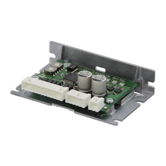
Preparation Information about nameplate The figure shows an example. Driver model Serial number Manufacturing date The position describing the information may vary depending on the product. Names and functions of parts The figure shows the driver whose connector shape is right-angle. Cutout for mounting B (2 places) Termination resistor setting switch (SW2) -
Page 10: Indication Of Leds
Preparation Type Name Description RS-485 connector (CN4) Connect a host controller. Encoder input Connects the encoder. connector (CN5) Connectors I/O signal connector Connects the I/O signal cable. (CN6) Encoder output Signals input to the CN5 connector are output. connector (CN7) Indication of LEDs The status of the driver and RS-485 communication can be checked using the indication of LEDs. -
Page 11: Installation
Installation Installation Installation location The driver is designed and manufactured to be incorporated into equipment. Install it in a well-ventilated location that provides easy access for inspection. The location must also satisfy the following conditions: • Inside an enclosure that is installed indoors (provide vent holes) •... - Page 12 Installation z Vertical installation [Unit: mm (in.)] 40 (1.57) or more...
-
Page 13: Installation Method
Installation Installation method Install the driver using either the cutouts for mounting A or B. The tightening torque of the mounting screws should be 0.5 N·m (71 oz-in). The figure shows the driver whose connector shape is right-angle. If both cutouts for mounting A and B are used for installation, the heat sink is distorted, causing stress on the board. - Page 14 Installation „ Dimensions [Unit: mm (in.)] z When the connector shape is “Right angle” Mass: 67 g (0.15 lb.) 24.5 max. (0.96 max.) 85 (3.35) 3.5 (0.14) 78 (3.07) (0.79) 2 (0.08) 3.5 (0.14) 78 (3.07) z When the connector shape is “Vertical” Mass: 67 g (0.15 lb.) 24.5 max.
-
Page 15: Connection
Connect to CN5 +24 V Encoder input cable *1 It is provided in Oriental Motor products. *2 The PC must be supplied by the user. • When connecting, pay attention to the polarity of the main power supply. Connecting the main power supply with the wrong polarity may cause damage to the driver. -
Page 16: Connecting The Main Power Supply (Cn1)
Connection Connecting the main power supply (CN1) „ Power supply current capacity • The current capacity for the main power supply varies depending on the product combined. • Models in the table describe part of the entire name of models. The box ( ... -
Page 17: Connecting The Motor, Motorized Actuator (Cn2)
The pin assignments of the connector vary depending on the motor. Refer to the table when connecting. “Colors” in the table indicates the lead wire colors of the Oriental Motor connection cable or motor. Pin numbers are shown in the figures. -
Page 18: Connecting The Rs-485 Communication Compatible Product (Cn4)
Connection Connecting the RS-485 communication compatible product (CN4) Connect the RS-485 cable to the RS-485 connector (CN4) on the driver. „ Pin assignment Pin number Signal name Description RS-485 communication signal positive side TR− RS-485 communication signal negative side 1 2 3 „... -
Page 19: Connecting The External Encoder (Cn5)
Connection Connecting the external encoder (CN5) Connect the external encoder to the encoder input connector (CN5). „ Pin assignment Pin number Signal name Description ENC-A+ Encoder input phase A (Line receiver) ENC-A− ENC-B+ 3 5 7 9 Encoder input phase B (Line receiver) ENC-B−... - Page 20 Connection „ Specifications of encoder input section Type Item Description Input mode Incremental Maximum frequency 4.0 MHz*1 Edge interval 62.5 nsec or more Phase A Count range −2,147,483,648 to +2,147,483,647 counts Phase B Count system 90-degree phase difference input Multiplication number ×1, ×2, ×4*2 Interface Differential line receiver (26C32 equivalent)
-
Page 21: Connecting The I/O Signals (Cn6)
Connection Connecting the I/O signals (CN6) „ Pin assignment Pin number Signal name*1 Description*1*2 CW pulse input positive side CW+ [PLS+] [Pulse input positive side] CW pulse input negative side CW− [PLS−] [Pulse input negative side] CCW pulse input positive side CCW+ [DIR+] [Rotation direction input positive side] CCW pulse input negative side... - Page 22 Connection „ When the voltage of input signals is 5 VDC z When the pulse input circuit of the driver is line driver type Host controller Driver 2.2 k 2.2 k Twisted-pair wires CW+ (PLS+) CW− (PLS−) 2.2 k 2.2 k CCW+ (DIR+) CCW−...
- Page 23 Connection z When the pulse input circuit of the driver is open collector type Host controller Driver Current source Current sink output circuit output circuit 5 VDC 5 VDC 2.2 k 2.2 k Twisted-pair wires CW+ (PLS+) CW− (PLS−) 2.2 k 2.2 k CCW+ (DIR+) CCW−...
- Page 24 Connection „ When the voltage of input signals is 24 VDC z When the pulse input circuit of the driver is open collector type Host controller Driver Current source Current sink output circuit output circuit 24 VDC 1.5 to 2.2 k 24 VDC 0.5 W or more 2.2 k...
-
Page 25: Connecting The Counter (Cn7)
Connection Connecting the counter (CN7) This is an output of the encoder signal connected to the encoder input connector (CN5). When a counter dedicated to the encoder or a high-speed counter module of the PLC is connected to the encoder output connector (CN7), the feedback position can be monitored. -
Page 26: Noise Elimination Measures
• Change the transmission method of pulse signals to the line driver type which is less likely to be affected by electrical noise. If the pulse signal of the host controller is open collector type, use Oriental Motor’s pulse signal converter for noise immunity. -
Page 27: Compliance With The Emc Directive/Regulations
Use of the following installation and wiring methods will enable the motor and driver to comply with the EMC Directive/Regulations. Oriental Motor conducts EMC testing on its motors and drivers in accordance with “Example of installation and wiring” on p.28. - Page 28 Connection z Example of installation and wiring Connection cable Table Motor Linear encoder Shielded cable Host controller*2 Shielded Cable clamp DC power cable Shielded supply cable Encoder counter Cable Cable Shielded clamp clamp cable Driver Host controller Cable Cable Shielded clamp clamp cable...
-
Page 29: Explanation Of I/O Signals
Explanation of I/O signals Explanation of I/O signals This chapter explains the signals assigned to the I/O signal connector at the time of shipment. Input signals All input signals of the driver are photocoupler inputs. The signal state represents a state of “ON: Carrying current” or “OFF: Not carrying current”... -
Page 30: Output Signals
Explanation of I/O signals „ FCLOOP-DIS input If the FCLOOP-DIS input is turned ON when the “Fully closed-loop correction enable” parameter is set to “1: Enable, ” the correction by the fully closed-loop control is disabled. Also, the FCLOOP-RDY input is turned OFF. To disable the FCLOOP-DIS input, set the “Fully closed-loop mode”... - Page 31 Explanation of I/O signals • If a value set in the “In-position range” parameter is too low, the ENC-IN-POS output will be unstable depending on the environmental conditions of the equipment and will be turned ON and OFF repeatedly. • If the “In-position range” parameter is set to “0, ” the ENC-IN-POS output is turned ON when the position deviation (cnt) is 1 cnt or less.
-
Page 32: Timing Chart
Explanation of I/O signals Timing chart z Main power supply ON 10 s or more Main power supply 1 s or less 1 s or less SYS-RDY output Fixed (Output is set and Not xed input is enabled) 1 s or less 1 s or less RS-485 communication Ready... - Page 33 Explanation of I/O signals z Excitation Excitation command 200 ms or less 2 ms or less CRNT output 200 ms or less 2 ms or less PLS-RDY output 200 ms or less 2 ms or less READY output 200 ms or less 2 ms or less DCMD-RDY output 200 ms or less...
-
Page 34: Setting
Setting Setting Setting of motor Set the “Applicable motor setting” parameter according to the product to be combined. If the parameter is set, the output current of the driver is automatically set. Be sure to set in accordance with the product being combined. If the output current of the driver is accidentally set to a value higher than the rated current of the motor being combined, fire or a skin burn(s) may result. -
Page 35: Setting Of Resolution
Setting z Related parameter MEXE02 Initial Name Description Setting range code value 0: No setting Sets the output current of the driver 18: 5-phase, 0.35 A/phase according to the product to be 19: 5-phase, 0.75 A/phase Applicable motor combined. 20: 5-phase, 1.2 A/phase setting Check “Parameter setting values for the 21: 5-phase, 1.4 A/phase... -
Page 36: Setting Of Pulse Input Mode
Setting Setting of pulse input mode Set the pulse input mode of the driver according to the pulse output mode of the host controller used. Related parameters MEXE02 code Name Description Setting range Initial value −1: Disable PULSE-I/F mode selection Sets the pulse input mode. - Page 37 Setting „ Encoder resolution Set the related parameters according to the encoder to be used. Related parameters Initial MEXE02 Name Description Setting range code value Selects the type of the encoder 0: Linear Encoder type to be connected. 1: Rotary Sets the resolution of the linear Linear encoder resolution 1 to 50,000 nm...
- Page 38 Setting z Relationship between encoder input waveform and feedback position The feedback position when the “Multiplication number” parameter and “Encoder count action” parameter are set is as follows. The figure shows an example when the “Encoder count action” parameter is set to “1: Counting up. ” When the “Encoder count action”...
- Page 39 Setting Multiplication Count action Waveform number ENC-A+ ENC-A− ×1 multiplication Counting down ENC-B+ ENC-B− Feedback position „ Fully closed-loop correction function z Adjustment of correction range The correction range when the fully closed-loop correction is performed can be adjusted. The deviation between the command position and the feedback position is monitored and the motor position is corrected until the deviation falls within the range set in the “In-position range”...
- Page 40 Setting z Adjustment of the correction upper limit The upper limit of the correction amount when the fully closed-loop correction is performed can be set. Adjust according to the position deviation between the motor and the encoder caused by backlash or torsion of the mechanism.
- Page 41 Setting Related parameters MEXE02 Initial Name Description Setting range code value Fully closed-loop Enables the correction by the fully 0: Disable correction enable closed-loop control. 1: Enable Selects whether to enable or disable 0: Follow FCLOOP-DIS the fully closed-loop correction input Fully closed-loop mode according to the FCLOOP-DIS input...
- Page 42 Setting z Timing chart How to start the correction function 1. Check that the READY output is being ON. 2. Turn the P-PRESET input ON. The ABSPEN output is turned ON and the FCLOOP-RDY output is turned ON. Main power supply 1 s or less SYS-RDY output Fixed...
- Page 43 Setting Relationship between signals during correction operation 1. Check that the FCLOOP-RDY output is in an ON state. 2. Execute operation. During operation, the FCLOOP-RDY output and the READY output are turned OFF, and the MOVE output is turned ON. During this time, the position correction is not performed. 3.
- Page 44 Setting „ Automatic position preset function After the main power supply is turned on and the motor is excited for the first time, position preset is automatically executed to set the coordinates. Related parameters Initial MEXE02 Name Description Setting range code value Sets whether or not to automatically...
-
Page 45: Setting Of Operating Current And Stop Current
Setting Setting of operating current and stop current The operating current and the stop current are calculated based on the base current (%). The base current is a current used to set the operating current and the stop current and is set as a percentage (%) of the maximum output current of the driver. -
Page 46: Setting Of Command Filters
Setting Setting of command filters Using the command filter to adjust the motor response can suppress motor vibration. There are two types of command filters, LPF (speed filter) and moving average filter. Related parameters MEXE02 Initial Parameter name Description Setting range code value Sets the filter function to adjust... -
Page 47: Inspection And Maintenance
Inspection It is recommended that the following items be checked periodically after each operation of the motor. If any abnormality occurs, discontinue use of the product and contact your nearest Oriental Motor sales office. „ Inspection items • Check to see if any of the mounting screws secured the driver are loose. -
Page 48: 10 Alarms
The alarm content cannot be checked via RS-485 communication. Check with the alarm monitor of the MEXE02 software. This is the code to be checked by Oriental Motor. However, when the operation data error (alarm code 70h) occurs, the cause of the alarm Sub code can be checked by a customer if the sub code is used. - Page 49 Alarms Name Description Indicates the amount of time elapsed from when the main power supply was first turned Power supply time on to when an alarm was generated. The R-I/O output is monitored internally even if RS-485 communication is not used. If an output signal to be monitored is assigned to the R-OUT output, the number of monitors when an alarm is generated can be increased.
-
Page 50: Alarm List
Contact your nearest Oriental Motor sales office. The board temperature of Main circuit Reconsider the ventilation Non- the driver exceeded 85 °C... - Page 51 Alarms Number Reset using Alarm Motor of LED Alarm type Cause Remedial action the ALM-RST code excitation* blinks input • Check the connection of the external encoder. • Reconsider “In-position range” parameter. • Reconsider the setting of the “Correction speed During the fully closed-loop gain”...
- Page 52 Alarms Number Reset using Alarm Motor of LED Alarm type Cause Remedial action the ALM-RST code excitation* blinks input The HOMES input was not detected at a position between the FW-LS input Install the HOME sensor at a No HOMES and the RV-LS input while position between the Possible...
- Page 53 Alarms Number Reset using Alarm Motor of LED Alarm type Cause Remedial action the ALM-RST code excitation* blinks input The time set in the “Communication timeout” RS-485 Check the connection parameter has elapsed, and communication between the driver and the Possible Excitation yet the communication...
-
Page 54: Timing Chart
Alarms 10-4 Timing chart „ When the motor remains in an excitation state even if an alarm is generated 1. If an error occurs, the ALM-B output, the MOVE output, and the PLS-RDY output are turned OFF. At the same time, the motor stops immediately. 2. - Page 55 Alarms „ When the motor goes into a non-excitation state if an alarm is generated 1. If an error occurs, the ALM-B output, the MOVE output, and the PLS-RDY output are turned OFF. At the same time, the motor stops immediately. 2.
-
Page 56: 11 Information
Information 11 Information The driver is equipped with a function to generate information output before an alarm is generated. This function can be used for periodic maintenance of equipment by setting a appropriate value in the parameter of each information. For example, setting the “Tripmeter information”... -
Page 57: Clearing Information
Information Initial MEXE02 Name Description Setting range code value INFO action (Start operation error information (INFO-START)) INFO action (PRESET request information (INFO-PR-REQ)) INFO action (Motor setting error information (INFO-MSET-E)) INFO action (Electronic gear setting error information (INFO-EGR-E)) INFO action (RS-485 communication error information (INFO-NET-E)) INFO action (Forward operation... -
Page 58: Information History
Information 11-2 Information history Up to 16 generated information items are stored in RAM in order from most recent to oldest. Information items stored as the information history are the information code, generation time, and contents of information. The stored information history can be read or cleared if one of the following operations is performed. •... -
Page 59: Information List
Information z Information codes Information codes are displayed in eight hexadecimal digits. They can also be read in 32 bits. If multiple information items are generated, the logical sum (OR) of the information codes is displayed. Example) When information items of the driver temperature and the overvoltage are generated Information code of Driver temperature: 0000 0004h Information code of Overvoltage: 0000 0010h... - Page 60 Information Information bit Information item Cause Condition to clear output signal • The operation start signal in the direction that was stopped by the FW-BLK input or RV-BLK input has been turned ON. • The operation start signal in the direction that was stopped by the FW-LS input or RV-LS input has been turned ON.
- Page 61 Information Information bit Information item Cause Condition to clear output signal • “Teaching, remote operation” was executed using the MEXE02 • Teaching, remote operation was software. canceled. • Configuration was executed. • Configuration was completed. Start operation INFO-DSLMTD restricted mode •...
-
Page 62: 12 Troubleshooting And Remedial Actions
In motor operation, the motor or the driver may not operate properly due to an improper setting or incorrect connection. When the motor cannot be operated properly, refer to the contents provided in this chapter and take an appropriate remedial action. If the problem persists, contact your nearest Oriental Motor sales office. Phenomenon Possible cause Remedial action... - Page 63 Troubleshooting and remedial actions Phenomenon Possible cause Remedial action The centers of the output shaft and the Check the connection condition of the output shaft load shaft are not aligned. and the load shaft. Check to see if large load fluctuations have occurred The load fluctuation is large.
- Page 64 Troubleshooting and remedial actions Phenomenon Possible cause Remedial action • Check the connection of the external encoder. • Increase the acceleration/deceleration time or slow down the acceleration/deceleration rate, and The fully closed-loop An alarm of Encoder excessive position perform operation with the time that can be started correction is not performed.
-
Page 65: 13 Cables
Cables 13 Cables This chapter describes cables shown in gray in the figure. Host controller RS-485 cable Driver Connection cable Connection cable Connection cable (Motor side) (Without termination processing) (Driver side) Main power supply Motor DC power supply cable In addition to the cables described here, there are several types of connection cables available, such as those that can be connected directly between the motor and the driver. -
Page 66: Connection Cables (Without Termination Processing)
Cables 13-4 Connection cables (Without termination processing) These cables are used to extend the wiring distance between a motor and a driver. „ Connection cables Model Length [m (ft.)] Electrical wire size Outer diameter CC05PK5 5 (16.4) AWG22 (0.3 m ø7.2 mm CC10PK5 10 (32.8) -
Page 67: 14 Accessories
Accessories 14 Accessories 14-1 Relay contact protection circuit/module „ Pulse signal converter for noise immunity This product converts a pulse signal, which is output from the open collector output, to a pulse signal for good noise immunity by outputting the pulse signal again from the differential output. Model: VCS06 „... -
Page 68: 15 Specifications
Specifications 15 Specifications 15-1 Product specifications Input voltage 24 VDC±10 % Input current 0.6 to 3.0 A* • 3 to 5.25 VDC • Maximum input pulse frequency Pulse input Line driver output: 1 MHz (duty cycle 50 %) Open-collector output: 250 kHz (duty cycle 50 %) Control input 4.5 to 5.25 VDC 30 VDC or Less (output saturation voltage: maximum 0.5 V) -
Page 69: 16 Regulations And Standards
Regulations and standards 16 Regulations and standards 16-1 UL Standards, CSA Standards This product is recognized by UL under UL and CSA Standards. 16-2 CE Marking / UKCA Marking This product is affixed with the marks under the following directives/regulations. „... - Page 72 If a new copy is required to replace an original manual that has been damaged or lost, please contact your nearest Oriental Motor sales office. • Oriental Motor shall not be liable whatsoever for any problems relating to industrial property rights arising from use of any information, circuit, equipment or device provided or referenced in this manual.
Need help?
Do you have a question about the CVD Series and is the answer not in the manual?
Questions and answers