Oriental motor CVD Series User Manual
Drivers for 2-phase, 5-phase stepping motors, rs-485 communication type
Hide thumbs
Also See for CVD Series:
- Operating manual (204 pages) ,
- Operating manual (16 pages) ,
- Operating manual (72 pages)
Table of Contents
Advertisement
Drivers for 2-Phase, 5-Phase Stepping Motors
CVD Series
RS-485 communication type
USER MANUAL
Thank you for purchasing an Oriental Motor product.
This Manual describes product handling procedures and safety precautions.
• Please read it thoroughly to ensure safe operation.
• Always keep the manual where it is readily available.
HM-60392
Advertisement
Table of Contents

Related Manuals for Oriental motor CVD Series


Summary of Contents for Oriental motor CVD Series
- Page 1 CVD Series RS-485 communication type USER MANUAL Thank you for purchasing an Oriental Motor product. This Manual describes product handling procedures and safety precautions. • Please read it thoroughly to ensure safe operation. • Always keep the manual where it is readily available.
-
Page 2: Table Of Contents
How to use * * This manual describes contents from checking the product to settings related to RS-485 communication. Refer to the CVD Series RS-485 communication type STEP 1 Checking the product ....8 OPERATING MANUAL Function Edition for control methods via Modbus RTU (RS-485 communication) as Package contents ............ -
Page 3: Before Use
The product described in this manual is designed and manufactured to be incorporated in general industrial equipment. Do not use for any other purpose. Oriental Motor Co., Ltd. is not responsible for any damage caused through failure to observe this warning. -
Page 4: Overview Of The Product
Before use Overview of the product The CVD Series RS-485 communication type drivers are DC power input products for 2-phase and 5-phase stepping motors. „ Lineup Two types of drivers, which are for 2-phase stepping motors and 5-phase stepping motors, are provided. -
Page 5: Safety Precautions
Safety precautions Safety precautions The precautions described below are intended to prevent danger or injury to the user and other personnel through safe, correct use of the product. Use the product only after carefully reading and fully understanding these instructions. Handling the product without observing the instructions that accompany a “WARNING”... - Page 6 Safety precautions General • Do not use the driver beyond its specifications. Doing so may result in electric shock, injury, or damage to equipment. • Do not insert a finger or an object between the board and the heat sink. Doing so may result in fire, electric shock, or injury.
-
Page 7: Precautions For Use
Precautions for use Precautions for use This chapter covers restrictions and requirements the user should consider when using the product. z When conducting the insulation resistance measurement or the dielectric strength test, be sure to separate the connection between the motor and the driver. Conducting the insulation resistance measurement or dielectric strength test with the motor and driver connected may result in damage to the product. -
Page 8: Step 1
STEP 1 Checking the product Package contents Verify that the items listed below are included. Report any missing or damaged items to the Oriental Motor sales office from which you purchased the product. • Driver ............1 unit • OPERATING MANUAL Driver ..... 1 copy When taking out the driver from the electrostatic discharge (ESD) protection bag, make sure your hands are not charged with static electricity. -
Page 9: Products Possible To Combine
Checking the product Products possible to combine Products with which the driver can be combined are listed below. Check the model name of the product with the nameplate. Driver model Product type Applicable Series Motor model *1 PKP213D05„ PKP24D23„2 PKP214D06„ PKP24MD15„2 PKP22D15„... -
Page 10: Names And Functions Of Parts
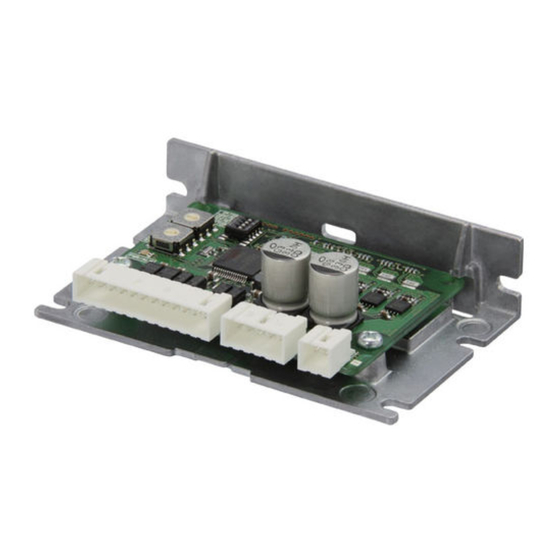
Checking the product Names and functions of parts The figure shows the driver which connector shape is of right angle. Cutouts for mounting B (2 places) Power supply connector (CN1) Motor connector (CN2) Motor setting switch USB communication connector (CN3) (SW1) RS-485 communication connector (CN4, CN5) I/O signal connector (CN6) -
Page 11: Step 2 Installation
Installation STEP 2 Installation Installation location The driver is designed and manufactured to be incorporated in equipment. Install it in a well-ventilated location that provides easy access for inspection. The location must also satisfy the following conditions: • Inside an enclosure that is installed indoors (provide vent holes) •... - Page 12 Installation z Vertical installation [Unit: mm (in.)] 40 (1.57) or more...
-
Page 13: Installation Method
Installation Installation method Install the driver using either the “cutouts for mounting A” or “cutouts for mounting B. ” Torque the mounting screw to 0.5 N·m (71 oz-in). The figure shows the driver which connector shape is of right angle. If both cutouts A and B are used for installation, the heat sink is distorted, causing the board to apply stress. - Page 14 Installation „ Dimension [Unit: mm (in.)] The figure shows the driver which connector shape is of right angle. Mass: 0.065 kg (2.3 oz.) 24.5 max. (0.96 max.) 85 (3.35) (0.79) 3.5 (0.14) 78 (3.07) 2 (0.08) 3.5 (0.14) 78 (3.07)
-
Page 15: Step 3
Connection STEP 3 Connection „ Connection example Host controller Connect to CN6 I/O signal cable *1 *2 Connect to CN4 or CN5 RS-485 communication cable (For connecting host controller) *1 RS-485 communication compatible product RS-485 communication cable (For connecting between drivers) *1 PC in which the MEXE02 has been installed *3 Connect to CN4 or CN5... -
Page 16: Connecting The Motor (Cn2): 2-Phase Stepping Motor
Connection Connecting the motor (CN2): 2-phase stepping motor Connector pin assignments vary depending on the motor. Refer to the table when connecting. The pin number is shown in the figure. “Color” in the table shows the colors of lead wires of our connection cable. The motors of the model A and model B are different in pin assignments. -
Page 17: Connecting The Motor (Cn2): 5-Phase Stepping Motor
Connection Connecting the motor (CN2): 5-phase stepping motor Connector pin assignments vary depending on the motor. Refer to the table when connecting. The pin number is shown in the figure. “Color” in the table shows the colors of lead wires of our connection cable. The motors of the model A and model B are different in pin assignments. -
Page 18: Connecting The Main Power Supply (Cn1)
Connection Connecting the main power supply (CN1) „ Power supply current capacity The current capacity of the main power supply varies depending on the product to be combined. z 2-phase stepping motor Motor model * Input power supply voltage Power supply current capacity PKP213D05„... -
Page 19: Connecting The Rs-485 Communication Compatible Product (Cn4, Cn5)
Connection „ Applicable connector Manufacturer Molex Incorporated Connector housing 43645-0200 Contact 43030-0001 Designated crimping tool 638190000 • AWG22 (0.3 mm • Outer sheath diameter: Applicable lead wire ø1.85mm (ø0.073 in.) • Stripping length of wire insulation: 2.54 to 2.92 mm (0.1 to 0.115 in.) Keep the wiring distance as short as possible [less than 2 m (6.6 ft.)] to suppress the effect of noise. - Page 20 Connection „ Internal output circuit SG is insulated from the internal GND. Driver 1 RS-485 TR− No.2 No.1 TR− Driver 2 TR− No.2 No.1 TR− Driver 31 TR− No.2 *2 No.1 *2 *1 Termination resistor (120 Ω) *2 Turn the termination resistor to ON.
-
Page 21: Connecting The Usb Cable (Cn3)
Connection Connecting the USB cable (CN3) Using a USB cable of the following specification, connect a PC in which the MEXE02 has been installed to the USB communication connector (CN3). Specification USB2.0 (full speed) Length: 3 m (9.8 ft.) or less Cable Shape: A to mini B •... - Page 22 Connection „ Connection example with a current sink output circuit The value in parentheses ( ) is the initial value. Host controller Driver 6.8 k IN0 (FW-POS) 2.2 k 6.8 k IN1 (RV-POS) 2.2 k 6.8 k IN2 (STOP) 2.2 k 6.8 k IN3 (ALM-RST) 2.2 k...
- Page 23 Connection „ Connection example with a current source output circuit The value in parentheses ( ) is the initial value. Host controller Driver 24 VDC 6.8 k IN0 (FW-POS) 2.2 k 6.8 k IN1 (RV-POS) 2.2 k 6.8 k IN2 (STOP) 2.2 k 6.8 k IN3 (ALM-RST)
-
Page 24: Step 4 Setting The Applicable Motor
Setting the applicable motor STEP 4 Setting the applicable motor Set the motor setting switch (SW1) according to the motor used. If the switch is set, the output current of the driver is automatically set. • Be sure to set the switch according to the motor. If the output current of the driver is set to a value higher than the rated current of the motor by mistake, fire or a skin burn(s) may result. - Page 25 Setting the applicable motor „ 5-phase stepping motor Factory setting 0 (No setting) Output current of driver to be set Setting of switch Motor model * (A/phase) PK513 0.35 PK52P PK52H 0.75 PK54 PKP52 PK56 PKP54N18„2 PKP54MN PKP56FN24„2 PKP56FMN * The motor model column in the table describes part of the entire name of models. The box ( ...
-
Page 26: Step 5 Settings Related To Rs-485 Communication
Settings related to RS-485 communication STEP 5 Settings related to RS-485 communication Setting of termination resistor Set the termination resistor (120 Ω) of RS-485 communication to the driver located the farthest away (positioned at the end) from the host controller. Set both No.1 and No.2 of the termination resistor setting switch (SW2) to ON. -
Page 27: Setting Of Communication Parameters
Settings related to RS-485 communication Setting of communication parameters Set parameters required for RS-485 communication before performing communication. „ Parameters updated when turning on the main power supply These are parameters related to sending/receiving via RS-485 communication. Parameters are recommended to set using the MEXE02. - Page 28 Settings related to RS-485 communication Setting example of the “Byte & word order (Modbus)” parameter When 32-bit data “12345678h” is stored at the register addresses 1000h and 1001h, arrangement is changed as follows depending on the setting of parameters. 1000h (even address) 1001h (odd address) Setting of parameters Upper...
-
Page 29: Inspection And Maintenance
Inspection It is recommended that periodic inspections are conducted for the items listed below after each operation of the motor. If an abnormal condition is noted, discontinue any use and contact your nearest Oriental Motor sales office. „ Inspection item •... -
Page 30: Alarms
Alarms Alarms This driver has the alarm function to protect from temperature rise, poor connection, error in operation, and others. If an alarm is generated, the ALM-A output is turned ON and the ALM-B output is turned OFF to stop the motor. At the same time, the PWR/ALM LED blinks in red. - Page 31 If the alarm is still not excitation were short-circuited. reset, the motor, the cable, or the driver may be damaged. Contact your nearest Oriental Motor sales office. The board temperature of Main circuit Reconsider the ventilation Non- the driver exceeded 85 °C...
- Page 32 Alarms Number of Reset using Alarm Motor times LED Alarm type Cause Remedial action the ALM-RST code excitation * blinks input The LS input opposite to the operating direction was detected while Reverse ±LS Check the wiring of the return-to-home operation Possible Excitation connection...
- Page 33 Alarms Number of Reset using Alarm Motor times LED Alarm type Cause Remedial action the ALM-RST code excitation * blinks input When offset movement as Return-to-home part of return-to-home operation offset operation is performed, Check the offset value. Possible Excitation error the FW-LS input or the RV-LS input was detected.
- Page 34 Alarms Monitor of alarm history The alarm history can be checked via RS-485 communication or using the MEXE02. The operation executed when the alarm was generated and the status of I/O signal are also recorded. Related command Register address Item Description Upper Lower...
- Page 35 Alarms z Details of bits for physical I/O input The value in brackets [ ] are initial values. Bit7 Bit6 Bit5 Bit4 Bit3 Bit2 Bit1 Bit0 DIN6 DIN5 DIN4 DIN3 DIN2 DIN1 DIN0 − [RV-LS] [FW-LS] [HOMES] [ALM-RST] [STOP] [RV-POS] [FW-POS] z Details of bits for R-I/O output The value in brackets [ ] are initial values.
- Page 36 Alarms Timing chart „ When the motor remains in an excitation state even if an alarm is generated 1. If an error occurs, the ALM-B output and the MOVE output are turned OFF. At the same time, the motor stops immediately. 2.
- Page 37 Alarms „ When the motor puts into a non-excitation state if an alarm is generated 1. If an error occurs, the ALM-B output and the MOVE output are turned OFF. At the same time, the motor stops immediately. 2. Remove the cause of the alarm and then turn the ALM-RST input ON. The alarm is reset, and the ALM-B output and the READY output are turned ON.
-
Page 38: Information
Information Information The driver is equipped with a function to generate information output before an alarm is generated. This function can be utilized for periodic maintenance of equipment by setting a suitable value in the parameter of each information. For example, setting the “Tripmeter information” parameter can utilize as a reference to perform maintenance every time a certain rotation amount is reached. - Page 39 Information Register address MEXE02 Initial Item Description code value Upper Lower When the cause of information is eliminated, the INFO output and the bit output of the corresponding information are turned OFF 037Eh 037Fh automatically. Information auto clear (894) (895) [Setting range] 0: Disable (not turned OFF automatically) 1: Enable (turned OFF automatically)
- Page 40 Information Clearing information How to clear the information can be set with the “Information auto clear” parameter. z When the “Information auto clear” parameter is set to “1: Enable (turned off automatically)” The generated information will automatically be cleared if the condition to clear information is satisfied. z When the “Information auto clear”...
- Page 41 Information Information list Information bit Information item Cause Reset condition output signal The internal temperature of the driver The internal temperature of the driver Driver temperature INFO-DRVTMP exceeded the value set in the “Driver fell below the value set in the “Driver temperature information”...
- Page 42 Information Information bit Information item Cause Reset condition output signal The following operation was performed, and the total amount of rotations of the motor output shaft stored in the driver (tripmeter) fell The total amount of rotations of the below the value set in the “Tripmeter motor output shaft stored in the driver information”...
- Page 43 Information Monitor of information history The information history can be checked via RS-485 communication or using the MEXE02. „ Items that can be checked in the information history Register address Item Description Upper Lower Shows the latest information history. When information is 0A20h 0A21h Information history 1...
- Page 44 Information Register address Item Description Upper Lower 0A4Eh 0A4Fh Information time history 8 (2638) (2639) 0A50h 0A51h Information time history 9 (2640) (2641) 0A52h 0A53h Information time history 10 (2642) (2643) 0A54h 0A55h Information time history 11 (2644) (2645) Shows the history of the time when information was generated.
-
Page 45: Troubleshooting And Remedial Actions
In motor operation, the motor or driver may not function properly due to an improper setting or wrong connection. When the motor cannot be operated properly, refer to the contents provided in this chapter and take an appropriate remedial action. If the problem persists, contact your nearest Oriental Motor sales office. Phenomenon Possible cause... - Page 46 Troubleshooting and remedial actions Phenomenon Possible cause Remedial action The centers of the output shaft and the Check the connection condition of the output shaft load shaft are not aligned. and the load shaft. • Check if large load fluctuations have occurred during operation.
-
Page 47: Cables
* It is only for 5-phase stepping motors. In addition to the cables described here, several types of connection cables are available, such as those that can directly connect between the motor and the driver. Check on the Oriental Motor Website for cables not described here. - Page 48 Cables Connection cables (Driver side) These cables are available only for 5-phase stepping motors. A connector is assembled at the driver side. „ Connection cables „ Flexible connection cables Model Length [m (ft.)] Model Length [m (ft.)] CC005N1 0.5 (1.6) CC005N1R 0.5 (1.6) CC010N1...
-
Page 49: Accessories
Accessories Accessories Relay contact protection parts/circuits z CR circuit for surge suppression This product is effective to suppress the surge which occurs in a relay contact part. Use it to protect the contacts of the relay or switch. Model: EPCR1201-2 z CR circuit module This product is effective to suppress the surge which occurs in a relay contact part. -
Page 50: 10 Specifications
Specifications 10 Specifications 10-1 Product specifications Input voltage 24 VDC±10 % 2-phase: 0.5 to 3.0 A * Input current 5-phase: 0.6 to 3.0 A * Control input Number of input points: 7, photocoupler Interface Control output Number of output points: 2, photocoupler/open collector Field network Modbus RTU (RS-485 communication) * A current value varies depending on a motor combined. -
Page 51: 11 Regulations And Standard
Regulations and standard 11 Regulations and standard 11-1 EU Directives „ CE Marking This product is affixed the CE Marking under the EMC Directive. z Low Voltage Directive The input power supply voltage of this product is 24 VDC. Therefore this product is not subject to the Low Voltage Directive, but install and connect it as follows. -
Page 52: 12 Noise Elimination Measures
Noise elimination measures 12 Noise elimination measures There are two types of electrical noises: One is a noise to invade into the driver from the outside and cause the driver malfunction, and the other is a noise to emit from the driver and cause peripheral equipment malfunction. For the noise that is invaded from the outside, take measures to prevent the driver malfunction. - Page 53 The use of the following installation and wiring methods will enable the motor and the driver to be compliant with the EMC Directive. Refer to p.51 for the applicable standards. Oriental Motor conducts EMC measurements on its motors and drivers in accordance with “Example of installation and wiring. ”...
- Page 56 If a new copy is required to replace an original manual that has been damaged or lost, please contact your nearest Oriental Motor sales office. • Oriental Motor shall not be liable whatsoever for any problems relating to industrial property rights arising from use of any information, circuit, equipment or device provided or referenced in this manual.
Need help?
Do you have a question about the CVD Series and is the answer not in the manual?
Questions and answers