
Related Manuals for Woodward DPG-2223-00X


Summary of Contents for Woodward DPG-2223-00X
- Page 1 Released Product Manual 36522 (Revision H, 12/2023) Original Instructions DPG-2223-00X Digital Controllers Programmable Controllers for Isochronous Generators with Load Sharing Capability Installation and Operation Manual...
- Page 2 Revisions—Changes in this publication since the last revision are indicated by a black line alongside the text. Woodward reserves the right to update any portion of this publication at any time. Information provided by Woodward is believed to be correct and reliable. However, no responsibility is assumed by Woodward unless otherwise expressly undertaken.
-
Page 3: Table Of Contents
Product Support Options ........................45 Product Service Options ........................45 Returning Equipment for Repair ......................46 Replacement Parts ..........................47 Engineering Services ..........................47 Contacting Woodward’s Support Organization ..................47 Technical Assistance ..........................48 ......................... 49 EVISION ISTORY ........................50... - Page 4 Released Manual 36522 DPG-2223-00X Controllers Illustrations and Tables Figure 6-1. Wiring Diagram for DPG-2223-00X Models ............... 40 Figure 6-2. Centralized Suppression Implemented at the System Level ..........41 Table 7-1. Display Codes ........................42 Table 7-2. Troubleshooting ........................42 The following are trademarks of Woodward, Inc.:...
-
Page 5: Warnings And Notices
Released Manual 36522 DPG-2223-00X Controllers Warnings and Notices Important Definitions This is the safety alert symbol. It is used to alert you to potential personal injury hazards. Obey all safety messages that follow this symbol to avoid possible injury or death. - Page 6 Start-up On- and Off-highway Mobile Applications: Unless Woodward's control functions as the supervisory control, customer should install a system totally independent of the prime mover control system that...
-
Page 7: Emc Limitations
Released Manual 36522 DPG-2223-00X Controllers EMC Limitations Cabling All cabling for this unit is limited to less than 30m (98.4’). See wiring diagrams for specific cable types required. Power cabling is limited to less than 10m (32.8’) in total length from its source; power is intended to be from a local bus structure. -
Page 8: Electrostatic Discharge Awareness
Do not touch the components or conductors on a printed circuit board with your hands or with conductive devices. To prevent damage to electronic components caused by improper handling, read and observe the precautions in Woodward manual 82715 , Guide for Handling and Protection of Electronic Controls, Printed Circuit Boards, and Modules. -
Page 9: Chapter 1. General Information
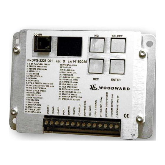
This manual provides information on the following DPG controllers: DPG-2223-001 and DPG-2223- 002. The DPG-2223-00X digital controller is used primarily to govern diesel or gas fueled engines of generator sets. This microprocessor-based, digital controller performs across a wide speed range and allows adjustment of all controller features through the built-in user interface. -
Page 10: Chapter 2. Controller Specifications
Released Manual 36522 DPG-2223-00X Controllers Chapter 2. Controller Specifications The controller’s main electrical and mechanical specifications are listed below along with several performance characteristics. Electrical Operating Voltage Range: 9–30 Vdc * Rated Output Current: 7 A Maximum (continuous) Maximum Surge Current:... -
Page 11: User Interface Operation
Released Manual 36522 DPG-2223-00X Controllers User Interface Operation The user interface has two distinct behaviors that you should familiarize yourself with in order to select parameters and adjust them. These behaviors are described in the Operating Modes section below. A 4-pushbutton keypad and a 2-digit LED display make up the built-in user interface. The pushbuttons, also called keys, are described in the section named Keypad. - Page 12 Released Manual 36522 DPG-2223-00X Controllers The selected parameter’s value cannot be modified; parameter editing is locked and values can only be viewed. This is the case when password protection is active and the unlock code has not been entered. Read about the Password parameter in the Parameter Reference chapter for more information about using password protection.
-
Page 13: Keypad
Released Manual 36522 DPG-2223-00X Controllers Keypad The keypad consists of four pushbuttons named ENTER, SELECT, INC, and DEC. ENTER Key The ENTER key is used to exit PARAMETER EDIT MODE and return to PARAMETER SELECT MODE while saving the parameter’s new value to nonvolatile memory. Nonvolatile memory is where parameter values are stored so that they are remembered even when the controller is not being powered. -
Page 14: Led Display
Released Manual 36522 DPG-2223-00X Controllers Press and hold both INC and DEC simultaneously to view the value of a 4-digit number’s upper two digits. Note that the left digit’s decimal point is turned on to indicate that the thousands and the hundreds digits are being displayed. - Page 15 Released Manual 36522 DPG-2223-00X Controllers An underflow occurs when the value 00 is displayed and the DEC key is pressed (assuming this is not the parameter’s minimum value). This will cause the displayed value to become 99 while the non- displayed value in the parameter’s upper 2 digits will be decreased by one.
-
Page 16: Chapter 3. Parameter Reference
Released Manual 36522 DPG-2223-00X Controllers Chapter 3. Parameter Reference This chapter provides information regarding each parameter’s function. Each of this chapter’s subsections provides information about a single parameter. Subsection numbering corresponds to the parameter numbering on the controller’s label to make it easier to locate information about the parameter of interest. -
Page 17: Parameter List
Released Manual 36522 DPG-2223-00X Controllers Parameter List DPG-2223-00X PARAMETER NAME DEFAULT MINIMUM MAXIMUM -001 1. No. of Flywheel Teeth -002 2. Remote Speed Min 1000 Remote Speed Max 1000 Remote Speed Min 11,000 3. Remote Speed Max 1000 Set Speed A Min Set Speed A Max 4. - Page 18 Released Manual 36522 DPG-2223-00X Controllers No. of Flywheel Teeth (optional) This parameter provides the conversion factor needed by the controller to display speeds as RPM values instead of Hertz values. Adjusting this parameter is optional. To use this parameter correctly, you must know the exact number of flywheel teeth that pass by the magnetic pickup in one revolution of the engine.
- Page 19 Released Manual 36522 DPG-2223-00X Controllers Remote Speed Min (optional) REMOTE SPEED MIN is the controller’s minimum target speed when the Remote Speed Pot is selected. The controller will read the remote speed pot position when the SPEED SEL input is OPEN and the startup sequence is complete.
- Page 20 Integral (required) The integral term is one of the interrelated PID terms that determine how well a DPG-2223-00X controller governs the engine’s speed. The integral term acts to drive speed error to zero. In a proportional only control with...
- Page 21 Released Manual 36522 DPG-2223-00X Controllers Derivative (required) The derivative term is one of the interrelated PID terms that determine how well a DPG- 2223-00X controller governs the engine’s speed. The derivative responds to the rate of change in the speed error. This parameter is primarily used to dampen very rapid oscillations resulting from large speed changes.
- Page 22 Released Manual 36522 DPG-2223-00X Controllers This parameter indicates the number of flywheel teeth to use when computing an average engine speed and is used to dampen out speed measurement variations that can make PID tuning difficult. But, keep in mind the following.
- Page 23 Released Manual 36522 DPG-2223-00X Controllers following formula determines the value needed by Decel Rate to decrease the engine speed from Set Speed A to Remote Speed in 1.5 seconds. [(Set Speed A) – (Remote Speed)] / (N seconds) = decel_rate_value in Hertz per second [4170 –...
- Page 24 Released Manual 36522 DPG-2223-00X Controllers NOTE: If the value is set too low the engine may not start. 3.20 Torque Limit (optional The torque limit parameter is used to limit the fuel supplied to the engine during heavy generator loads or generator overloads. The default value of 1000 allows the actuator drive signal to use 100.0% of available current.
- Page 25 Released Manual 36522 DPG-2223-00X Controllers 3.23 Percent Droop (optional) The percent droop parameter is used to select droop mode operation and specify the percentage of droop required. When the percent droop parameter is set to zero (the default setting) then droop mode is not active.
- Page 26 Released Manual 36522 DPG-2223-00X Controllers • entering calibration modes (see Calibration Instructions) Password protection is provided to guard against inadvertent parameter changes that may occur whenever the keys are pressed and a parameter modification is not intended. The password protection has three possible settings: DISABLED, LOCKED, and UNLOCKED. These settings can be modified with built-in user interface only (not Universal PST).
- Page 27 Released Manual 36522 DPG-2223-00X Controllers 3.29 Set Speed A Max (optional) Set Speed A Max is used to set the highest value allowed for adjustments of Set Speed A. This parameter can be set to any value within the range bordered by current Set Speed A setting and 11,000 Hertz (or its RPM equivalent).
- Page 28 Released Manual 36522 DPG-2223-00X Controllers whether the engine is cranking or running whenever an engine speed signal is present. See the “Startup Sequence” example in Chapter 5. If the Startup Speed value is set too low (less than crank speed) the controller’s target speed will be ramped to the active set speed (Idle, Remote Speed, or Set Speed A) before the engine has started.
- Page 29 DPG-2223-00X Controllers REMOTE SET SPEED PEDAL ACTION SETTING DIRECTION INPUT VOLTAGE 0 = Forward Acting Increase 1 = Reverse Acting Decrease The DPG-2223-00X defaults to forward acting mode. NOTE: This parameter is automatically set during Remote Speed Potentiometer Calibration Procedure. Woodward...
-
Page 30: Chapter 4. Universal Pst
Only trained personnel should have access to these tools. Acquiring Universal PST The Universal PST software can be downloaded from the Woodward website. If you also require connection hardware you may purchase a calibration kit from Woodward. Both download and kit request instructions are described below. - Page 31 NOTE: Due to the large file size, it is recommended that the [Open] button not be used because this would try to run the self-extracting executable from the web site. Installing Universal PST After downloading the software file from the Woodward web site, run it and follow the installer instructions. IMPORTANT: The installation program will detect operating system components older than those required by the "Universal PST"...
- Page 32 Released Manual 36522 DPG-2223-00X Controllers NOTE: Administrator rights may be needed to install on some Microsoft Windows operating systems (such as Windows XP Professional) for the setup program to properly register application resources. Wiring the COMM Port to a PC To construct a communications cable to use between the DPG’s COMM port and your PC’s RS-232...
- Page 33 Released Manual 36522 DPG-2223-00X Controllers TABLE VIEW In Table View the user can: • View the current values for all user programmable parameters in the Parameter Setup panel. • Edit a parameter’s value by double-clicking on a cell in the “Value” column of the table.
- Page 34 Select the PC’s serial port that is connected to the DPG-2223-00X Use the Help menu to access: • Help on the Universal PST for DPG • Help on the DPG-2223-00X that is currently in communication with the PC • Information about the Universal PST for DPG application Parameter Setup...
- Page 35 Released Manual 36522 DPG-2223-00X Controllers Synchronizing Universal PST with a DPG Pressing the <Read All> button will load the current values for all of a DPG- 2XXX-00X’s parameters into Universal PST. The <Read All> button is part of the Table View.
- Page 36 Released Manual 36522 DPG-2223-00X Controllers The Horizontal Scale options allow you to set how much data is displayed in the chart recorder window. Larger values compress the display and show more data. Smaller numbers expand the display and show less data. A Horizontal Scale setting of 20 seconds is approximately the same as a 5- millimeter per second paper travel speed of a conventional paper tape chart recorder.
-
Page 37: Chapter 5. Calibration Instructions
Released Manual 36522 DPG-2223-00X Controllers Chapter 5. Calibration Instructions Basic Adjustments The controller is programmed at the factory with default parameter settings. These settings allow the controller to operate but usually require some further adjustments to obtain the best system performance. -
Page 38: Droop Calibration Procedure
Released Manual 36522 DPG-2223-00X Controllers Note that without integral, a speed error may persist after a load-on load-off transition. Therefore, during steps 3-5 you should temporarily increase the integral to get the engine speed back to the set speed, and then reset the integral to a lower value again while working to find good proportional and derivative values. -
Page 39: Remote Speed Potentiometer Calibration Procedure
Released Manual 36522 DPG-2223-00X Controllers User Interface: Select the "FULL LOAD CAL" parameter. Engine speed will return to the selected set speed. Step 5 Universal PST: Proceed to Step 6. Now apply full load to the engine and allow the speed to stabilize. -
Page 40: Startup Sequence
DPG-2223-00X Controllers Startup Sequence The following example describes the DPG-2223-00X startup sequence. Engine cranking begins at point A. After a short time, the engine starts and at point B the engine speed exceeds the STARTUP SPEED (the initial target speed) and the controller now considers the engine to be running. -
Page 41: Chapter 6
+ 5 V Recommended Mounting The DPG-2223-00X controller is designed to be panel mounted and its chassis electrically bonded to the same protective reference as the engine structure. The mounting should protect the controller from exposure to rain, weather, and direct sunlight. The controller should not be mounted on the engine or in an environment that exceeds the mechanical specifications outlined in Chapter 2. -
Page 42: Centralized Suppression
S E T S P E E D A S E L E C T Figure 6-1. Wiring Diagram for DPG-2223-00X Models To prevent damage to the controller, make sure that it is wired in accordance with the wiring instructions and diagrams in this manual. - Page 43 Suppression kits available from Woodward are intended to suppress the majority of the likely pulses. However, they will not protect against all system level implementations outside the intended usage of the control.
-
Page 44: Chapter 7
Released Manual 36522 DPG-2223-00X Controllers Chapter 7. Diagnostics & Troubleshooting Display Codes Table 7-1. Display Codes CODE MEANING Controller memory failure. Replace controller. Loss of remote speed potentiometer signal. Overspeed detected. Controller must be turned off and reset to allow an engine restart. - Page 45 Released Manual 36522 DPG-2223-00X Controllers Improve PID tuning. Integral too low or zero Derivative too low or zero PID values are too low. A tuning that is too soft can prevent the controller from delivering the needed actuator drive signal to reach the set speed.
- Page 46 Released Manual 36522 DPG-2223-00X Controllers Improve PID tuning. Engine Instability With Fuel is restricted. Check Load actuator linkage. Battery voltage is too low. PID values may be too high, causing the controller Engine Unable to Carry to overreact and make...
-
Page 47: Chapter 8. Product Support And Service Options
Packager at their factory. In some cases, the programming is password-protected by the OEM or packager, and they are the best source for product service and support. Warranty service for Woodward products shipped with an equipment system should also be handled through the OEM or Packager. -
Page 48: Returning Equipment For Repair
All repair work carries the standard Woodward service warranty (Woodward Product and Service Warranty 5-09-0690) on replaced parts and labor. -
Page 49: Replacement Parts
• The unit serial number, which is also on the nameplate Engineering Services Woodward offers various Engineering Services for our products. For these services, you can contact us by telephone, by email, or through the Woodward website. • Technical Support •... -
Page 50: Technical Assistance
Technical Assistance If you need to contact technical assistance, you will need to provide the following information. Please write it down here before contacting the Engine OEM, the Packager, a Woodward Business Partner, or the Woodward factory: General Your Name... -
Page 51: Revision History
Released Manual 36522 DPG-2223-00X Controllers Revision History Changes in Revision H— • Removed EPG actuators from Actuator Compatibility section in Chapter 1 Woodward... -
Page 52: Declarations
Released Manual 36522 DPG-2223-00X Controllers Declarations Woodward... - Page 53 Email and Website—www.woodward.com Woodward has company-owned plants, subsidiaries, and branches, as well as authorized distributors and other authorized service and sales facilities throughout the world. Complete address / phone / fax / email information for all locations is available on our website.
Need help?
Do you have a question about the DPG-2223-00X and is the answer not in the manual?
Questions and answers