
Subscribe to Our Youtube Channel
Related Manuals for Woodward DPG-2111-001


Summary of Contents for Woodward DPG-2111-001
- Page 1 Released Product Manual 36536 (Revision C, 01/2024) Original Instructions DPG-2111-001 Digital Controller Programmable Controller for Isochronous Generators Installation and Operation Manual...
- Page 2 Revisions— A bold, black line alongside the text identifies changes in this publication since the last revision. Woodward reserves the right to update any portion of this publication at any time. Information provided by Woodward is believed to be correct and reliable. However, no responsibility is assumed by Woodward unless otherwise expressly undertaken.
-
Page 3: Table Of Contents
Engineering Services ..........................40 Contacting Woodward’s Support Organization ..................40 ........................41 EVISION ISTORY ........................42 ECLARATIONS The following are trademarks of Woodward, Inc.: • DPG 2111-XXX The following are trademarks of their respective companies: • Windows (Microsoft Corporation) • Pentium (Intel Corporation) - Page 4 Table 2-1. Electrical Specifications ....................... 8 Table 2-2. Mechanical Specifications ......................8 Table 2-3. Performance Specifications ......................8 Table 3-1. Parameter List for DPG-2111-001 ..................... 10 Table 4-1. Wiring the Comm Port to a PC ....................21 Table 5-1. Preliminary Tuning Parameters ....................29 Table 6-1 Terminal Functions ........................
-
Page 5: Warnings And Notices
Released Manual 36536 DPG-2111-001 Digital Controller Warnings and Notices Important Definitions This is the safety alert symbol used to alert you to potential personal injury hazards. Obey all safety messages that follow this symbol to avoid possible injury or death. - Page 6 Released Manual 36536 DPG-2111-001 Digital Controller On- and Off-highway Mobile Applications: Unless Woodward's control functions as the supervisory control, customer should install a system totally independent of the prime mover control system that monitors for supervisory control of engine (and takes appropriate...
-
Page 7: Electrostatic Discharge Awareness
Do not touch the components or conductors on a printed circuit board with your hands or with conductive devices. To prevent damage to electronic components caused by improper handling, read and observe the precautions in Woodward manual 82715 , Guide for Handling and Protection of Electronic Controls, Printed Circuit Boards, and Modules. -
Page 8: Regulatory Compliance
Released Manual 36536 DPG-2111-001 Digital Controller Regulatory Compliance EMC Limitations Cabling All cabling for this unit is limited to less than 30m (98.4’). See wiring diagrams for specific cable types required. Power cabling is limited to less than 10m (32.8’) in total length from its source; power is intended to be from a local bus structure. -
Page 9: Chapter 1. General Information
General Information Introduction The DPG-2111-001 digital controller is used primarily to govern diesel or gas fueled engines of generator sets. This microprocessor based, digital controller performs across a wide speed range and allows adjustment of the set speed and gain parameters with the built-in user interface. The COMM port provides access to all other controller settings, allowing adaptation to each application during service and initial configuration. -
Page 10: Chapter 2. Specifications
Released Manual 36536 DPG-2111-001 Digital Controller Chapter 2. Specifications The controller’s main electrical and mechanical specifications are listed below along with several performance characteristics. Table 2-1. Electrical Specifications Operating Voltage Range 9–30 Vdc Rated Output Current 7 A Maximum (continuous) -
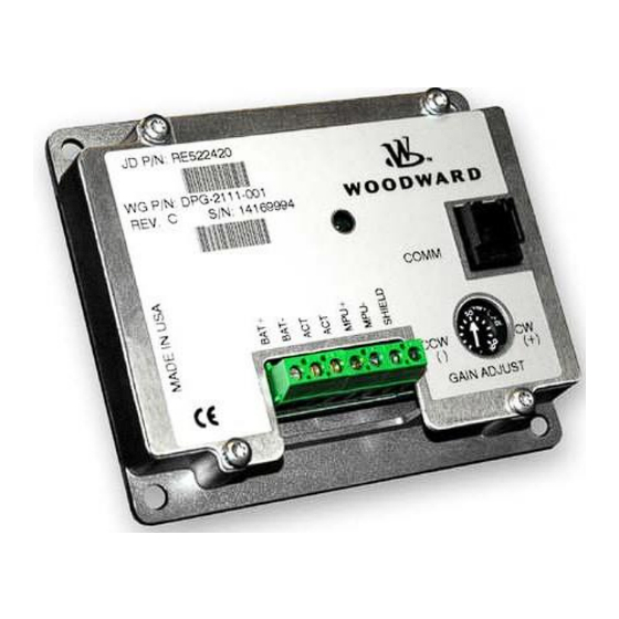
Page 11: User Interface Operation
User Interface Operation Gain Potentiometer The DPG-2111-001 controller provides a potentiometer (labeled GAIN) to adjust the OVG @ Set Speed A. This is one of the controller’s tuning parameters. The gain potentiometer adjustment range is +/-20% on the nominal value entered for the OVG @ Set Speed A parameter. -
Page 12: Chapter 3. Parameter Reference
Speed and Rate values are shown as Hertz values. Parameters in boldface (2, 5, 6, 7, 8, 11, 12, and 28) require adjustment, while adjustments to the other parameters are optional. Table 3-1. Parameter List for DPG-2111-001 Parameter Name Default Minimum Maximum —... -
Page 13: Parameter Functions
Released Manual 36536 DPG-2111-001 Digital Controller Table 3-1. Parameter List for DPG-2111-001 (cont’d.) Parameter Name Default Minimum Maximum — Not Available — Not Available Idle Speed Min Idle Speed Idle Speed Max 11000 Idle Speed 11000 Duty Cycle Limit Startup Speed... -
Page 14: Figure 3-1. Output Response To A Step Change In Speed Error
Released Manual 36536 DPG-2111-001 Digital Controller 3.5 Proportional (required) The proportional term is one of the interrelated PID terms that determine how well a DPG controller governs the engine’s speed. A speed change creates a speed error (the difference between the target speed and the actual speed.) The proportional gain controls the size of the controller output response to a... -
Page 15: Figure 3-3. Derivative Response To Engine Acceleration Or Deceleration
Released Manual 36536 DPG-2111-001 Digital Controller 3.7 Derivative (required) The derivative term is one of the interrelated PID terms that determine how well a DPG controller governs the engine’s speed. The derivative responds to the rate of change in the speed error. This parameter is primarily used to dampen very rapid oscillations resulting from large speed changes. - Page 16 Released Manual 36536 DPG-2111-001 Digital Controller For example, if the PID terms are set to 90, 80, and 50 respectively and the Gain Factor is set to 20, then doubling the Gain Factor by setting it to 40 allows the PID terms to be halved to 45, 40, and 25 respectively.
- Page 17 Released Manual 36536 DPG-2111-001 Digital Controller 3.15 Decel Rate (optional) The Decel Rate specifies how fast the controller should decrease the engine’s speed when a new lower target speed is made active. The parameter value is specified inHertz per second based on the following formula.
- Page 18 Released Manual 36536 DPG-2111-001 Digital Controller 3.18 Integral High Limit (optional) The integral high limit prevents "integral windup" in the positive direction. In other words, the integral high limit parameter is used to reduce overspeed duration after a long or sustained under speed condition was present.
- Page 19 Released Manual 36536 DPG-2111-001 Digital Controller 3.23 SET SPEED B MIN (not available) 3.24 SET SPEED B MAX (not available) 3.25 Idle Speed Min (optional) Idle Speed Min is used to set the lowest value allowed for Idle Speed adjustments. The adjustable range for Idle Speed Min extends from 10 Hertz to the current value of Idle Speed.
- Page 20 Released Manual 36536 DPG-2111-001 Digital Controller 3.29 Startup Duty Cycle (optional) The Startup Duty Cycle parameter is used to pre-load the PID output with a PWM duty cycle value close to that needed for the actuator to allow enough fuel to idle the engine.
-
Page 21: Chapter 4. Universal Pst
Only trained personnel should have access to these tools. Acquiring Universal PST The Universal PST software can be downloaded from the Woodward website. If you also require connection hardware you may purchase a calibration kit from Woodward. Both download and kit request instructions are described below. -
Page 22: Installing Universal Pst
Download the newest Universal PST version from the search results. You will be asked to log in to Woodward’s website if you haven’t already done so. After login, you will see the File Download dialog box shown below, or one similar. Click the [Save] button and choose a folder to save the download to. -
Page 23: Figure 4-1. Wiring Diagram
Released Manual 36536 DPG-2111-001 Digital Controller Wiring the COMM Port to a PC To construct a communications cable to use between the DPG’s COMM port and your PC’s RS-232 serial port refer to the table and wiring diagram below. Table 4-1. Wiring the Comm Port to a PC... -
Page 24: Universal Pst User Interface Overview
Released Manual 36536 DPG-2111-001 Digital Controller Communications Error The following message window appears when Universal PST is running and unable to communicate with a DPG. After the problem is found and corrected, you can either restart Universal PST or press the <Read All>... -
Page 25: Figure 4-3. Chart View Screen
Released Manual 36536 DPG-2111-001 Digital Controller Chart View Figure 4-3. Chart View Screen In Chart View the user can: • Monitor engine speed in real-time. • Adjust the horizontal and vertical scale settings of the chart recorder. • Edit parameter values related to controller tuning. These same parameters are also on the main parameter setup table. -
Page 26: Universal Pst Menu Items
Released Manual 36536 DPG-2111-001 Digital Controller Universal PST Menu Items Use the File Menu to: • Open a previously saved setup data file • Save setup data to a file • Send setup data to the default printer • Exit the program Figure 4-4. -
Page 27: Parameter Setup
Released Manual 36536 DPG-2111-001 Digital Controller Parameter Setup The Parameter Setup panel displays a table where each row shows the Name of a user programmable parameter, its current Value, and the parameter’s Default, Minimum, and Maximum values. To modify a parameter’s current value, it must first be selected. Do this by double-clicking the left mouse button on a cell in the table that is at the intersection of the parameter’s row and the Value column. -
Page 28: Figure 4-9. Status View Panel
Released Manual 36536 DPG-2111-001 Digital Controller Status View The Status View panel is displayed only after pressing the <View Status> button. The Status View panel is part of the Table View display mode. The Status View panel displays a table where each row shows the Name of a read only parameter and its current Value (when “Auto Read is ON”) -
Page 29: Figure 4-11. Chart Recorder Panel
Released Manual 36536 DPG-2111-001 Digital Controller Chart Recorder The chart recorder is part of the Chart View display mode. Each time Chart View is entered the last used Data File is reset, the Vertical Scale defaults to [0 Hz to 12000 Hz], and the Horizontal scale defaults to 20 seconds. - Page 30 Released Manual 36536 DPG-2111-001 Digital Controller The <Data File => button opens a dialog box allowing you to set the base file name where chart recorder data will be saved. A two-digit suffix is automatically appended to the file name that is given and serves the following purpose.
-
Page 31: Chapter 5. Calibration
Released Manual 36536 DPG-2111-001 Digital Controller Chapter 5. Calibration Basic Adjustments The controller is programmed at the factory with default parameter settings. These settings allow the controller to operate but usually require some further adjustments to obtain the best system performance. -
Page 32: Startup Sequence
Figure 5-1. PID Response to Errors Startup Sequence The following example describes the DPG-2111-001 startup sequence. Engine cranking begins at point A. After a short time, the engine starts and at point B the engine speed exceeds the STARTUP SPEED (the initial target speed) and the controller now considers the engine to be running. -
Page 33: Figure 5-2. Startup Sequence
Released Manual 36536 DPG-2111-001 Digital Controller Startup Sequence Example 3500 3000 IDLE HOLD SET SPEED A = 3500 Hz TIME = 100 2500 IDLE SPEED = 1500 Hz 2000 ACCEL RATE = 500 Hz/sec 1500 STARTUP RATE = 250 Hz/sec... -
Page 34: Chapter 6. Installation
Installation Recommended Mounting The DPG-2111-001 controller is designed to be panel mounted and its chassis electrically bonded to the same protective reference as the engine structure. The mounting location should protect the controller from exposure to rain, weather, and direct sunlight. The controller should not be mounted on the engine or in an environment that exceeds the mechanical specifications outlined in Chapter 2 of this manual. -
Page 35: Figure 6-1. Wiring Diagram For Dpg-2111- 001 Controller
Released Manual 36536 DPG-2111-001 Digital Controller Dimensions are in inches. [Dimensions in brackets are millimeters.] Figure 6-1. Wiring Diagram for DPG-2111- 001 Controller To prevent damage to the controller, make sure that it is wired in accordance with the wiring instructions and diagrams in this manual. -
Page 36: Centralized Suppression
Released Manual 36536 DPG-2111-001 Digital Controller Centralized Suppression The control meets the regulatory requirements for its intended installations, and when installed correctly as directed, the DPG input power can handle some level of surge pulses. Because the control power input is designed to be connected to a local bus and to have inductive load kickbacks suppressed, it cannot withstand a charging system load dump, heavy inductive kickbacks, or heavy surge pulses. -
Page 37: Figure 6-2. Centralized Suppression Implemented At The System Level
4. Suppression kits available from Woodward are intended to suppress the majority of the likely pulses. However, they will not protect against all system level implementations outside the intended usage of the control. -
Page 38: Chapter 7. Diagnostics & Troubleshooting
Released Manual 36536 DPG-2111-001 Digital Controller Chapter 7. Diagnostics & Troubleshooting Table 7-1. LED Indications LED State Meaning Controller is either not currently powered or is being reverse powered. (Check polarity of supplied power.) If correctly powered, then controller is malfunctioning. - Page 39 Released Manual 36536 DPG-2111-001 Digital Controller Table 7-2. Troubleshooting Chart (cont’d.) Symptom Solution Engine Does Not Reach Improve PID tuning. Set Speed Integral too low or zero. PID values are too low. A tuning that is too soft can prevent the controller from delivering the needed actuator drive signal to reach the set speed.
-
Page 40: Chapter 8. Product Support And Service Options
• An Authorized Independent Service Facility (AISF) provides authorized service that includes repairs, repair parts, and warranty service on Woodward's behalf. Service (not new unit sales) is an AISF's primary mission. A current list of Woodward Business Partners is available at www.woodward.com/local-partner... -
Page 41: Returning Equipment For Repair
All repair work carries the standard Woodward service warranty (Woodward Product and Service Warranty 5-09-0690) on replaced parts and labor. -
Page 42: Replacement Parts
• The unit serial number, which is also on the nameplate Engineering Services Woodward offers various Engineering Services for our products. For these services, you can contact us by telephone, by email, or through the Woodward website. • Technical Support •... -
Page 43: Revision History
Released Manual 36536 DPG-2111-001 Digital Controller Revision History Changes in Revision C— • Removed EPG 512 and EPG 1724 from Table 1-1 • Added Lockout/Tagout and IOLOCK warnings (pages 3 & 4) • Updated Electrostatic Discharge Awareness section (page 5) •... -
Page 44: Declarations
Released Manual 36536 DPG-2111-001 Digital Controller Declarations Woodward... - Page 45 Released Manual 36536 DPG-2111-001 Digital Controller THIS PAGE INTENTIONALLY LEFT BLANK Woodward...
- Page 46 Email and Website—www.woodward.com Woodward has company-owned plants, subsidiaries, and branches, as well as authorized distributors and other authorized service and sales facilities throughout the world. Complete address / phone / fax / email information for all locations is available on our website.
Need help?
Do you have a question about the DPG-2111-001 and is the answer not in the manual?
Questions and answers