Woodward DTSC-200A Operation
Ats controller
Hide thumbs
Also See for DTSC-200A:
- Installation manual (38 pages) ,
- Application (21 pages) ,
- Installation manual (20 pages)

Subscribe to Our Youtube Channel
Related Manuals for Woodward DTSC-200A


Summary of Contents for Woodward DTSC-200A
- Page 1 37941A DTSC-200A ATS Controller - Operation Operation Release 1.0 - 0 Document ID: 37941, Revision A...
- Page 2 Provides other helpful information that does not fall under the warning or caution categories. Woodward reserves the right to update any portion of this publication at any time. Information provided by Woodward is believed to be correct and reliable. However, Woodward assumes no responsibility unless otherwise expressly undertaken.
-
Page 3: Table Of Contents
Manual 37941A DTSC-200A - ATS Controller - Operation Revision History Rev. Date Editor Changes 2022-31-03 1.0-0 - Based on DTSC-200 V2.0017 Content 1. G ..................5 HAPTER ENERAL NFORMATION Related Documents ..........................5 QR Code .............................5 2. N .................. 6 HAPTER... - Page 4 Manual 37941A DTSC-200A - ATS Controller - Operation Illustrations And Tables Illustrations Figure 2-1: Front panel and display ..............................6 Figure 2-2: Home Page explanation ..............................16 Figure 3-1: General ATS functionality - flowchart ..........................19 Figure 3-2: Limit switch monitoring - failure message ........................23 Tables Table 1-1: Manual - Overview ................................
-
Page 5: Chapter 1. General Information
Manual 37941A DTSC-200A - ATS Controller - Operation Chapter 1. General Information Related Documents ≡≡≡≡≡≡≡≡≡≡≡≡≡≡≡≡≡≡≡≡≡≡≡≡≡ Type English German DTSC-200A DTSC-200A - Installation 37939 DTSC-200A - Configuration 37940 this manual DTSC-200A - Operation 37941 DTSC-200A - Application 37942 DTSC-200A - Interfaces... -
Page 6: Chapter 2. Navigation / Operation
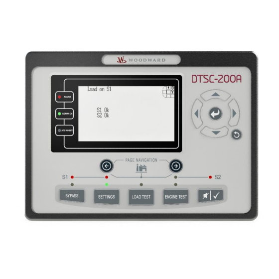
Manual 37941A DTSC-200A - ATS Controller - Operation Chapter 2. Navigation / Operation Figure 2-1: Front panel and display Figure 2-1 illustrates the front panel/display, which includes push buttons, LEDs and the Liquid Crystal display (LC display). A short description of the front panel is given below. - Page 7 Manual 37941A DTSC-200A - ATS Controller - Operation LED S2 ok The LED indicates that the source S2 is okay according to the configured operating ranges. LED Bypass possible The LED indicates that the current sequence timer is possible to be bypassed. The current se- quence timer is indicated on the Home Page View.
- Page 8 Manual 37941A DTSC-200A - ATS Controller - Operation Push Button LOAD TEST With this button the operator can manually initiate the LOAD TEST sequence. Once pushed he must confirm over display whether he want to start the LOAD TEST with all its consequences.
- Page 9 Manual 37941A DTSC-200A - ATS Controller - Operation Push Button ENGINE TEST With this button the operator can manually initiate the ENGINE TEST sequence. Once pushed he must confirm over display whether he want to start the ENGINE TEST [No Load Test] with all its consequences.
- Page 10 Manual 37941A DTSC-200A - ATS Controller - Operation Push button Acknowledge The acknowledge button has two functions: 1. If the Horn or a new alarm occurs the flashing LED Alarm is disabled until a next alarm takes place. 2. The single alarms can be acknowledged as long they are not active anymore.
- Page 11 Manual 37941A DTSC-200A - ATS Controller - Operation Navigation Button Overview The display contains on the top right corner a field which tells the operator which navigation buttons right to the display are currently active. Explanation: Requestion mark – Go into alarm list Tool –...
-
Page 12: Navigation
Manual 37941A DTSC-200A - ATS Controller - Operation Navigation ≡≡≡≡≡≡≡≡≡≡≡≡≡≡≡≡≡≡≡≡≡≡≡≡≡ Individual display screens are listed in the following text. All instruments, which are available in the individual screens, are described with their function. Screen "Automatic operation" / "Start screen" [all application modes]... - Page 13 Manual 37941A DTSC-200A - ATS Controller - Operation Screen "Source 1 values - Details" [all application modes] 1 / 2 / 3 ..Source 1 voltages/currents V/A / V/A / V/A 12 / 23 / 31 Source 1 voltages V 00.0V ..
- Page 14 Status display of the discrete inputs and discrete outputs. (Note: The configured logic for the discrete input "N.O./N.C." will deter- mine how the DTSC-200A reacts to the state of the discrete input. If the respective DI is configured to N.O, the unit reacts on the energized state ( );...
- Page 15 Manual 37941A DTSC-200A - ATS Controller - Operation Screen "LogicsManager Conditions" [all application modes] This screen shows in list form the LogicsManager groups. From there the operator can navigate to the according group of interest. Navigate to the LogicsManager conditions screens...
-
Page 16: Operation
Manual 37941A DTSC-200A - ATS Controller - Operation Operation ≡≡≡≡≡≡≡≡≡≡≡≡≡≡≡≡≡≡≡≡≡≡≡≡≡ The display is partitioned into different areas to give an overview of the displayed data. Information Text Field Event timer active Navigation Button Overview Timer Countdown Field Source Conditions Figure 2-2: Home Page explanation Operation Display "Operation"... -
Page 17: Timer Display
This means with pushing the indicated timer expires immediately and the unit proceeds with the next operation. Refer to Appendix A: Messages on page 33 for a list of the possible timers. LogicsManager Some parameters of the DTSC-200A are configured via the LogicsManager (refer to Configuration Manual 37940). A typical LogicsManager screen is shown in the following. - Page 18 Manual 37941A DTSC-200A - ATS Controller - Operation Select group of parameters By pressing this softkey character you may select the next group of LogicsManager rameter if you are on an LMCV parameter. Each time this softkey character is pressed, the next parameter group will be taken.
-
Page 19: Chapter 3. Functional Description
Manual 37941A DTSC-200A - ATS Controller - Operation Chapter 3. Functional Description General ATS Functionality ≡≡≡≡≡≡≡≡≡≡≡≡≡≡≡≡≡≡≡≡≡≡≡≡≡ The following flowchart shows the typical ATS functionality: Source 1 is Source 2 is powering the load available Close breaker to Source 1 Source 1... -
Page 20: Application Modes
Manual 37941A DTSC-200A - ATS Controller - Operation Application Modes ≡≡≡≡≡≡≡≡≡≡≡≡≡≡≡≡≡≡≡≡≡≡≡≡≡ The application mode may be configured in the unit (refer to the Configuration Manual 37940 for more infor- mation). This is only possible in code level 2. The most important features and differences of the three applica- tion modes are illustrated in the following section. -
Page 21: Blocking Transfer Operations
Manual 37941A DTSC-200A - ATS Controller - Operation Blocking Transfer Operations ≡≡≡≡≡≡≡≡≡≡≡≡≡≡≡≡≡≡≡≡≡≡≡≡≡ There are four cases that are able blocking ATS’ transfer operations: 1. LogicsManager function ‘Inhibit ATS’ LM 98.01 (see below) 2. LogicsManager function ‘Inhibit XFR to S1’ LM 98.02 3. - Page 22 Manual 37941A DTSC-200A - ATS Controller - Operation • Fail to close S1 is present • Fail to close S2 is present • Shunt trip enable flag (20.12) is enabled • The transfer switch is in S1 or S2 position AND...
-
Page 23: Limit Switch Monitoring (Mechanical Failure, Lm 21.11)
(C2, C1, C2O, C1O) is cur- rently being issued by the ATS controller. The DTSC-200A evaluates the currently present and with use limit switch open replies (parameter 3434) pre-selected replies from the ATS limit switch together with the currently available source to determine which reply signals are currently expected to be able to supply the load. -
Page 24: Table 3-1: Limit Switch Monitoring - Truth Table For "Standard" Limit Switch W/O "Open" Replies
Manual 37941A DTSC-200A - ATS Controller - Operation Truth Tables The truth tables indicate all possible reply signal combination conditions and the respective reactions of the ATS controller depending on the configuration of the parameters 3424 "Transfer switch type" and 3434 "Use limit sw. -
Page 25: Table 3-2: Limit Switch Monitoring - Truth Table For "Delayed" Limit Switch W/O "Open" Replies
Manual 37941A DTSC-200A - ATS Controller - Operation Table 3-2 is valid for the following settings: • Parameter 3424 "Transfer switch type" is configured to "Delayed" • Parameter 3434 "Use limit sw. OPEN replies" is configured to "NO" S1 preferred 98.11 LM:... - Page 26 Manual 37941A DTSC-200A - ATS Controller - Operation S1 preferred S1 source S2 source 98.11 LM: S1 closed signal S2 closed signal S1 open signal S2 open signal Actual Expected S1 Priority LM 19.01 LM 19.11 S1 S1O S2 S1O...
-
Page 27: Table 3-3: Limit Switch Monitoring - Truth Table For "Open" Limit Switch With "Open" Replies
Manual 37941A DTSC-200A - ATS Controller - Operation S1 preferred S1 source S2 source 98.11 LM: S1 closed signal S2 closed signal S1 open signal S2 open signal Actual Expected S1 Priority LM 19.01 LM 19.11 S1 S1O S2O S1 S2O... -
Page 28: Chapter 4. Configuration
Manual 37941A DTSC-200A - ATS Controller - Operation Chapter 4. Configuration This chapter provides information "how to configure the unit via the LC display" as well as the description of all parameters that may be changed without a password. If you have the correct passwords to access all code levels in order configure the unit, refer to manual 37940 for a description of all parameters, their setting range, and their influence to the operation of the unit. - Page 29 Manual 37941A DTSC-200A - ATS Controller - Operation Access configuration menus By pressing the SETTING button, the main menu of the con- figuration will be displayed. A flashing LED over the button additionally signals that the controller screen is in a settings screen.
-
Page 30: Parameters
Manual 37941A DTSC-200A - ATS Controller - Operation Parameters ≡≡≡≡≡≡≡≡≡≡≡≡≡≡≡≡≡≡≡≡≡≡≡≡≡ NOTE Descriptions of all parameters, which may be edited/configured via the display, are described in manu- al 37940. Language Language Change language {Language} Language {Language} . The selection of a language will affect the following text in the control unit: •... -
Page 31: Code Levels
Manual 37941A DTSC-200A - ATS Controller - Operation Code Levels Code level display Code level via display Info Codeebene Display This value displays the code level that is currently active for access via the front panel. Code level CAN port... -
Page 32: Real-Time Clock - Time
Manual 37941A DTSC-200A - ATS Controller - Operation Real-Time Clock - Time Hour Adjust clock time: hour 0 to 23 Stunden The hour of the current time is set here. Example: 0 ....0 hour of the day. 23 ....23 hour of the day. -
Page 33: Appendix A. Messages
Manual 37941A DTSC-200A - ATS Controller - Operation Appendix A. Messages Timer / Operation States ≡≡≡≡≡≡≡≡≡≡≡≡≡≡≡≡≡≡≡≡≡≡≡≡≡ The following table indicates the display messages of the various timers and operations states: Display text Description Corresponding timer parameter Note S1 Start delay Source 2 has failed, and now the S1 start delay timer is "S1 start delay time"... -
Page 34: Table 4-1: Timer / Operation States - Display
Manual 37941A DTSC-200A - ATS Controller - Operation Display text Description Corresponding timer parameter Note Inhib. XFR to S2 A transfer to Source 2 is inhibited although Source 2 is "Inhibit transfer to Source 2" available. In the case of a Source 1 failure, a transfer to activation via "Inhib. -
Page 35: Alarm Messages
Manual 37941A DTSC-200A - ATS Controller - Operation Alarm Messages ≡≡≡≡≡≡≡≡≡≡≡≡≡≡≡≡≡≡≡≡≡≡≡≡≡ Message in ToolKit Meaning Message in the display Batt.overvolt. Lev.1 Battery overvoltage, limit value 1 Batt.overvolt.1 The battery voltage has exceeded the limit value 1 for battery overvoltage for at least the configured time and did not fall below the value of the hysteresis. - Page 36 Manual 37941A DTSC-200A - ATS Controller - Operation Message in ToolKit Meaning Message in the display In-phase timeout Inphase timer has expired If inphase monitoring is enabled and the unit was not able to detect synchronism between source 1 and source 2 within the configured time, this message will be displayed.
- Page 37 Phone +49 (0) 711 789 54-510 • Fax +49 (0) 711 789 54-101 stgt-info@woodward.com Homepage http://www.woodward.com Woodward has company-owned plants, subsidiaries, and branches, as well as authorized distributors and other authorized service and sales facilities throughout the world. Complete address/phone/fax/e-mail information for all locations is available on our website (www.woodward.com).
Need help?
Do you have a question about the DTSC-200A and is the answer not in the manual?
Questions and answers