
Related Manuals for Woodward APECS DPG-2101-001


Summary of Contents for Woodward APECS DPG-2101-001
- Page 1 User Manual DPG-2101-001 DPG-2145-001 DPG-21XX-00X Digital Controllers ® APECS Programmable Controllers for Isochronous Generators Manual 36526A...
- Page 2 Revisions—Text changes are indicated by a black line alongside the text. Woodward Governor Company reserves the right to update any portion of this publication at any time. Information provided by Woodward Governor Company is believed to be correct and reliable.
-
Page 3: Table Of Contents
3.23 Set Speed B Min (optional)..............16 3.24 Set Speed B Max (optional)..............16 3.25 Idle Speed Min (optional)..............16 3.26 Idle Speed Max (optional)..............17 3.27 Duty Cycle Limit (optional)..............17 3.28 Startup Speed (optional)..............17 3.29 Startup Duty Cycle (optional).............. 18 Woodward... - Page 4 Flat Rate Repair................... 40 Flat Rate Remanufacture................40 Returning Equipment for Repair ................40 Packing a Control ..................40 Return Authorization Number ..............41 Replacement Parts ....................41 How to Contact Woodward.................. 41 Engineering Services................... 42 Technical Assistance................... 43 Woodward...
-
Page 5: Regulatory Compliance
Member States relating to electromagnetic compatibility. EMC Limitations All cabling for these controllers is limited to less than 30m (98.4’). Power cabling is limited to less than 10m (32.8’) in total length. See plant wiring diagrams for specific cable types required. Woodward... -
Page 6: Electrostatic Discharge Awareness
PCB from the control cabinet, place it in the anti- static protective bag. CAUTION To prevent damage to electronic components caused by improper handling, read and observe the precautions in Woodward manual 82715, Guide for Handling and Protection of Electronic Controls, Printed Circuit Boards, and Modules. Woodward... -
Page 7: Chapter 1. General Information
APECS 0250 DYNA 10141 DYNA 8400 APECS 0300 Power Flow Series Gas Valves APECS Linkage Free Integral Type Other Models Available: DPG-2100 Series – for Genset Applications DPG-2300 Series – for Off-Road Vehicles DPG-2400 Series – for EFC Valve Applications Woodward... -
Page 8: Chapter 2. Controller Specifications
See wiring diagrams for specific cable types required. Mechanical Ambient Operating Temperature: -40° F to +185° F (-40° C to +85° C) Oil, water, and dust resistant via Sealing: conformal coating and die cast enclosure Weight: 10 oz. (284 g) Woodward... -
Page 9: Performance
The LED (Light Emitting Diode) is used as a status indicator. When the LED is off, it indicates that one of the following is true: • The unit is not being powered. • The unit is reverse powered (check polarity of supplied power). Woodward... -
Page 10: Comm Port
It is a service port and not intended for permanent connection. The Universal PST is an MS Windows based application available from the Software Products page at www.woodward.com/IC/Software. See Chapter 4 for a description of this tool. Woodward... -
Page 11: Chapter 3. Parameter Reference
The following tables list each of the parameters and their default, minimum, and maximum values. Several of the parameters have minimum and maximum values set by other parameters. Speed and Rate values are shown as Hertz values. Woodward... -
Page 12: Dpg-2101-00X & Dpg-2146-00X Parameter List
DPG-2146-00X controller Note: All Speed and Rate values are shown as Hertz values (parameters 2, 4, 14-16, 20-22, 25-26). Changing the value of parameter 1 will cause different default values to be displayed based on the Hertz to RPM formula. Woodward... -
Page 13: Dpg-2155-00X & Dpg-2145-00X Parameter List
DPG-2145-00X controller. Note: All Speed and Rate values are shown as Hertz values (parameters 2-4, 14-16, 20-26). Changing the value of parameter 1 will cause different default values to be displayed based on the Hertz to RPM formula. Woodward... -
Page 14: Dpg-2111-00X Parameter List
Opt. = Parameter use is optional Note: All Speed and Rate values are shown as Hertz values (parameters 2, 4, 14-16, 20-22, 25-26). Changing the value of parameter 1 will cause different default values to be displayed based on the Hertz to RPM formula. Woodward... -
Page 15: No. Of Flywheel Teeth Or Pulses Per Revolution (Optional)
To refresh the value displayed on the PC the user must select a different parameter with the mouse pointer then reselect the value of Set Speed A. The Universal PST application also provides a [Read All] button that can be used to perform a complete refresh of all parameter values. Woodward... -
Page 16: Set Speed B (Optional)
SET SPEED A or SET SPEED B depending on the state of the SPEED SEL input terminal. The default value for IDLE SPEED is 500 MPU Hertz (20 Hertz ignition). The IDLE SPEED parameter’s adjustable range extends from IDLE SPEED MIN to IDLE SPEED MAX. Woodward... -
Page 17: Proportional (Required)
A zero value is allowed but systems When the "Rate of change" changes (red dot) the Derivative' s impact on controller output changes. typically require some derivative gain to improve overall engine speed control. Woodward... -
Page 18: Ovg @ Set Speed A (Required)
PID tuning difficult. But, keep in mind the following. • Too much filtering will slow down the controller’s response to speed changes. • Too little filtering can make the controller overly sensitive and tuning difficult. Woodward... -
Page 19: Idle Hold Time (Optional)
The Decel Rate specifies how fast the controller should decrease the engine’s speed when a new lower target speed is made active. The parameter value is specified in Hertz per second based on the following formula. [(higher_speed_in_Hertz) – (lower_speed_in_Hertz)] / (ramp_time_in_seconds) = decel_rate_value Woodward... -
Page 20: Startup Rate (Optional)
The integral low limit specifies the PWM duty cycle where the integrator’s influence on lowering PID output must stop. The default value is 0%. The value can be adjusted from 0% to 90% in 1% increments. Woodward... -
Page 21: Integral High Limit (Optional)
The parameter’s value is in terms of a percentage over the highest set speed. In other words, an over speed condition is detected if the engine speed reaches a speed of [OVER SPEED LIMIT %] greater than the highest set speed. Woodward... -
Page 22: Set Speed A Min (Optional)
3.25 Idle Speed Min (optional) Idle Speed Min is used to set the lowest value allowed for Idle Speed adjustments. The adjustable range for Idle Speed Min extends from 10 Hertz (2 Hertz ignition) to the current value of Idle Speed. Woodward... -
Page 23: Idle Speed Max (Optional)
2) Use a PC running the Universal PST application and read the value of the Measured Speed in the View Status panel when the engine is cranking. Note: From the Universal PST startup screen press the View Status button, then press the Start Monitoring button to begin reading values. Woodward... -
Page 24: Startup Duty Cycle (Optional)
2) Use a PC running the Universal PST application and read the value of the PWM command in the View Status panel when the engine is cranking. Note: from the Universal PST startup screen press the View Status button, then press the Start Monitoring button to begin reading values. Woodward... -
Page 25: Chapter 4. Universal Pst
Introduction The Universal Parameter Setup Tool (Universal PST) is a Microsoft® Windows® application available from Woodward that enables you to adjust controller parameter settings and monitor controller operation. Universal PST also includes a graphical chart recorder that displays engine speed in real-time. This provides a visual representation of how the engine speed changes in response to changes in load, which can be very helpful when tuning the controller. -
Page 26: Acquiring Universal Pst
Download to begin the download process. Once you are logged into the Woodward download site you are presented with the File Download dialog box shown below, or one similar. Click the [Save] button and choose a folder to save the download to. -
Page 27: Installing Universal Pst
CD then double click on the “setup.exe” file. Instructions to Install from the Downloaded File: The file downloaded from the Woodward web site contains two files: “ReadMeFirst.txt” and “setup.exe”. Run the downloaded file to extract its contents to a folder you choose on your computer’s hard drive. -
Page 28: Communications Error
• Press the <Read All> button to refresh the values displayed in the Parameter Setup panel. • Press the <Write All> button to transmit setup values to the controller. • Press the <View Status> button to display read only parameters in the Status View panel. Woodward... - Page 29 • Press the <View Table> button to set the display mode back to Table View. • Select items from the menu. NOTE: Pressing a button means positioning the mouse pointer over the button and clicking the left mouse button. Woodward...
-
Page 30: Universal Pst Menu Items
When done modifying the value, press the computer keyboard’s <Enter> key to transmit the new value to the controller. In the figure shown below, the Set Speed A value has been selected for editing. Woodward... -
Page 31: Parameter Help
Name of a read only parameter and its current Value (when “Auto Read is ON”) Press (left mouse click) the <START Monitoring> button to have the Universal PST program automatically refresh the Values. Press the <STOP Monitoring> button to disable automatic refresh. Woodward... -
Page 32: Tuning View
The Chart Recorder Signal Filtering options can be used to smooth out noisy signals. The default setting is Min, which is no filtering. Note that filtering will round out peaks and give a less accurate display of the speeds actually measured by the DPG. Woodward... -
Page 33: Engine Speed Data Collection
Use the <View Table> button to return to the Table View display mode. Be sure to open a new Data File before returning to Table View if the data already collected needs to be saved. The active data file is automatically reset each time the Chart View display mode becomes active. Woodward... -
Page 34: Chapter 5. Calibration Instructions
Add some integral to eliminate any steady-state error in the engine’s speed and help decrease error recovery time. The overall gain can be increased to improve response time while keeping the ratios of the PID terms relative to each other constant. Woodward... - Page 35 The Derivative works on the Instantaneous Rate of Change The Proportional in the amount of error term' s output is unique for each measured error Time Integration works on the sum of the errors accumulated over time Woodward...
-
Page 36: Chapter 6. Installation Instructions
Magnetic pickup ground SHIELD Ground connection for cable shielding DPG-2111-00X NAME FUNCTION BAT+ Battery positive (9–30 Vdc) BAT- Battery negative Actuator drive output Actuator drive return MPU+ Magnetic pickup signal input MPU- Magnetic pickup ground SHIELD Ground connection for cable shielding Woodward... -
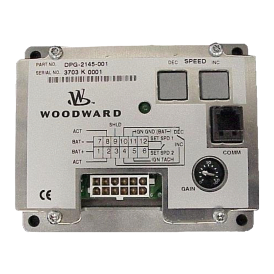
Page 37: Dpg-2145-00X
Battery negative Actuator drive return SHIELD Ground connection for cable shielding Digital input to decrease selected set speed (Active when tied to Pin 3) MPU- Magnetic pickup ground SET SPD 1 Set Speed A selected when this pin is open Woodward... -
Page 38: Wiring Diagrams
Figure 1. Wiring Diagram for DPG-2101-001 and DPG-2101-002 Controllers Connect the MPU shield at the controller end only. Connecting the shield at the MPU source end could introduce noise due to ground loops and also disable the reverse battery protection feature. Woodward... -
Page 39: Dpg-2111-00X
Figure 2. Wiring Diagram for DPG-2111-001 Controller Connect the MPU shield at the controller end only. Connecting the shield at the MPU source end could introduce noise due to ground loops and also disable the reverse battery protection feature. Woodward... -
Page 40: Dpg-2145-00X
Figure 3. Wiring Diagram for DPG-2145-001 and DPG 2145-002 Controllers Connect the MPU shield at the controller end only. Connecting the shield at the MPU source end could introduce noise due to ground loops and also disable the reverse battery protection feature. Woodward... -
Page 41: Dpg-2146-00X
Figure 4. Wiring Diagram for DPG-2146-001 and DPG-2146-002 Controllers Connect the MPU shield at the controller end only. Connecting the shield at the MPU source end could introduce noise due to ground loops and also disable the reverse battery protection feature. Woodward... -
Page 42: Dpg-2155-00X
Figure 5. Wiring Diagram for DPG-2155-001 and DPG-2155-002 Controllers Connect the MPU shield at the controller end only. Connecting the shield at the MPU source end could introduce noise due to ground loops and also disable the reverse battery protection feature. Woodward... -
Page 43: Chapter 7. Diagnostics & Troubleshooting
Final target speed must be greater than crank speed before the controller will attempt to drive the actuator open. Increase the Proportional value. Engine Overspeeds at Startup Increase the appropriate Gain value. Decrease the Startup Ramp Rate. Woodward... - Page 44 PID values may be too high, causing the controller to overreact and make large, rapid changes in PWM duty cycle Engine Unable to Carry output to the actuator. Rated Load Improve PID tuning. Fuel is restricted. Check actuator linkage. Woodward...
-
Page 45: Chapter 8. Service Options
If the core (field unit) is returned to Woodward within 60 days, Woodward will issue a credit for the core charge. [The core charge is the average difference between the flat rate replacement/exchange charge and the current list price of a new unit.]... -
Page 46: Flat Rate Repair
Warranty 5-01-1205). This option is applicable to mechanical products only. Returning Equipment for Repair If a control (or any part of an electronic control) is to be returned to Woodward for repair, please contact Woodward in advance to obtain a Return Authorization Number. -
Page 47: Return Authorization Number
DPG-21XX-00X Digital Controllers Return Authorization Number When returning equipment to Woodward, please telephone and ask for the Customer Service Department [1 (800) 523-2831 in North America or +1 (970) 482-5811]. They will help expedite the processing of your order through our distributors or local service facility. -
Page 48: Engineering Services
Manual 36526A DPG-21XX-00X Digital Controllers Engineering Services Woodward Industrial Controls Engineering Services offers the following after-sales support for Woodward products. For these services, you can contact us by telephone, by email, or through the Woodward website. • Technical Support •... -
Page 49: Technical Assistance
Type of Fuel (gas, gaseous, steam, etc) Rating Application Control/Governor Information Please list all Woodward governors, actuators, and electronic controls in your system: Woodward Part Number and Revision Letter Control Description or Governor Type Serial Number Woodward Part Number and Revision Letter... - Page 50 Phone +1 (970) 482-5811 • Fax +1 (970) 498-3058 Email and Website—www.woodward.com Woodward has company-owned plants, subsidiaries, and branches, as well as authorized distributors and other authorized service and sales facilities throughout the world. Complete address / phone / fax / email information for all locations is available on our website.
Need help?
Do you have a question about the APECS DPG-2101-001 and is the answer not in the manual?
Questions and answers