
Subscribe to Our Youtube Channel
Related Manuals for Woodward DPG-210X


Summary of Contents for Woodward DPG-210X
- Page 1 Released Product Manual 36543 (Revision C, 02/2024) Original Instructions DPG-210X Digital Controller Programmable Controller for Isochronous Generators Installation and Operation Manual...
- Page 2 Revisions— A bold, black line alongside the text identifies changes in this publication since the last revision. Woodward reserves the right to update any portion of this publication at any time. Information provided by Woodward is believed to be correct and reliable. However, no responsibility is assumed by Woodward unless otherwise expressly undertaken.
-
Page 3: Table Of Contents
Product Support Options ..........................19 Product Service Options ..........................19 Returning Equipment for Repair ........................20 Replacement Parts .............................21 Engineering Services ..........................21 Contacting Woodward’s Support Organization ..................21 ........................22 EVISION ISTORY ........................23 ECLARATIONS The following are trademarks of Woodward, Inc.: • DPG 210X Woodward... - Page 4 Manual 36543 DPG-210X Digital Controller Illustrations and Tables Figure 4-1. Wiring Diagram for DPG-210X Controllers ................14 Figure 4-2. Centralized Suppression Implemented at the System Level ............ 16 Table 1-1. Actuator Compatibility ........................7 Table 2-1. Electrical Specifications ....................... 8 Table 2-2.
-
Page 5: Warnings And Notices
Released Manual 36543 DPG-210X Digital Controller Warnings and Notices Important Definitions This is the safety alert symbol used to alert you to potential personal injury hazards. Obey all safety messages that follow this symbol to avoid possible injury or death. - Page 6 Released Manual 36543 DPG-210X Digital Controller On- and Off-highway Mobile Applications: Unless Woodward's control functions as the supervisory control, customer should install a system totally independent of the prime mover control system that monitors for supervisory control of engine (and takes appropriate...
-
Page 7: Electrostatic Discharge Awareness
Do not touch the components or conductors on a printed circuit board with your hands or with conductive devices. To prevent damage to electronic components caused by improper handling, read and observe the precautions in Woodward manual 82715 , Guide for Handling and Protection of Electronic Controls, Printed Circuit Boards, and Modules. -
Page 8: Regulatory Compliance
Released Manual 36543 DPG-210X Digital Controller Regulatory Compliance EMC Limitations Cabling All cabling for this unit is limited to less than 30m (98.4’). See wiring diagrams for specific cable types required. Power cabling is limited to less than 10m (32.8’) in total length from its source; power is intended to be from a local bus structure. -
Page 9: Chapter 1. General Information
General Information Introduction DPG-210X controllers can be used on both diesel and gas engines. They can operate over a frequency range of 1000 to 11,000 Hz, and over a nominal voltage range of 9 to 30 Vdc. Models in the series are DPG 2102, DPG-2103, DPG 2104, DPG-2105, and DPG 2107. -
Page 10: Chapter 2. Specifications
Released Manual 36543 DPG-210X Digital Controller Chapter 2. Specifications The controller’s main electrical and mechanical specifications are listed below along with several performance characteristics. Table 2-1. Electrical Specifications Operating Voltage Range 9–30 Vdc Rated Output Current 7 A Maximum (continuous) Maximum Surge Current 14 A (not to exceed ten seconds) Temperature Stability 0.007 Hz @ 158°F (70 °C) -
Page 11: User Interface Operation
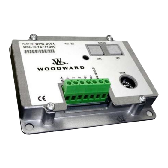
• INC – increases the Set Speed • DEC – decreases the Set Speed Gain Potentiometer The DPG-210X controller provides a potentiometer (labeled GAIN) for two separate adjustments: • Overall gain setting • Integral limit setting The LED (Light Emitting Diode) is used as a status and operating indicator. When the LED is off, it indicates that one of the following is true: •... -
Page 12: Chapter 3. Parameter Reference
Manual 36543 DPG-210X Digital Controller Chapter 3. Parameter Reference DPG-210X controllers have three user-adjustable parameters: Set Speed, Gain, and Integral Limit. Table 3-1 shows the factory, minimum, and maximum settings for these parameters. Table 3-1. DPG-210X Parameter Settings Parameter Factory Setting... -
Page 13: Adjusting Engine Set Speed And Gain Setting Together
Adjusting Engine Set Speed and Gain Setting Together The DPG-210X is a very versatile controller. The speed range is 1000 Hz to 11,000 Hz. The wide range of speed adjustment also has wide range of gain adjustments. The speed adjustment and gain adjustment ranges are in direct relationship with each other. -
Page 14: Integral Limit Setting
Released Manual 36543 DPG-210X Digital Controller Integral Limit Setting The INTEGRAL LIMIT is another adjustment that is available. The integral limit setting should only be adjusted when the engine is not running. The factory setting for the integral limit initially equals 75% (DPG- 2102, DPG-2103, DPG-2104), 76% (DPG-2105) or 50% (DPG-2107). -
Page 15: Chapter 4. Installation
Installation Recommended Mounting The DPG-210X controller is designed to be panel mounted and its chassis electrically bonded to the same protective reference as the engine structure. The mounting location should protect the controller from exposure to rain, weather, and direct sunlight. The controller should not be mounted on the engine or in an environment that exceeds the mechanical specifications outlined in Chapter 2 of this manual. - Page 16 DPG-210X Digital Controller Dimensions are in inches. [Dimensions in brackets are millimeters.] Figure 4-1. Wiring Diagram for DPG-210X Controllers To prevent damage to the controller, make sure that it is wired in accordance with the wiring instructions and diagrams in this manual.
-
Page 17: Centralized Suppression
Released Manual 36543 DPG-210X Digital Controller Centralized Suppression The control meets the regulatory requirements for its intended installations, and when installed correctly as directed, the DPG input power can handle some level of surge pulses. Because the control power input is designed to be connected to a local bus and to have inductive load kickbacks suppressed, it cannot withstand a charging system load dump, heavy inductive kickbacks, or heavy surge pulses. - Page 18 4. Suppression kits available from Woodward are intended to suppress the majority of the likely pulses. However, they will not protect against all system level implementations outside the intended usage of the control.
-
Page 19: Chapter 5. Diagnostics & Troubleshooting
Released Manual 36543 DPG-210X Digital Controller Chapter 5. Diagnostics & Troubleshooting Table 5-1. Troubleshooting Chart Symptom Detection Corrective Action System appears dead: No Check battery voltage at controller with If no voltage, check LED, fails to move power switch turned ON. Measure DC connections to battery. - Page 20 Released Manual 36543 DPG-210X Digital Controller Table 5-1. Troubleshooting Chart (cont’d.) Symptom Detection Corrective Action Engine hunts during operation. Linkage or rod end bearing Lubricate or replace (External linkage) sticking or binding. Improper linkage See installation chapter arrangement. (Stroke too short...
-
Page 21: Chapter 6. Product Support And Service Options
• An Authorized Independent Service Facility (AISF) provides authorized service that includes repairs, repair parts, and warranty service on Woodward's behalf. Service (not new unit sales) is an AISF's primary mission. A current list of Woodward Business Partners is available at www.woodward.com/local-partner... -
Page 22: Returning Equipment For Repair
All repair work carries the standard Woodward service warranty (Woodward Product and Service Warranty 5-09-0690) on replaced parts and labor. -
Page 23: Replacement Parts
• The unit serial number, which is also on the nameplate Engineering Services Woodward offers various Engineering Services for our products. For these services, you can contact us by telephone, by email, or through the Woodward website. • Technical Support •... -
Page 24: Revision History
Released Manual 36543 DPG-210X Digital Controller Revision History Changes in Revision C— • Removed EPG 512 and EPG 1724 from Table 1-1 • Added Lockout/Tagout and IOLOCK warnings (pages 3 & 4) • Updated Electrostatic Discharge Awareness section (page 5) •... -
Page 25: Declarations
Released Manual 36543 DPG-210X Digital Controller Declarations Woodward... - Page 26 Email and Website—www.woodward.com Woodward has company-owned plants, subsidiaries, and branches, as well as authorized distributors and other authorized service and sales facilities throughout the world. Complete address / phone / fax / email information for all locations is available on our website.
Need help?
Do you have a question about the DPG-210X and is the answer not in the manual?
Questions and answers