
Related Manuals for Woodward DSLC-2


Summary of Contents for Woodward DSLC-2
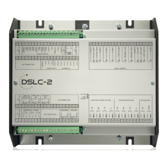
- Page 1 37443A DSLC-2 Digital Synchronizer and Load Control Manual Software Version 1.14xx Manual 37443A...
- Page 2 Provides other helpful information that does not fall under the warning or caution categories. Woodward reserves the right to update any portion of this publication at any time. Information provided by Woodward is believed to be correct and reliable. However, Woodward assumes no responsibility unless otherwise expressly undertaken.
-
Page 3: Table Of Contents
• 11-05-13 Minor corrections New features Requirements: Digital synchronizer and load control (DSLC-2)with software revision 1.1404 or higher and device revision A or higher. • Modbus communication: Loss of connection. Refer to “Loss Of Connection” on page 192 for details. - Page 4 Manual 37443A DSLC-2 - Digital Synchronizer and Load Control Menu (Setpoint) Description ........................57 DSLC-2 – Homepage ........................57 Menu 1 – Synchronizer ....................... 61 Menu 2 – Load Control ........................ 65 Menu 3 – Process Control ......................69 Menu 4 – Var / PF Control ......................71 Menu 5 –...
- Page 5 Manual 37443A DSLC-2 - Digital Synchronizer and Load Control 5. R .............. 160 HAPTER OWER ONTROL ESCRIPTION Introduction............................160 Power Management Concepts ......................160 Droop ............................160 Droop Tracking .......................... 161 Isochronous ..........................161 Droop/Isochronous Load Sharing On An Isolated Bus .............. 162 Isochronous Load Sharing On An Isolated Bus .................
- Page 6 Manual 37443A DSLC-2 - Digital Synchronizer and Load Control A. T .................... 201 PPENDIX ECHNICAL Environmental Data ..........................203 Accuracy .............................. 204 B. U ..................205 PPENDIX SEFUL NFORMATION Connecting 24 V Relays ......................205 C. D ..................206 PPENDIX ROTOCOLS Data Protocol 5200 ..........................
- Page 7 Figure 2-2: Housing - drill plan ..............................20 Figure 2-3: DSLC-2 - terminal arrangement ..........................21 Figure 2-4: Wiring diagram - DSLC-2 - 1/2 ..........................22 Figure 2-5: Wiring diagram - DSLC-2 - 2/2 ..........................23 Figure 2-6: Power supply ................................25 Figure 2-7: Power supply - crank waveform at maximum load ....................
- Page 8 Figure 9-1: Diagram frequency / active power controller ....................... 182 Figure 9-2: Diagram voltage / reactive power controller ......................183 Figure 10-1: DSLC-2 - interface overview (housing - side view) ................... 184 Figure 10-2: Modbus - visualization configurations ....................... 188 Figure 10-3: Modbus - sending binary digital orders over interface ..................
- Page 9 Table 3-29: Parameter – DSLC-2 overview page 1 ........................ 112 Table 3-30: Parameter – DSLC-2 overview page 2 ........................ 114 Table 3-30: Parameter – DSLC-2 overview page 3 – MSLC-2 ....................116 Table 4-1: Low voltage system 480 V / 277 V – 3-phase with neutral ................... 143 Table 4-2: Low voltage system 480 V / 277 V –...
- Page 10 Manual 37443A DSLC-2 - Digital Synchronizer and Load Control Table 10-11: Modbus – generator voltage measuring ......................197 Table 10-12: Modbus – reset default values ........................... 198 Table 10-13: Modbus - serial interface 1 - parameters ......................200 Table 10-14: Modbus - serial interface 2 – parameters ......................200 Table 10-15: Modbus - TCP/IP Network B–...
-
Page 11: Chapter 1. General Information
Manual 37443A DSLC-2 - Digital Synchronizer and Load Control Chapter 1. General Information Document Overview ≡≡≡≡≡≡≡≡≡≡≡≡≡≡≡≡≡≡≡≡≡≡≡≡≡ This manual describes the Woodward DSLC-2 Digital Synchronizer and Load Control. Type English German DSLC-2 this manual DSLC-2 – User Manual 37443 MSLC-2 – User Manual... -
Page 12: Application
The DSLC-2 control provides a safe automatic dead-bus closure function. Deadbus closing permission is granted to only one DSLC-2 or MSLC-2 control in the whole system, through locking techniques done over the communications network. This assures that a race condition will not cause two or more breakers to close simulta- neously on the dead bus. -
Page 13: Load Control
Load Control ≡≡≡≡≡≡≡≡≡≡≡≡≡≡≡≡≡≡≡≡≡≡≡≡≡ Load control begins at breaker closure when the load control function takes control of the DSLC-2 speed bias output directly from the synchronizer. The matching of synchronizer slip frequency to initial load (unload trip level) can result in a bumpless transfer to load control. On command, the adjustable ramp allows smooth, time- controlled loading into base load, isochronous load sharing or process control. -
Page 14: Process Control
The var/PF controller will limit the generators kvar output to the generator rated reactive power setpoint when connected to an infinite bus. A DSLC-2 must be in baseload or process control or a MSLC-2 must be in control. This will protect the generator when connected to an infinite source. This feature is not active when the DSLC-2 is in the load sharing mode (isolated). -
Page 15: Dslc-2 / Mslc-2 Systems
DSLC-2 / MSLC-2 Systems ≡≡≡≡≡≡≡≡≡≡≡≡≡≡≡≡≡≡≡≡≡≡≡≡≡ The network addressing of the DSLC-2 / MSLC-2 allows up to 32 DSLC-2s and 16 MSLC-2s in an application. A DSLC-2 and MSLC-2 application can handle 8 segments. Discrete inputs inform the DSLC-2s and MSLC-2s which segments each generator and utilities are operating on. -
Page 16: Figure 1-3: Multiple Generators In Isolated And Utility Parallel Operation With Utility- And Tie-Breaker
Manual 37443A DSLC-2 - Digital Synchronizer and Load Control Figure 1-3: Multiple generators in isolated and utility parallel operation with utility- and tie-breaker Page 16/226 © Woodward... -
Page 17: Chapter 2. Installation
CAUTION To prevent damage to electronic components caused by improper handling, read and observe the pre- cautions in Woodward manual 82715, Guide for Handling and Protection of Electronic Controls, Printed Circuit Boards and Modules. NOTE The unit is capable to withstand an electrostatic powder coating process with a voltage of up to 85 kV and a current of up to 40 µA. -
Page 18: Unpacking
Protect the unit from direct exposure to water or to a condensation-prone environment. • The continuous operating range of the DSLC-2 control is –40 to +70 °C (–40 to +158 °F). • Provide adequate ventilation for cooling. Shield the unit from radiant heat sources. -
Page 19: Housing
Manual 37443A DSLC-2 - Digital Synchronizer and Load Control Housing ≡≡≡≡≡≡≡≡≡≡≡≡≡≡≡≡≡≡≡≡≡≡≡≡≡ Dimensions Protective Earth Figure 2-1: Housing DSLC-2 - dimensions © Woodward Page 19/226... -
Page 20: Installation
Manual 37443A DSLC-2 - Digital Synchronizer and Load Control Installation The unit is to be mounted to the switch cabinet back using four screws with a maximum diameter of 6 mm. Drill the holes according to the dimensions in Figure 2-2 (dimensions shown in mm). -
Page 21: Terminal Arrangement
DSLC-2 - Digital Synchronizer and Load Control Terminal Arrangement NOTE The Protective Earth terminal 61 is not connected on the DSLC-2. The protective earth connection at the sheet metal housing must be used instead (refer to Figure 1-2). Figure 2-3: DSLC-2 - terminal arrangement ©... -
Page 22: Wiring Diagrams
Manual 37443A DSLC-2 - Digital Synchronizer and Load Control Wiring Diagrams ≡≡≡≡≡≡≡≡≡≡≡≡≡≡≡≡≡≡≡≡≡≡≡≡≡ Figure 2-4: Wiring diagram - DSLC-2 - 1/2 Page 22/226 © Woodward... -
Page 23: Figure 2-5: Wiring Diagram - Dslc-2 - 2/2
Manual 37443A DSLC-2 - Digital Synchronizer and Load Control Figure 2-5: Wiring diagram - DSLC-2 - 2/2 © Woodward Page 23/226... -
Page 24: Connections
Manual 37443A DSLC-2 - Digital Synchronizer and Load Control Connections ≡≡≡≡≡≡≡≡≡≡≡≡≡≡≡≡≡≡≡≡≡≡≡≡≡ WARNING All technical data and ratings indicated in this chapter are not definite! Only the values indicated in Ap- pendix A. Technical Data on page 201 are valid! The following chart may be used to convert square millimeters [mm²] to AWG and vice versa: mm²... -
Page 25: Power Supply
Table 2-2: Power supply - terminal assignment Figure 2-7: Power supply - crank waveform at maximum load NOTE Woodward recommends to use one of the following slow-acting protective devices in the supply line to terminal 63: • Fuse NEOZED D01 6A or equivalent •... -
Page 26: Voltage Measuring
DO NOT use both sets of voltage measuring inputs. The control unit will not measure voltage correctly if the 120 V and 480 V inputs are utilized simultaneously. NOTE Woodward recommends protecting the voltage measuring inputs with slow-acting fuses rated for 2 to 6 A. Voltage Measuring: Generator... -
Page 27: Figure 2-9: Voltage Measuring - Generator Windings, 3Ph 4W Od
Manual 37443A DSLC-2 - Digital Synchronizer and Load Control Voltage Measuring: Generator Parameter Setting '3Ph 4W OD' (3-phase, 4-wire, Open delta) A generator system that is connected to the load through a 3-phase, 4-wire connection but have the device wired for a 3-phase, 3-wire installation may have the L2 phase grounded on the secondary side. -
Page 28: Table 2-4: Voltage Measuring - Terminal Assignment - Generator, 3Ph 4W Od
Manual 37443A DSLC-2 - Digital Synchronizer and Load Control 3Ph 4W OD Wiring terminals Note Rated voltage (range) [1] 120 V (50 to 130 V [4] 480 V (131 to 480 V eff. eff. Measuring range (max.) [1] 0 to 150 Vac... -
Page 29: Figure 2-11: Voltage Measuring - Generator Windings, 3Ph 4W
Manual 37443A DSLC-2 - Digital Synchronizer and Load Control Voltage Measuring: Generator, Parameter Setting '3Ph 4W' (3-phase, 4-wire) Figure 2-11: Voltage measuring - generator windings, 3Ph 4W Figure 2-12: Voltage measuring - generator measuring inputs, 3Ph 4W 3Ph 4W Wiring terminals... -
Page 30: Figure 2-13: Voltage Measuring - Generator Windings, 3Ph 3W
Manual 37443A DSLC-2 - Digital Synchronizer and Load Control Voltage Measuring: Generator, Parameter Setting '3Ph 3W' (3-phase, 3-wire) Figure 2-13: Voltage measuring - generator windings, 3Ph 3W Figure 2-14: Voltage measuring - generator measuring inputs, 3Ph 3W 3Ph 3W Wiring terminals... -
Page 31: Figure 2-15: Voltage Measuring - Busbar
Manual 37443A DSLC-2 - Digital Synchronizer and Load Control Voltage Measuring: Busbar Figure 2-15: Voltage measuring - busbar Figure Terminal Description 120 Vac 2.5 mm² Busbar Voltage AØ (L1) 480 Vac 2.5 mm² 120 Vac 2.5 mm² Busbar Voltage BØ (L2) | N 480 Vac 2.5 mm²... -
Page 32: Figure 2-16: Voltage Measuring - Busbar Measuring Inputs, 1Ph 2W (Phase-Neutral)
2W' (1-phase, 2-wire) NOTE The 1-phase, 2-wire measurement may be performed phase-neutral or phase-phase. Please note to configure and wire the DSLC-2 consistently. Refer to the chapter Configuration & Operation. '1Ph 2W' Phase-Neutral Measuring Figure 2-16: Voltage measuring - busbar measuring inputs, 1Ph 2W (phase-neutral) -
Page 33: Figure 2-17: Voltage Measuring - Busbar Measuring Inputs, 1Ph 2W (Phase-Phase)
Manual 37443A DSLC-2 - Digital Synchronizer and Load Control '1Ph 2W' Phase-Phase Measuring Figure 2-17: Voltage measuring - busbar measuring inputs, 1Ph 2W (phase-phase) 1Ph 2W Wiring terminals Note Rated voltage (range) [1] 100 V (50 to 130 V [4] 400 V (131 to 480 V eff. -
Page 34: Figure 2-18: Voltage Measuring - Auxiliary Busbar
480 V input terminals must be used for proper measurement. NOTE If the DSLC-2 is intended to be operated in parallel with the mains, the mains voltage measuring inputs must be connected. If an external mains decoupling is performed, jumpers between busbar and aux- iliary busbar voltage measuring inputs may be installed. -
Page 35: Figure 2-19: Voltage Measuring - Auxiliary Busbar Pt Windings, 3Ph 4W
Manual 37443A DSLC-2 - Digital Synchronizer and Load Control Voltage Measuring: Auxiliary Busbar, Parameter Setting '3Ph 4W' (3-phase, 4-wire) Figure 2-19: Voltage measuring - auxiliary busbar PT windings, 3Ph 4W Figure 2-20: Voltage measuring - auxiliary busbar measuring inputs, 3Ph 4W... -
Page 36: Figure 2-21: Voltage Measuring - Auxiliary Busbar Pt Windings, 3Ph 3W
Manual 37443A DSLC-2 - Digital Synchronizer and Load Control Voltage Measuring: Auxiliary Busbar, Parameter Setting '3Ph 3W' (3-phase, 3-wire) Figure 2-21: Voltage measuring - auxiliary busbar PT windings, 3Ph 3W Figure 2-22: Voltage measuring - auxiliary busbar measuring inputs, 3Ph 3W... -
Page 37: Current Measuring
Manual 37443A DSLC-2 - Digital Synchronizer and Load Control Current Measuring CAUTION Before disconnecting the device, ensure that the current transformer/CT is short-circuited. Generator Current NOTE Generally, one line of the current transformers secondary is to be grounded close to the CT. -
Page 38: Figure 2-24: Current Measuring - Generator, L1 L2 L3
Manual 37443A DSLC-2 - Digital Synchronizer and Load Control Current Measuring: Generator, Parameter Setting 'L1 L2 Gen L1 Gen L2 Gen L3 Figure 2-24: Current measuring - generator, L1 L2 L3 L1 L2 L3 Wiring terminals Notes DSLC-2 terminal Phase... -
Page 39: Power Factor Definition
Manual 37443A DSLC-2 - Digital Synchronizer and Load Control Power Measuring If the unit's current transformers are wired according to the diagram shown, the following values are displayed. Parameter Description Sign displayed Generator real power Genset generating kW + Positive... - Page 40 Manual 37443A DSLC-2 - Digital Synchronizer and Load Control Different power factor displays at the unit: i0.91 (inductive) c0.93 (capacitive) lg.91 (lagging) ld.93 (leading) Reactive power display at the unit: 70 kvar (positive) -60 kvar (negative) Output at the interface:...
-
Page 41: Discrete Inputs
Manual 37443A DSLC-2 - Digital Synchronizer and Load Control Discrete Inputs Discrete Inputs: Signal Polarity The discrete inputs are electrically isolated which permits the polarity of the connections to be either positive or negative. NOTE All discrete inputs must use the same polarity, either positive or negative signals, due to the common ground. -
Page 42: Table 2-18: Discrete Input - Terminal Assignment 2/2
Manual 37443A DSLC-2 - Digital Synchronizer and Load Control Terminal Description Term. Com. Discrete input [DI 13] {all} Segment No. 12 Act. 2.5 mm² Discrete input [DI 14] {all} Segment No. 23 Act. 2.5 mm² Discrete input [DI 15] {all} Segment No. -
Page 43: Relay Outputs
Manual 37443A DSLC-2 - Digital Synchronizer and Load Control Relay Outputs Figure 2-29: Relay outputs Terminal Description Term. Com. Type Form A, N.O. make contact Relay output [R 01] {all} Alarm (Self Test OK) N.O. 2.5 mm² Relay output [R 02]... - Page 44 Manual 37443A DSLC-2 - Digital Synchronizer and Load Control Alarm Load High Breaker Breaker Centr. Alarm 1 Alarm 2 Alarm 3 Voltage Voltage Switch Limit Limit Open Close Alarm Raise Lower Self Test Load switch alarm Reverse power High load limit...
-
Page 45: Analog Inputs
Manual 37443A DSLC-2 - Digital Synchronizer and Load Control Analog Inputs The following senders may be used for the analog inputs: • 0 to 20mA • 4 to 20mA • 0 to 10V • 0 to 5V • 1 to 5V... -
Page 46: Analog Outputs
Manual 37443A DSLC-2 - Digital Synchronizer and Load Control Analog Outputs Controller speed and voltage bias output signals. Jumper configuration will change the function for a voltage output signal. Configuration for the speed and voltage bias outputs is done in Menu 6.2. -
Page 47: Interfaces
Figure 2-34: RS-485 Modbus - connection for half-duplex operation Full-Duplex with Modbus on RS-485 Figure 2-35: RS-485 Modbus - connection for full-duplex operation NOTE Please note that the DSLC-2 must be configured for half- or full-duplex configuration (parameter 3173). © Woodward Page 47/226... -
Page 48: Figure 2-36: Rs-232 Interface - Overview
Manual 37443A DSLC-2 - Digital Synchronizer and Load Control RS-232 Serial Interface (Serial Interface #1) Figure 2-36: RS-232 interface - overview Terminal Description not connected RxD (receive data) TxD (transmit data) not connected GND (system ground) not connected RTS (request to send) -
Page 49: Chapter 3. Configuration & Operation
≡≡≡≡≡≡≡≡≡≡≡≡≡≡≡≡≡≡≡≡≡≡≡≡≡ Install ToolKit Configuration And Visualization Software NOTE Woodward’s ToolKit software is required to configure the unit via PC. ToolKit Version 3.6.0 or higher Install ToolKit Software Please insert the enclosed Product CD in the CD-ROM drive of your computer The CD is going to start automatically (autostart function needs to be activated) Please go to the section “Software”... -
Page 50: Install Toolkit Configuration Files
Manual 37443A DSLC-2 - Digital Synchronizer and Load Control Install ToolKit Configuration Files Please insert the enclosed Product CD in the CD-ROM drive of your computer The CD is going to start automatically (autostart function needs to be activated) Please go to the section “Configuration Files” and follow the instructions described there Alternatively ToolKit configuration files can be downloaded from our Website. -
Page 51: Starting Toolkit Software
DSLC-2 - Digital Synchronizer and Load Control Starting ToolKit Software Start ToolKit via Windows Start menu -> Programs ->Woodward -> ToolKit 3.x Please press the button “Open Tool” Go to the “Application” folder and open then the folder equal to the part number (P/N) of your device (e.g. -
Page 52: Configure Toolkit Software
Manual 37443A DSLC-2 - Digital Synchronizer and Load Control Configure ToolKit Software Start the configuration by using the toolbar. Please go to Tools -> Options The options window will be displayed Adjust the default locations of the configuration files The displayed language can be selected here The changes become effective after clicking “OK”... -
Page 53: Connect Toolkit And The Dslc-2 Unit
If the device is security enabled, the Login dialog will appear. 10. Enter password 11. Now you are able to edit the DSLC-2 parameters in the main window. Any changes made are written to the control memory automatically. © Woodward... -
Page 54: View Dslc-2 Data With Toolkit
Manual 37443A DSLC-2 - Digital Synchronizer and Load Control View DSLC-2 Data With ToolKit The following figure shows an example visualization screen of ToolKit: Figure 3-1: ToolKit - visualization screen Navigation through the various visualization and configuration screens is performed by clicking on icons, by selecting a navigation button (e.g. -
Page 55: Configure The Dslc-2 With Toolkit
Manual 37443A DSLC-2 - Digital Synchronizer and Load Control Configure The DSLC-2 With ToolKit The following figure shows an example configuration screen of ToolKit: Figure 3-3: ToolKit - configuration screen Entering a new value or selecting a value from a defined list will change the value in a field. The new value is written to the controller memory by changing to a new field or pressing the Enter key. -
Page 56: The Dslc-2 Version Page
Manual 37443A DSLC-2 - Digital Synchronizer and Load Control The DSLC-2 Version Page The ToolKit version page allows you to check the serial number of the unit and versions of the bootloader, oper- ating system and GAP application. Figure 3-4: ToolKit -version page Page 56/226 ©... -
Page 57: Menu (Setpoint) Description
This parameter identification number is also displayed in the ToolKit configuration screens next to the respective parameter. DSLC-2 – Homepage This is the basic page of the DSLC-2. It gives general information, such as: • The generator condition •... -
Page 58: Woodward
Manual 37443A DSLC-2 - Digital Synchronizer and Load Control General Parameter Setting range Format Description 4602 Synchronizer Off / Display of the different Synchronizer modes: mode Synchronized / Permissive / Off: The synchronizer is not active. Check / Synchronized: The GCB is closed. -
Page 59: Table 3-6: Parameter - Homepage
Manual 37443A DSLC-2 - Digital Synchronizer and Load Control Parameter Setting range Format Description 4605 Process Info 0.0 % Indicates the Process reference value in percentage. reference 7726 Process Info 0.0 kW Indicates the Process reference value in engineering units. -
Page 60: Figure 3-7: Toolkit - Home Page - Generator
The parameter Dead bus detection max. volt. (parameter 5820) defines the dead bus condition. Figure 3-8: ToolKit - home page - segments This figure indicates which segments in the DSLC-2 / MSLC-2 system are interconnected. LED: Missing device – Indicates that the configured number of connected members (DSLC-2 and MSLC-2) is not recognized on the network. -
Page 61: Menu 1 - Synchronizer
Manual 37443A DSLC-2 - Digital Synchronizer and Load Control Menu 1 – Synchronizer This menu contains the adjustments of the synchronizer. Figure 3-9: ToolKit – synchronizer PID Frequency Control Parameter Setting range Default Description 4539 Frequency 0.01 to 100.00 1.00... -
Page 62: Woodward
70.00 Hz tor frequency has exceeded the value configured in this parame- trol level ter. This prevents the DSLC-2 from attempting to control the fre- quency while the engine is completing its start sequence. 5517 Start 0 to 999 s... -
Page 63: Woodward
Manual 37443A DSLC-2 - Digital Synchronizer and Load Control Synchronizer Control Parameter Setting range Default Description 5729 Synchroniza- Slip frequency./. Phase Slip frequency: The synchronizer adjusts the generator frequen- tion GCB Phase matching matching cy to a point greater than the busbar. The slip frequency is deter- mined by the setting of Slip frequency setpoint offset (parameter 5502). -
Page 64: Table 3-10: Parameter - Synchronizer
If the “CB Aux” contact opens during the reclose delay interval, it is considered a failed closed attempt. The DSLC-2 control will re- main in the selected operating mode (run, check or permissive) during the reclose delay interval. -
Page 65: Menu 2 - Load Control
Manual 37443A DSLC-2 - Digital Synchronizer and Load Control Menu 2 – Load Control This menu contains the adjustments for load control. Figure 3-11: ToolKit – load control PID Frequency Trimmer Parameter Setting range Default Description 5510 Frequency 0.01 to 100.00 0.50... -
Page 66: Woodward
Manual 37443A DSLC-2 - Digital Synchronizer and Load Control Parameter Setting range Default Description 5512 Frequency 0.01 to 100.00 0.01 The derivative ratio identifies the “D” part of the PID controller. By trim deriva- decreasing this parameter, the stability of the system is increased. -
Page 67: Woodward
0.5 to 99.9 % 3.0 % The percentage load level where the breaker open command is level given when the DSLC-2 is in the “Unload” mode. NOTE: This value refers to the generator rated active power (parameter 1752). 3123 Unload trip... -
Page 68: Table 3-12: Parameter - Load Control
Manual 37443A DSLC-2 - Digital Synchronizer and Load Control Parameter Setting range Default Description 4549 Load ramp 0.01 to 3.00 %/s The Load ramp rate is valid when loading the generator. rate 100.00 %/s NOTE: This value refers to the generator rated active power (parameter 1752). -
Page 69: Menu 3 - Process Control
Manual 37443A DSLC-2 - Digital Synchronizer and Load Control Menu 3 – Process Control This menu contains the adjustments for process control. Figure 3-13: ToolKit – process control PID Process Control Parameter Setting range Default Description 4500 Process 0.01 to 100.00 2.00... -
Page 70: Table 3-14: Parameter - Process Control
Manual 37443A DSLC-2 - Digital Synchronizer and Load Control Process Control Parameter Setting range Default Description 4508 Process 0.0 to 100.0 % 0.0 % The Process droop is the load droop desired based on process droop level. 4509 Process filter... -
Page 71: Menu 4 - Var / Pf Control
Manual 37443A DSLC-2 - Digital Synchronizer and Load Control Menu 4 – Var / PF Control This menu contains the adjustments for reactive load control. Figure 3-15: ToolKit – var / pf control PID Voltage Trimmer Parameter Setting range Default... -
Page 72: Woodward
Manual 37443A DSLC-2 - Digital Synchronizer and Load Control Parameter Setting range Default Description 5612 Voltage trim 0.01 to 100.00 0.01 The derivative ratio identifies the “D” part of the PID controller. By derivative decreasing this parameter, the stability of the system is increased. -
Page 73: Woodward
5604 Reactive 0.0 to 20.0 % 0.0 % Woodward recommends having around 3 % droop in the voltage load droop regulator. Reactive load droop is not needed when the voltage regulator has droop. Reactive load droop must be added if the vol- tage regulator does not have droop. -
Page 74: Woodward
999999.9 kvar kvar used as a reference figure for related functions. The DSLC-2 limits the var output from -10 to 100 % of the rated setting when in base load mode, process mode and with an active MSLC-2. -
Page 75: Woodward
Manual 37443A DSLC-2 - Digital Synchronizer and Load Control Voltage Monitoring Parameter Setting range Default Description 1770 Generator Phase - phase / Phase - This configuration determines the monitored voltage type. voltage Phase - neutral phase monitoring Phase – phase: Only the phase - phase voltages VL12, VL23 and VL31 are monitored. -
Page 76: Table 3-16: Parameter - Var / Pf Control
Manual 37443A DSLC-2 - Digital Synchronizer and Load Control 3pos Controller Reactive Power Parameter Setting range Default Description 5660 Reactive 0.001 to 0.300 0.010 This configures a deadband around the power factor reference power value. The generator power factor is controlled in such a manner,... -
Page 77: Menu 5 - Configuration
21-28 can additionally be used. When both measurements are used the busbar voltage has to be connected to both inputs. With the parallel use of the auxiliary busbar measurement, the DSLC-2 can determine correct voltages on all 3 phases on the bus and becomes part of the operating range- and the phase rotation monitoring. -
Page 78: Woodward
This measurement can be directly connected or through potential transformers (PTs). Voltage monitoring is configured in the “VAR/PF Menu 4”, parameter 1770. This setting determines if the DSLC-2 uses “Phase - phase” or “Phase - neutral” voltage for pro- tection. 3Ph 3W: Delta connected voltages Generator voltage is connected using all 3 phases. -
Page 79: Woodward
This measurement can be directly connected or through potential transformers (PTs). Voltage monitoring is configured in the “VAR/PF Menu 4”, parameter 1770. This settings determines if the DSLC-2 uses “Phase - phase” or “Phase - neutral” voltage for pro- tection. 3Ph 3W: Delta connected voltages Generator voltage is connected using all 3 phases. -
Page 80: Woodward
Manual 37443A DSLC-2 - Digital Synchronizer and Load Control Transformer Parameter Setting range Default Description 1801 Gen. PT 50 to 650000 V 480 V The value is always entered as the “Phase - phase” measure- primary ment. Some generator applications may require the use of poten-... -
Page 81: Table 3-18: Parameter - Configuration
Manual 37443A DSLC-2 - Digital Synchronizer and Load Control Parameter Setting range Default Description 1803 Bus PT 50 to 480 V 120 V The value is always entered as the “Phase - phase” measure- secondary ment. Some applications may require the use of potential trans- rated volt. -
Page 82: Woodward
1 to 8 The Basic segment number describes where the DSLC-2 is segment placed in relation to other DSLC-2 or MSLC-2. As long as no tie- number breaker is located between the busbar voltage measurement of multiple DSLC-2s, the parameter can remain on “1”. -
Page 83: Figure 3-19: Toolkit - Interfaces
The serial interface 1 – RS-232 is mainly used for the configuration tool, ToolKit. This is executed with the Woodward own Servlink protocol. The RS-232 also allows access by Modbus protocol with fixed parity, stop bits and full-, halfduplex mode. The unit acts here as a RTU slave. -
Page 84: Woodward
Network B – Modbus/TCP The network B – Modbus/TCP Ethernet bus is provided for external communication purposes between all DSLC-2 / MSLC-2 in one system and a PLC. Up to 10 TCP/IP stacks can be built up per unit. Parameter... -
Page 85: Table 3-20: Parameter - Configuration - Interfaces
Manual 37443A DSLC-2 - Digital Synchronizer and Load Control Modbus Interface Definitions The unit offers a Modbus address table with for visualizing systems. The table contains 16 bit integer (short) and 32 bit integer (long) variables. The contents of some measurement long variables are also available as short va- riables. -
Page 86: Figure 3-21: Toolkit - System Management
Figure 3-21: ToolKit – system management Password System The DSLC-2 utilizes a password protected multi-level configuration access hierarchy. This permits varying de- grees of access to the parameters being granted by assigning unique passwords to designated personnel. A dis- tinction is made between the access levels as follows:... -
Page 87: Woodward
Manual 37443A DSLC-2 - Digital Synchronizer and Load Control Code level CL2 (Temporary Commissioning Level) No standard password available This code level grants temporary access to most of the parameters. The password is calculated from the random number generated when the password is initially accessed. It is designed to grant a user a one-time access to a pa- rameter without having to provide a reusable password. -
Page 88: Table 3-22: Parameter - Configuration - System Management
Manual 37443A DSLC-2 - Digital Synchronizer and Load Control Factory Settings Parameter Setting range Default Description 10417 Factory No / Yes Selecting “Yes” will allow the reset back to Factory default settings default by selecting “Yes” for the Reset factory default values parameter settings (parameter 1701). -
Page 89: Menu 6 - Analog Inputs / Outputs
Manual 37443A DSLC-2 - Digital Synchronizer and Load Control Menu 6 – Analog Inputs / Outputs This menu contains the parameters for the configuration of the analog inputs and analog outputs of the DSLC-2. Figure 3-23: ToolKit – analog inputs / outputs ©... -
Page 90: Figure 3-24: Toolkit - Analog Inputs
Manual 37443A DSLC-2 - Digital Synchronizer and Load Control Menu 6.1 – Analog Inputs This menu contains the parameters for the configuration of the analog inputs of the DSLC-2. Figure 3-24: ToolKit – analog inputs Page 90/226 © Woodward... -
Page 91: Figure 3-25: Toolkit - Relevant Fields For Remote Load Reference Input
Manual 37443A DSLC-2 - Digital Synchronizer and Load Control Remote Load Reference Input / Process Reference Input This analog input can be used for two functionalities: Remote load reference (baseload) input. The input becomes active, if the DI “Load Raise”/”Load Low- er”... -
Page 92: Figure 3-27: Toolkit - Process Signal Input
Manual 37443A DSLC-2 - Digital Synchronizer and Load Control Linear Parameter Setting range Default Description 4311 User defined -100.0 to 0.0 % Remote load reference input / process reference input. Linear min display 100.0 % scaling: This is the percentage value according to the lowest value hardware signal. -
Page 93: Figure 3-28: Toolkit - Reactive Load Input
Manual 37443A DSLC-2 - Digital Synchronizer and Load Control Linear Parameter Setting range Default Description 4322 User defined -100.0 to 0.0 % Process signal input (real value). Linear scaling: This is the per- min display 100.0 % centage value according to the lowest hardware signal. -
Page 94: Woodward
Manual 37443A DSLC-2 - Digital Synchronizer and Load Control Linear Parameter Setting range Default Description 4333 User defined -0.999 to -0.710 PF Power factor reference signal input. Linear scaling: This is the min display 0.999 PF power factor value according to the lowest hardware signal. -
Page 95: Figure 3-29: Toolkit - Analog Output
Manual 37443A DSLC-2 - Digital Synchronizer and Load Control Menu 6.2 – Analog Outputs This menu contains the parameters for the configuration of the analog outputs of the DSLC-2. Figure 3-29: ToolKit – analog output © Woodward Page 95/226... -
Page 96: Woodward
Manual 37443A DSLC-2 - Digital Synchronizer and Load Control Speed Bias Output The hardware of the speed bias output is able to drive signals between +/-20mA. Out of this range different sig- nals can be created. The switching from a current output to a voltage output is achieved by adding a jumper be- tween terminals 15 and 16. -
Page 97: Woodward
Manual 37443A DSLC-2 - Digital Synchronizer and Load Control Parameter Setting range Default Description 5203 Filter time Off / 1 to 7 A filter time constant may be used to reduce the fluctuation of an constant analog output reading. This filter time constant assesses the av- erage of the signal according to the following formula: −... -
Page 98: Woodward
Manual 37443A DSLC-2 - Digital Synchronizer and Load Control Voltage Bias Output Parameter Setting range Default Description 5215 Selected select from list 0 to 20mA This parameter is used to configure the appropriate type of analog hardware below / 0 to 10V controller signal. -
Page 99: Table 3-30: Parameter - Analog Input / Output
Manual 37443A DSLC-2 - Digital Synchronizer and Load Control User defined (Hardware range) Parameter Setting range Default Description 5222 User defined 0 to 100 % 0.00 % The minimum output value, which shall correspond with the mini- min. output mum value of the output range, must be entered here. This para- value meter is only active, if parameter 5215 is configured to "user de-... -
Page 100: Menu 7 - Electrical Parameters
Manual 37443A DSLC-2 - Digital Synchronizer and Load Control Menu 7 – Electrical Parameters This menu contains the electrical parameters of the DSLC-2. Only shown, if auxiliary busbar is enabled (parameter 7629) Figure 3-31: ToolKit – electrical parameters Menu 7 provides all the AC measurement, voltage, current, power and reactive power. The generator is always a 3-phase measurement and the busbar is measured as a single phase. -
Page 101: Woodward
Manual 37443A DSLC-2 - Digital Synchronizer and Load Control Parameter Setting range Format Description Generator Info 1.00 Display of Generator power factor L1. power factor Generator Info 1.00 Display of Generator power factor L2. power factor Generator Info 1.00 Display of Generator power factor L3. -
Page 102: Table 3-32: Parameter - Electrical Parameters
Manual 37443A DSLC-2 - Digital Synchronizer and Load Control Auxiliary Busbar Measurement Parameter Setting range Format Description Aux busbar Info 0.0 V Display of Auxiliary busbar voltage L1-N in V. voltage L1-N Aux busbar Info 0.0 V Display of Auxiliary busbar voltage L2-N in V. -
Page 103: Menu 8 - Control Status Monitor
DSLC-2 - Digital Synchronizer and Load Control Menu 8 – Control Status Monitor This menu contains the parameters of the control status monitor of the DSLC-2 showing the actual modes, refer- ences and alarms. Figure 3-33: ToolKit – control status monitor... -
Page 104: Woodward
Manual 37443A DSLC-2 - Digital Synchronizer and Load Control Parameter Setting range Format Description 7710 Reactive Off / Display of the different Reactive load control modes: load control Inactive / mode Droop / Off: The reactive load control mode is disabled. -
Page 105: Table 3-34: Parameter - Control Status Monitor
Manual 37443A DSLC-2 - Digital Synchronizer and Load Control Parameter Setting range Format Description 4617 Missing Info - / Alarm Display of Alarm: Missing loadshare member. member 4618 Centralized Info - / Alarm Display of Alarm: Centralized alarm. alarm 4619 GCB open... -
Page 106: Menu 9 - Discrete Inputs / Relay Outputs
Menu 9 – Discrete Inputs / Relay Outputs This menu contains the parameters for the discrete inputs, the discrete input source (hardware or communication interface) and the discrete outputs (relays) of the DSLC-2. Figure 3-35: ToolKit – discrete inputs / relay outputs... -
Page 107: Woodward
Manual 37443A DSLC-2 - Digital Synchronizer and Load Control Parameter Setting range Default Description 7709 Ramp pause Open / Closed Open Display of discrete input state for [DI 09]: Ramp pause. switch 7709 Load raise Open / Closed Open Display of discrete input state for [DI 10]: Load raise... -
Page 108: Table 3-36: Parameter - Discrete Inputs / Outputs
Manual 37443A DSLC-2 - Digital Synchronizer and Load Control Parameter Setting range Default Description 4157 Source DI / COM Indicates the source of ramp pause switch either DI or communi- Ramp pause cation interface. switch 4157 Source-Load DI / COM... -
Page 109: Menu 0 - Diagnostics
Manual 37443A DSLC-2 - Digital Synchronizer and Load Control Menu 0 – Diagnostics This menu contains the alarms that can be connected to output either for relays 8, 9 or 10. Figure 3-37: ToolKit – diagnostics Set Alarm to Off / Alarm1 / Alarm2 / Alarm3 Each alarm can be set on relay 8 (Alarm 1), relay 9 (Alarm 2) or relay 10 (Alarm 3). -
Page 110: Table 3-38: Parameter - Diagnostics
Manual 37443A DSLC-2 - Digital Synchronizer and Load Control Parameter Setting range Default Description 7591 High voltage Off / Alarm1 / Passing the alarm to relay Alarm 1, Alarm 2 or Alarm 3. limit alarm Alarm2 / Alarm3 7592 Voltage Off / Alarm1 / Passing the alarm to relay Alarm 1, Alarm 2 or Alarm 3. -
Page 111: Overview Pages
16 MSLC-2. DSLC-2 Overview Page 1 The DSLC-2 overview page 1 informs about the conditions of the DSLC-2 number 1 to 16 connected to the net- work. This helps for commissioning a DSLC-2 / MSLC-2 system. Figure 3-39: ToolKit – DSLC-2 overview page 1... -
Page 112: Table 3-29: Parameter - Dslc-2 Overview
Display of Auto segment number of DSLC-2 unit 1 to 16. segment number Unit id Yes / No Display if Unit Id available or not of DSLC-2 unit 1 to 16. available Table 3-29: Parameter – DSLC-2 overview page 1 Page 112/226 © Woodward... -
Page 113: Figure 3-40: Toolkit - Dslc-2 Overview
DSLC-2 - Digital Synchronizer and Load Control DSLC-2 Overview Page 2 The DSLC-2 overview page 2 informs about the conditions of the DSLC-2 number 17 to 32 connected to the network. This helps for commissioning a DSLC-2 / MSLC-2 system. -
Page 114: Table 3-30: Parameter - Dslc-2 Overview
Display of Auto segment number of DSLC-2 unit 17 to 32. segment number Unit id avail- Yes / No Display if Unit Id available or not of DSLC-2 unit 17 to 32. able Table 3-30: Parameter – DSLC-2 overview page 2 Page 114/226 © Woodward... -
Page 115: Figure 3-41: Toolkit - Dslc-2 Overview Page 3 - Mslc-2
DSLC-2 - Digital Synchronizer and Load Control DSLC-2 Overview Page 3 – MSLC-2 The DSLC-2 overview page 3 informs about the conditions of the MSLC-2 number 33 to 48 connected to the network. This helps for commissioning a DSLC-2 / MSLC-2 system. -
Page 116: Table 3-30: Parameter - Dslc-2 Overview Page 3 - Mslc-2
Display of Auto segment number of MSLC-2 unit 33 to 48. segment number Unit id Yes / No Display if Unit Id available or not of MSLC-2 unit 33 to 48. available Table 3-30: Parameter – DSLC-2 overview page 3 – MSLC-2 Page 116/226 © Woodward... -
Page 117: Prestart Setup Procedure
Prestart Setup Procedure ≡≡≡≡≡≡≡≡≡≡≡≡≡≡≡≡≡≡≡≡≡≡≡≡≡ Apply power to the DSLC-2 control. Verify that the DSLC-2 control passes its power up diagnostics by checking that self-test relay (terminal 41 / 42) is energized. If the unit fails see Appendix B. Service Options for instruc- tions on getting service for the control. -
Page 118: Prestart Segmenting Setup
There is only one single DSLC-2 in use • There are multiple DSLC-2 / MSLC-2 installed, which work on a common bus, which cannot be sepa- rated. (only one segment available) When the application contains switching elements between DSLC-2s and/or MSLC-2s proceed with following rules: 1. -
Page 119: Figure 3-43: Example Of An Online Diagram With Segment Numbers And Segment Connector Feedbacks
Begin on the left side with segment number 1. • The utility and the generators are not segments in sense of the DSLC-2 / MSLC-2 system. • The segment numbers have to follow a line and shall not branch. (Please refer there for to the chapter Network/System) for a better understanding. -
Page 120: Figure 3-44: Example Of An Online Diagram With According Network
Manual 37443A DSLC-2 - Digital Synchronizer and Load Control 6. Draw the switch and its network for Ethernet channel A and B, if used, in your online diagram (refer to Figure 3-44). Please consider following rules (for a better overview and understanding): •... -
Page 121: Figure 3-45: Example Of An Online Diagram With All Required Information To Setup The Units
Figure 3-45). Please consider following rules (for a better overview and understanding): • The current measurement is always on system A. So the locations for the CT are fixed for DSLC-2 and MSLC-2 (only located at the utility). • MSLC-2 located at tie-breaker: When the CT at the tie-breaker is located on the right side it is allowed to turn system A and system B measurement at the tie-MSLC-2. -
Page 122: Prestart Synchronizer Setup
Set all load control (Menu 2) setpoints according to the descriptions above and the work sheet. Proportional load control mode should be used during initial setup of the DSLC-2 control. Set the unload trip setpoint to approx- imately 10 % of rated load. -
Page 123: Dslc-2 Control Adjustments
The DSLC-2 has a frequency trim and voltage trim feature that is active in isochronous and load sharing modes. The DSLC-2 will be in the droop mode with no “CB Aux” feedback. Once the engine is started, the DSLC-2 will not be in any PID loop trying to control speed or voltage. -
Page 124: Woodward
This setting will be saved as your new initial state value. 10. The adjustment of the frequency and voltage trim PIDs need the DSLC-2 in the isochronous load shar- ing mode. This is accomplished by closing the “CB Aux” input. If possible to close the generator break- er and get the true “CB Aux”... -
Page 125: Load Control Droop Adjustment
Load Control Droop Adjustment It is important to setup the DSLC-2 control for correct kW droop operation first. This will verify correct wiring and operation of the unit in the safest possible manner. The preferred procedure uses a load bank. Only use a utility or other bus of sufficient capacity for a load if a load bank is not available. -
Page 126: Woodward
Menu 7. If incorrect load sensor operation is observed, verify configuration values on Menu 6, phasing and other wiring connections to the DSLC-2 control. Increase the engine speed setting to increase load. When the speed bias output reaches the value required for 50 % load as measured in step 4. -
Page 127: Synchronizer Adjustments
Set Breaker delay (parameter 5705) to the closure time specified by the breaker manufacturer. Add de- lay time for any interposing relays if required. Set GCB close hold time (parameter 3416) to the time desired for the DSLC-2 control to hold the break- er clo-sure signal. This time should exceed the breaker delay time. -
Page 128: Slip Frequency Synchronizer
12. Open the isoch/droop switch in series with the “CB Aux” contact input to terminal 70 of the DSLC-2 control. If such a switch is not installed, temporarily remove the connection to terminal 70 to select droop mode. -
Page 129: Final Synchronizer Setup
Open the circuit breaker to disconnect the generator from the bus. Close the isoch/droop switch in series with the “CB Aux” contact input to terminal 70 of the DSLC-2 control. If such a switch is not installed, verify that the connection to terminal 70 is restored. -
Page 130: Voltage Matching Adjustments
If generator voltage drops below the bus voltage and out of the voltage matching window, the DSLC-2 will provide a raise voltage relay output. If cycling above and below the voltage matching window oc- curs, adjust the 3pos controller in Menu 4. -
Page 131: Final Voltage Matching Setup
11. Use the voltage raise input to increase generator voltage to 3 or 4 % above busbar voltage. This can be observed on the Homepage meters. 12. Place the DSLC-2 in the check mode and observe how the generator voltage is driven into the voltage matching window. To adjust the synchronizer soltage control use Menu 1. -
Page 132: Woodward
Manual 37443A DSLC-2 - Digital Synchronizer and Load Control been exceeded and it is desired to activate an alarm, set the Voltage range alarm (parameter 7512) set- point to “Enabled”. Page 132/226 © Woodward... -
Page 133: Load Control Adjustment
DSLC-2 controls currently installed and powered up. NOTE It is desirable to power all DSLC-2 controls in the system and verify that all units show the correct number of active DSLC-2 controls. Duplicate Menu 5 network address setpoints, wiring errors, an over- loaded network or defective DSLC-2 controls can cause an incorrect result. -
Page 134: Integrating Base Load Control Setup
This completes the isochronous load sharing adjustments. Integrating Base Load Control Setup The DSLC-2 is an integrating base load control. A utility bus or an isolated bus with sufficient capacity is re- quired to do this setup. When in base load mode, the PID power control will be active. -
Page 135: Remote Load Reference Signal Setup
Ramp the load up and down by alternately opening and closing the “Load/Unload” input. Be sure to rec- lose the switch before load drops to the unload trip level or the DSLC-2 control will issue a command to open the circuit breaker. Adjust base load proportional gain and base load integral gain to get the desired performance. -
Page 136: Final Load Control Setup
Synchronize, parallel and load the generator to the internal base load reference. Apply the analog signal to the remote load reference input of the DSLC-2 control. Adjust the remote reference to some level dif- ferent than base load or use the raise load or lower load contacts to shift the unit load to a different level. -
Page 137: Process Control Adjustment
DSLC-2s will be in process control with the same reference setting. A con- trol can be placed in the unload mode to separate from the bus, but you cannot place a DSLC-2 in base load or load sharing mode when another DSLC-2 is in process mode. -
Page 138: Woodward
20. If it is desired that the high and low limit switches also activate the “High Limit” and “Low Limit” relay driver outputs, set the Process switches (parameter 7502) setpoint to “Enabled”. This completes setup and adjustment of the DSLC-2 process control function. Page 138/226... -
Page 139: Var/Pf Control Adjustment
Synchronizer (Menu 1) – Dead bus closure (parameter 7555) must be enabled If a missing member alarm is active (Menu 8), the DSLC-2 will not close to a dead bus i. In Menu 5, set Number of DSLC communicating (parameter 4063) to “1”... -
Page 140: Woodward
Manual 37443A DSLC-2 - Digital Synchronizer and Load Control 17. DSLC-2 will actively synchronize and voltage match, provide a breaker closure command. 18. Load control mode will show load share ramp. 19. Reactive load control mode will show var sharing. -
Page 141: Chapter 4. Synchronizer Description
This section describes how generator and bus matching occurs and how all conditions are verified by the syn- chronizer functions.The examples shown in chapter “Measurement Connections (Examples)” on page 143 dem- onstrate the AC measurement connection and configuration of the DSLC-2 system. Operating Modes The operation of the synchronizer is determined by the mode switch as shown in Figure 4-1. -
Page 142: Figure 4-1: Synchronizer Block Diagram
Manual 37443A DSLC-2 - Digital Synchronizer and Load Control Figure 4-1: Synchronizer block diagram Page 142/226 © Woodward... -
Page 143: Measurement Connections (Examples)
Manual 37443A DSLC-2 - Digital Synchronizer and Load Control Measurement Connections (Examples) Low Voltage System 480 V / 277 V - 3-Phase with Neutral • Phase rotation clockwise • Generator measurement: 3-Phase with neutral • Busbar measurement : L1-L2 (“Phase – phase”) Figure 4-2: Low voltage system 480 V / 277 V –... -
Page 144: Figure 4-3: Low Voltage System 480 V / 277 V - 3-Phase With Neutral
Manual 37443A DSLC-2 - Digital Synchronizer and Load Control Low Voltage System 480 V / 277 V - 3-Phase with Neutral • Phase rotation clockwise • Generator measurement: 3-Phase with neutral • Busbar measurement : L1-N (“Phase – neutral”) Figure 4-3: Low voltage system 480 V / 277 V – 3-phase with neutral... -
Page 145: Figure 4-4: Low Voltage System 480 V - 3-Phase With Neutral
Manual 37443A DSLC-2 - Digital Synchronizer and Load Control Low Voltage System 480 V - 3-Phase with Neutral • Phase rotation clockwise • Generator measurement: 3-Phase with neutral • Busbar measurement : L1-N (“Phase – neutral”) • Auxiliary busbar measurement: 3-Phase with neutral Figure 4-4: Low voltage system 480 V –... -
Page 146: Figure 4-5: Low Voltage System 600 V / 346 V - 3-Phase
Low Voltage System 600 V / 346 V - 3-Phase • Phase rotation clockwise • Generator measurement: 3-Phase PT “Open Delta” (Phase L2 (B) is grounded at the DSLC-2 connec- tion) • Busbar measurement: 1-Phase PT L1-L2 (“Phase – phase”) Figure 4-5: Low voltage system 600 V / 346 V –... -
Page 147: Figure 4-6: Low Voltage System 600 V / 346 V - 3-Phase
Low Voltage System 600 V / 346 V - 3-Phase • Phase rotation clockwise • Generator measurement: 3-Phase PT “Open Delta” (Phase L2 (B) is grounded at the DSLC-2 connec- tion) • Busbar measurement: 1-Phase PT L1-N (“Phase – neutral”) Figure 4-6: Low voltage system 600 V / 346 V –... -
Page 148: Figure 4-7: Low Voltage System 600 V / 346 V - 3-Phase
Low Voltage System 600 V / 346 V - 3-Phase • Phase rotation clockwise • Generator measurement: 3-Phase PT “Open Delta” (Phase L2 (B) is grounded at the DSLC-2 connec- tion) • Busbar measurement: 1-Phase PT L1-L2 (“Phase – phase”) •... -
Page 149: Figure 4-8: Low Voltage System 600 V / 346 V - 3-Phase With Neutral
• Phase rotation clockwise • Generator measurement: 3-Phase PT “wye” (Phase L2 (B) is grounded at the DSLC-2 connection) • Busbar measurement: 1-Phase PT L1-L2 (“Phase – phase”) Figure 4-8: Low voltage system 600 V / 346 V – 3-phase with neutral... -
Page 150: Figure 4-9: Low Voltage System 600 V / 346 V - 3-Phase With Neutral
• Phase rotation clockwise • Generator measurement: 3-Phase PT “wye” (Phase L2 (B) is grounded at the DSLC-2 connection) • Busbar measurement: 1-Phase PT L1-N (“Phase – neutral”) Figure 4-9: Low voltage system 600 V / 346 V – 3-phase with neutral... -
Page 151: Figure 4-10: Low Voltage System 600 V / 346 V - 3-Phase With Neutral
Manual 37443A DSLC-2 - Digital Synchronizer and Load Control Low Voltage System 600 V / 346 V - 3-Phase with Neutral • Phase rotation clockwise • Generator measurement: 3-Phase PT “wye” • Busbar measurement: 1-Phase PT L1-L2 (“Phase – phase”) •... -
Page 152: Figure 4-11: Low Voltage System 600 V / 346 V - 3-Phase With Neutral
Manual 37443A DSLC-2 - Digital Synchronizer and Load Control Low Voltage System 600 V / 346 V - 3-Phase with Neutral • Phase rotation clockwise • Generator measurement: 3-Phase PT “wye” • Busbar measurement: 1-Phase PT L1-N (“Phase – neutral”) •... -
Page 153: Figure 4-12: Middle Voltage System 20 Kv - 3-Phase Without Neutral
Manual 37443A DSLC-2 - Digital Synchronizer and Load Control Middle Voltage System 20 kV - 3-Phase without Neutral • Phase rotation clockwise • Generator measurement: 3-Phase PT “Open Delta” • Busbar measurement: 1-Phase PT L1-L2 Figure 4-12: Middle voltage system 20 kV – 3-phase without neutral... -
Page 154: Figure 4-13: Middle Voltage System 20 Kv - 3-Phase Without Neutral
Manual 37443A DSLC-2 - Digital Synchronizer and Load Control Middle Voltage System 20 kV - 3-Phase without Neutral • Phase rotation clockwise • Generator measurement: 3-Phase PT “Open Delta” • Busbar measurement: 1-Phase PT L1-L2 • Auxiliary busbar measurement: 3-Phase PT “Open Delta”... -
Page 155: Dead Bus Closing - Multiple Units
Dead Bus Closing – Multiple Units When a dead bus is detected and dead bus closing mode is “Enabled”, the DSLC-2 is doing a security check be- fore issuing a breaker closure command. This security is required to prevent two or more units from closing their breakers at the same time. -
Page 156: Dead Bus Closing - Single Unit
The DSLC-2 measures the RMS values of the generator and busbar voltages. The synchronizer issues appropriate raise or lower commands to the voltage regulator until the generator voltage is within the specified voltage win- dow. -
Page 157: Phase Matching Synchronizing
The Auto re-synchronization feature (parameter 7514), when enabled, allows the DSLC-2 to attempt to reclose the breaker if the “CB Aux” feedback is opened and the DSLC-2 still has a “Run” or “Permissive” input closed. The auto re-synchronizer feature becomes active after a successful breaker closure is received. Then if the break- er feedback (CB Aux) is opened and the “Run”... -
Page 158: Reclose Limit Alarm
If no breaker closure is received by the end of the timer, a synchronizer timeout alarm is re- ceived and the DSLC-2 will stop the synchronizing process. If the “Run” input is removed, the alarm is reset and when the “Run”... -
Page 159: Logic Charter Gcb Closure
Manual 37443A DSLC-2 - Digital Synchronizer and Load Control Logic Charter GCB Closure Figure 4-16: Logic charter GCB closure © Woodward Page 159/226... -
Page 160: Chapter 5. Real Power Control Description
(lagging) reduces the voltage or an increasing capacitive load (leading) increases the voltage. The DSLC-2 in- cludes a droop setting for the voltage biasing signal. Woodward recommends that you always use a droop CT on the voltage regulator and set for around 3 % droop for best control. -
Page 161: Droop Tracking
Droop Tracking When an active DSLC-2 is placed in the droop tracking mode it keeps the speed and voltage bias settings at their present values. This means that the kW and kvars will remain at their present values. In the past when the control transferred into the droop mode, the generators would unload or the system frequency and voltage values may change. -
Page 162: Droop/Isochronous Load Sharing On An Isolated Bus
Manual 37443A DSLC-2 - Digital Synchronizer and Load Control Droop/Isochronous Load Sharing On An Isolated Bus Droop/isochronous combines the first two modes. All generator sets in the system except one are operated in the droop mode. The one unit not in droop is operated in the isochronous mode. It is known as the swing machine. In this mode, the droop machines will run at the frequency of the isochronous unit. -
Page 163: Isochronous Load Sharing On An Isolated Bus
All DSLC-2 units are connected via Ethernet channel Network A. Load share is possible for all DSLC-2 units that are in the same segment. Any imbalance in load between units will cause a change to the regulating software in each unit. While each unit continues to run at isochronous speed, these changes force each machine to supply a proportional share of power to meet the total load demand on the system. -
Page 164: Load Control Mode Switching
In single unit operation, speed will decrease as load increases, as described above. In parallel with a bus, the generator is loaded by increasing the speed reference. The DSLC-2 control will provide the droop signal required for stability. When the “CB Aux” contact input is closed, the generator is paralleled to a bus, the load control operating mode contact inputs become effective. -
Page 165: Soft Loading Into A Load Sharing System
Soft Unloading From A Load Sharing Or A Base Loaded System The unload sequence is initiated by opening the “Load/Unload” contact. The DSLC-2 control then ramps the load down to zero at the preset rate. When the load reaches the unload trip level setpoint, the “Breaker Open” relay, terminal 47/48, is momentarily deactivated to initiate the opening of the generator breaker. -
Page 166: Base Loading Against A Utility
When the trip level is reached, the breaker open command relay is momen- tarily deactivated to separate the generator from the utility. When the “CB Aux” contacts open, the DSLC-2 con- trol goes into droop behavior and keeps the frequency on the initial state. -
Page 167: Base Load And Load Sharing Systems
Controlled By MSLC-2 Utility Mode A DSLC-2 only listen to a MSLC-2 when in load sharing mode. This means that the “CB Aux” and the “Load / Unload” inputs are closed. The DSLC-2 will display “Baseload” for the Load control mode (parameter 4603). -
Page 168: Reverse Power Relay Description
Manual 37443A DSLC-2 - Digital Synchronizer and Load Control Reverse Power Relay Description ≡≡≡≡≡≡≡≡≡≡≡≡≡≡≡≡≡≡≡≡≡≡≡≡≡ Setting Reverse power trip (parameter 7507) in Menu 2 to “Enabled” selects relay “Load switch” (terminal 43) as the reverse power trip output. The load switch will not operate based on the load switch PU and load switch DO settings when the Reverse power trip (parameter 7507) is enabled. -
Page 169: Chapter 6. Var/Power Factor Control Description
The Reactive load droop setting, on Menu 4 (parameter 5604), is = 0, then the biasing output remains on the last biasing level. The voltage regulator must have a droop CT installed with a 1 to 3 % droop ad- justment. Woodward always recommends to have a droop CT installed and active on the voltage regula- tor. -
Page 170: Woodward
Manual 37443A DSLC-2 - Digital Synchronizer and Load Control Var control The var control is active in • Base load control • Process control • With an active MSLC-2 control Adjustments when in var control • PID var control VAR control proportional gain (parameter 5613) -
Page 171: Var Control
Whether var control or power factor control is enabled, internally the var setpoint for the generator is restricted from +100 % to -10 % rated reactive power. When the DSLC-2 is operating in the base load mode, process mode or with an active MSLC-2 control, it will not allow the kvar output of the generator to increase above 100 % or below -10 % of the Generator rated reactive power (parameter 1758). -
Page 172: Var Sharing
Var Sharing ≡≡≡≡≡≡≡≡≡≡≡≡≡≡≡≡≡≡≡≡≡≡≡≡≡ When either var or power factor control is configured and the DSLC-2 control is operating in isochronous load sharing mode, var sharing is automatically selected. Var sharing adjusts the voltage regulators so that all genera- tors carry the same proportion of reactive load by balancing the kvar on all units. A Voltage reference setpoint, Menu 4 (parameter 5600) is provided to define the isolated operating voltage. -
Page 173: Chapter 7. Process Control Description
Introduction ≡≡≡≡≡≡≡≡≡≡≡≡≡≡≡≡≡≡≡≡≡≡≡≡≡ The process control function of the DSLC-2 will control any process where the controlled parameter is deter- mined by the generator load and the controlled parameter can be monitored as an analog input signal (process in- put). The control compares the input signal to the process reference or the external load reference signal if it is used and adjusts the generator load to maintain the desired setpoint. -
Page 174: Figure 7-1: Diagram Process Control
Manual 37443A DSLC-2 - Digital Synchronizer and Load Control Figure 7-1: Diagram process control Page 174/226 © Woodward... -
Page 175: Chapter 8. Network / System Description
Segment connectors inform the DSLC-2s and MSLC-2s which generators and utilities are connected. Through the segmenting the DSLC-2 / MSLC-2 can recognize all the time with which other units they are inter- connected. So the DSLC-2s in the same segment are load share together or doing an independent load control. -
Page 176: Figure 8-1: Multiple Generators In Isolated Operation Without Tie-Breakers
Manual 37443A DSLC-2 - Digital Synchronizer and Load Control Figure 8-1: Multiple generators in isolated operation without tie-breakers Figure 8-2: Multiple generators in isolated / parallel to utility operation without tie-breakers Page 176/226 © Woodward... -
Page 177: Applications With Segmenting
The segment numbers have to follow a line and shall not branch. The information which segments are connected coming by discrete inputs terminals 141 to 148. All DSLC-2 and MSLC-2 have the same discrete in- puts to control the segmenting. The 8 segment connection feedbacks are over-all the same and are logically ORed to each other. -
Page 178: Figure 8-5: Isolated / Utility Parallel Operation With Multiple Generator, Tie-Breaker And Generator Group Breaker
Manual 37443A DSLC-2 - Digital Synchronizer and Load Control Figure 8-5: Isolated / utility parallel operation with multiple generator, tie-breaker and generator group breaker Figure 8-5 shows an application with 2 utility feeder breaker, 2 load segments and 2 generator group breaker. The segment line begins at the left side with the load A segment (segment no.1) and ends with the load B segment... -
Page 179: Not Supported Applications
A main rule in the segmenting is that segment numbers have to follow a line without branches. At next are shown some application examples which are not covered by the DSLC-2 / MSLC-2 system. The application in Figure 8-7 and Figure 8-8 shows how the segment number line can branch. Another indication is the need for a segment breaker between segment 3 and 5, which does not exists. -
Page 180: Remote Control By Plc
(parameter 3188) has to be configured for. Each unit gets its own slave ID usually related to the own Device number (parameter 1702). The remote control has to be configured for either RS-485 or Ethernet. Furthermore the DSLC-2 / MSLC-2 al- lows distribute functions to discrete inputs and to protocol bits. -
Page 181: Interface Connection Via Ethernet By Modbus/Tcp Stack
Interface Connection Via Ethernet By Modbus/TCP Stack The DSLC-2 / MSLC-2 system provides the Ethernet channel B for Modbus/TCP connection. Each unit gets an own Modbus slave address. The DSLC-2 as the MSLC-2 allows to configure each parameter or to inform about each measure. -
Page 182: Chapter 9. Diagrams
Manual 37443A DSLC-2 - Digital Synchronizer and Load Control Chapter 9. Diagrams Diagram Frequency / Active Power Controller ≡≡≡≡≡≡≡≡≡≡≡≡≡≡≡≡≡≡≡≡≡≡≡≡≡ Figure 9-1: Diagram frequency / active power controller Page 182/226 © Woodward... -
Page 183: Diagram Voltage / Reactive Power Controller
Manual 37443A DSLC-2 - Digital Synchronizer and Load Control Diagram Voltage / Reactive Power Controller ≡≡≡≡≡≡≡≡≡≡≡≡≡≡≡≡≡≡≡≡≡≡≡≡≡ Figure 9-2: Diagram voltage / reactive power controller © Woodward Page 183/226... -
Page 184: Chapter 10. Interface
DSLC-2 - Digital Synchronizer and Load Control Chapter 10. Interface Interface Overview ≡≡≡≡≡≡≡≡≡≡≡≡≡≡≡≡≡≡≡≡≡≡≡≡≡ The device has several communication interfaces which are described below. Figure 10-1: DSLC-2 - interface overview (housing - side view) Number Labeled Protocol Network A Network B... -
Page 185: Ethernet Load Sharing
It is important to know that the load share and load-dependent start/stop functionality is subject to a multi-master principle. This means that there is no dedicated master and slave function. Each DSLC-2 decides for itself how it has to behave. The benefit is that there is no master control, which may cause a complete loss of this functionality in case it fails. -
Page 186: Modbus Communications
(PLCs). It has become a de facto standard communications protocol in industry and is now the most commonly available means of connecting industrial electronic devices. The DSLC-2 / MSLC-2 supports a Mod- bus RTU Slave module. This means that a Master node needs to poll the slave node. Modbus RTU can also be multi-dropped or in other words, multiple Slave devices can exist on one Modbus RTU network, assuming that the serial interface is a RS-485. -
Page 187: Address Range
DSLC-2 - Digital Synchronizer and Load Control Address Range The DSLC-2 / MSLC-2 Modbus Slave module distinguishes between visualization data and configuration & re- mote control data. The different data is accessible over a split address range and can be read via the "Read Hold- ing Register"... -
Page 188: Visualization
AC measurement data, switch states and various other information may be polled. According to the DSLC-2 / MSCL-2 Modbus addressing range, the visualization protocol can be reached on addresses starting at 450001. On this address range it is possible to do block reads from 1 up to 128 Modbus registers at a time. -
Page 189: Configuration
DSLC-2 - Digital Synchronizer and Load Control Configuration The Modbus interface can be used to read/write parameters of the DSLC-2 / MSLC-2. According to the DSLC-2 / MSLC-2 Modbus addressing range for the configuration addresses, the range starts at 40001 and ends at 450000. -
Page 190: Dslc-2 Interface Remote Control
Manual 37443A DSLC-2 - Digital Synchronizer and Load Control DSLC-2 Interface Remote Control For a remote setting of the control setpoints, it is necessary to use the interface setpoints instead of the internal setpoints. No password is required to write this value. All other setpoint sources are configured accordingly. Con- trol orders can be sent via Ethernet (Modbus/TCP) or RS-485 Modbus RTU. -
Page 191: Figure 10-3: Modbus - Sending Binary Digital Orders Over Interface
Manual 37443A DSLC-2 - Digital Synchronizer and Load Control Figure 10-3: Modbus - sending binary digital orders over interface Parameter Setting range Default Description 7645 Release These single bits control if a function shall be switched by discrete discrete in- input or communication interface. -
Page 192: Table 10-8: Modbus - Sending Binary Digital Orders Over Interface
Manual 37443A DSLC-2 - Digital Synchronizer and Load Control Parameter Setting range Default Description 7644 Discrete in- These single bits switch the single functions if they are released puts over by parameter ID 7645. communica- tion interface Bit 01 = 1 Check... -
Page 193: Figure 10-4: Modbus - Loss Of Connection
Manual 37443A DSLC-2 - Digital Synchronizer and Load Control Figure 10-4: Modbus – loss of connection Example 1: Active Power Interface Setpoint Baseload The setpoint for active power control is a long integer to provide a wide range from 1 to 999999.9 kW. Negative values are not allowed. -
Page 194: Figure 10-5: Modbus - Configuration Example 1 - Active Power
Manual 37443A DSLC-2 - Digital Synchronizer and Load Control Select OK and enter the desired values. Select Update to take over the entered values. Figure 10-5: Modbus - configuration example 1 - active power Page 194/226 © Woodward... -
Page 195: Figure 10-6: Modbus - Configuration Example 2 - Power Factor
Manual 37443A DSLC-2 - Digital Synchronizer and Load Control Example 2: Power Factor Interface Setpoint The setpoint for the power factor control is set as a value between -710 to -999, 1000, 999 to 710. A negative value is capacitive, a positive value is inductive, 1000 = cosphi 1. Other values are not accepted by the unit. This setpoint will be accepted, if the power factor setpoint is selected via ToolKit. -
Page 196: Changing Parameter Settings Via Modus
Manual 37443A DSLC-2 - Digital Synchronizer and Load Control Changing Parameter Settings Via Modus ≡≡≡≡≡≡≡≡≡≡≡≡≡≡≡≡≡≡≡≡≡≡≡≡≡ Parameter Setting NOTE The example tables below are excerpts of the parameter list in Chapter: “Configuration & Operation“. NOTE Be sure to enter the password for code level 2 or higher for the corresponding interface to get access for changing parameter settings. -
Page 197: Figure 10-8: Modbus - Configuration Example 2
Manual 37443A DSLC-2 - Digital Synchronizer and Load Control Example 2: Addressing the generator rated voltage: Par. ID. Parameter Setting range Data type 1766 Generator rated voltage 50 to 650000 V UNSIGNED 32 Table 10-10: Modbus – generator rated voltage Modbus address = 40000 + (Par. -
Page 198: Remotely Resetting The Default Values
Manual 37443A DSLC-2 - Digital Synchronizer and Load Control Remotely Resetting The Default Values Modbus Via RS-232 / RS-485 Or Modbus TCP/IP It is possible to remotely reset the unit to its default values through Modbus (via RS-232 / RS-485) or Modbus TCP/IP using the parameter 10417 and 1701. -
Page 199: Figure 10-12: Modbus - Remote Control Parameter 1701
Manual 37443A DSLC-2 - Digital Synchronizer and Load Control In order to reset the default values, parameter 1701 must be enabled. Example: The default values are to be reset. Modbus address = 40000 + (Par. ID + 1) = 41702... -
Page 200: Modbus Parameters
Manual 37443A DSLC-2 - Digital Synchronizer and Load Control Modbus Parameters ≡≡≡≡≡≡≡≡≡≡≡≡≡≡≡≡≡≡≡≡≡≡≡≡≡ NOTE The following parameters are available for configuring the Modbus modules on the serial interfaces. Refer to Chapter: “Configuration & Operation“ for detailed information about all parameters. Serial Interface 1... -
Page 201: Appendix A. Technical Data
Manual 37443A DSLC-2 - Digital Synchronizer and Load Control Appendix A. Technical Data Nameplate Item number Item revision number Serial number (numerical) Serial number (barcode) Date of production (year-month) Type Description (short) Type Description (long) Details Technical data Approval Approvals Measuring values (voltages) –... - Page 202 Manual 37443A DSLC-2 - Digital Synchronizer and Load Control Discrete outputs – potential free Contact material AgCdO General purpose (GP) (V cont, relays 2.00 Aac@250 Vac 2.00 Adc@24 Vdc 0.36 Adc@125 Vdc 0.18 Adc@250 Vdc Pilot duty (PD) (V cont, relays B300 1.00 Adc@24 Vdc...
-
Page 203: Environmental Data
Manual 37443A DSLC-2 - Digital Synchronizer and Load Control Environmental Data ≡≡≡≡≡≡≡≡≡≡≡≡≡≡≡≡≡≡≡≡≡≡≡≡≡ Vibration Frequency Range – Sine Sweep 5 Hz to 100 Hz • Acceleration Frequency Range – Random 10 Hz to 500 Hz • 0.015G² / Hz Power Intensity •... -
Page 204: Accuracy
Manual 37443A DSLC-2 - Digital Synchronizer and Load Control Accuracy ≡≡≡≡≡≡≡≡≡≡≡≡≡≡≡≡≡≡≡≡≡≡≡≡≡ Measuring value Display Accuracy Measuring start Notes Frequency Generator 15.0 to 85.0 Hz 5 % (of PT second- 0.2 % (of 85 Hz) ary voltage setting) Busbar 40.0 to 85.0 Hz Voltage 1.5 % (of PT... -
Page 205: Appendix B. Useful Information
Manual 37443A DSLC-2 - Digital Synchronizer and Load Control Appendix B. Useful Information Connecting 24 V Relays ≡≡≡≡≡≡≡≡≡≡≡≡≡≡≡≡≡≡≡≡≡≡≡≡≡ Interferences in the interaction of all components may affect the function of electronic devices. One interference factor is disabling inductive loads, like coils of electromagnetic switching devices. When disabl- ing such a device, high switch-off induces voltages may occur, which might destroy adjacent electronic devices or result interference voltage pulses, which lead to functional faults, by capacitive coupling mechanisms. -
Page 206: Appendix C. Data Protocols
Manual 37443A DSLC-2 - Digital Synchronizer and Load Control Appendix C. Data Protocols Data Protocol 5200 ≡≡≡≡≡≡≡≡≡≡≡≡≡≡≡≡≡≡≡≡≡≡≡≡≡ Modbus Modicon Size Format Parameter Description DSLC-2 Multiplier Units Adress Adress (BUS-data * Multiplier = real value) 50000 450001 16 bits signed Protocol-ID, always 5200... - Page 207 Manual 37443A DSLC-2 - Digital Synchronizer and Load Control Modbus Modicon Size Format Parameter Description DSLC-2 Multiplier Units Adress Adress (BUS-data * Multiplier = real value) 50029 450030 16 bits signed Auxiliary busbar L1-N scaled defined by index 3182 (modicon Adress 450003)
- Page 208 Manual 37443A DSLC-2 - Digital Synchronizer and Load Control Modbus Modicon Size Format Parameter Description DSLC-2 Multiplier Units Adress Adress (BUS-data * Multiplier = real value) 50058 450059 16 bits signed 4635 Reactive Load Control Mo- 0: Inactive 1: Off...
- Page 209 Manual 37443A DSLC-2 - Digital Synchronizer and Load Control Modbus Modicon Size Format Parameter Description DSLC-2 Multiplier Units Adress Adress (BUS-data * Multiplier = real value) 0 (reserve) Mask: 8000h 0 (reserve) Mask: 4000h 3-Position Controller Mask: 2000h Volt./ReactPow raise...
- Page 210 Manual 37443A DSLC-2 - Digital Synchronizer and Load Control Modbus Modicon Size Format Parameter Description DSLC-2 Multiplier Units Adress Adress (BUS-data * Multiplier = real value) 0 (reserve) Mask: 8000h 0 (reserve) Mask: 4000h 0 (reserve) Mask: 2000h 0 (reserve)
- Page 211 Manual 37443A DSLC-2 - Digital Synchronizer and Load Control Modbus Modicon Size Format Parameter Description DSLC-2 Multiplier Units Adress Adress (BUS-data * Multiplier = real value) Load/Unload Switch (DI8) Mask: 0080h (Energized=Load) Base Load Control Switch Mask: 0040h (DI7) Voltage Lower Switch (DI6)
- Page 212 Manual 37443A DSLC-2 - Digital Synchronizer and Load Control Modbus Modicon Size Format Parameter Description DSLC-2 Multiplier Units Adress Adress (BUS-data * Multiplier = real value) 50102 450103 32 bits signed Total generator reactive power 50104 450105 32 bits signed...
-
Page 213: Appendix D. Parameter Overview
Manual 37443A DSLC-2 - Digital Synchronizer and Load Control Appendix D. Parameter Overview Introduction ≡≡≡≡≡≡≡≡≡≡≡≡≡≡≡≡≡≡≡≡≡≡≡≡≡ Parameter List Columns The parameter list consists of the following columns, which provide important information for each parameter: Namespace X The namespaces 1 and 2 are used to combine all parameters within functional groups. -
Page 214: Parameter List
Manual 37443A DSLC-2 - Digital Synchronizer and Load Control Parameter List ≡≡≡≡≡≡≡≡≡≡≡≡≡≡≡≡≡≡≡≡≡≡≡≡≡ Namespace1 Namespace2 Parameter Text Setting Range Default Value Data Type MENU 0 7584 Synchronizer timeout alarm Off ; 0 UNSIGNED Alarm1 ; 1 Alarm2 ; 2 Alarm3 ; 3... - Page 215 Manual 37443A DSLC-2 - Digital Synchronizer and Load Control Namespace1 Namespace2 Parameter Text Setting Range Default Value Data Type MENU 1 4541 Voltage window 00.50 to 10.00 % 00.50 % INTEGER 16 MENU 1 4700 Voltage synchronizer pro- 000.01 to 100.00 001.00...
- Page 216 Manual 37443A DSLC-2 - Digital Synchronizer and Load Control Namespace1 Namespace2 Parameter Text Setting Range Default Value Data Type MENU 2 4549 Load ramp rate 000.01 to 100.00 %/s 003.00 %/s INTEGER 16 MENU 2 5510 Frequency trim 000.01 to 100.00 000.50...
- Page 217 Manual 37443A DSLC-2 - Digital Synchronizer and Load Control Namespace1 Namespace2 Parameter Text Setting Range Default Value Data Type MENU 4 5608 Voltage control initial state 000.0 to 100.0 % 050.0 % UNSIGNED MENU 4 5610 Voltage trim proportional 000.01 to 100.00 000.50...
- Page 218 Manual 37443A DSLC-2 - Digital Synchronizer and Load Control Namespace1 Namespace2 Parameter Text Setting Range Default Value Data Type MENU 5 Transformer 1803 Bus PT secondary rated 050 to 480 V 120 V UNSIGNED volt. MENU 5 Transformer 1804 Bus PT primary rated vol-...
- Page 219 Manual 37443A DSLC-2 - Digital Synchronizer and Load Control Namespace1 Namespace2 Parameter Text Setting Range Default Value Data Type MENU 5 5802 Upper frequency limit 100.0 to 150.0 % 110.0 % UNSIGNED MENU 5 5803 Lower frequency limit 050.0 to 100.0 % 090.0 %...
- Page 220 Manual 37443A DSLC-2 - Digital Synchronizer and Load Control Namespace1 Namespace2 Parameter Text Setting Range Default Value Data Type MENU 6 Voltage Bias 5215 Selected hardware type Off ; 0 UNSIGNED User defined ; 1 0-10mA / 0-5V ; 2 0-20mA / 0-10V ;...
-
Page 221: Appendix E. Service Options
≡≡≡≡≡≡≡≡≡≡≡≡≡≡≡≡≡≡≡≡≡≡≡≡≡ If a control (or any part of an electronic control) is to be returned to Woodward for repair, please contact Wood- ward in advance to obtain a Return Authorization Number. When shipping the unit(s), attach a tag with the fol- lowing information: •... -
Page 222: Packing A Control
Stuttgart [+49 (0) 711 789 54-0]. They will help expedite the processing of your order through our distributors or local service facility. To expedite the repair process, contact Woodward in advance to obtain a Return Authoriza- tion Number and arrange for issue of a purchase order for the unit(s) to be repaired. No work can be started until a purchase order is received. -
Page 223: How To Contact Woodward
+49 (0) 711 789 54-100 e-mail: stgt-info@woodward.com For assistance outside Germany, call one of the following international Woodward facilities to obtain the address and phone number of the facility nearest your location where you will be able to get information and service. Facility... -
Page 224: Engineering Services
Colorado or from one of many worldwide Woodward offices or authorized distributors. Field engineers are expe- rienced on both Woodward products as well as on much of the non-Woodward equipment with which our prod- ucts interface. For field service engineering assistance, please contact us via our toll-free or local phone numbers, e-mail us or use our website and reference field service. -
Page 225: Technical Assistance
Manual 37443A DSLC-2 - Digital Synchronizer and Load Control Technical Assistance ≡≡≡≡≡≡≡≡≡≡≡≡≡≡≡≡≡≡≡≡≡≡≡≡≡ If you need to telephone for technical assistance, you will need to provide the following information. Please write it down here before phoning: Contact Your company ____________________________________________________ Your name _______________________________________________________... - Page 226 Phone +49 (0) 711 789 54-0 • Fax +49 (0) 711 789 54-100 stgt-info@woodward.com Homepage http://www.woodward.com Woodward has company-owned plants, subsidiaries and branches, as well as authorized distributors and other authorized service and sales facilities throughout the world. Complete address/phone/fax/e-mail information for all locations is available on our website (www.woodward.com).
Need help?
Do you have a question about the DSLC-2 and is the answer not in the manual?
Questions and answers