
Related Manuals for Woodward DTSC-50


Summary of Contents for Woodward DTSC-50
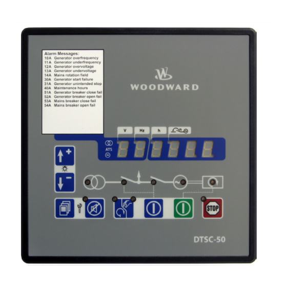
- Page 1 37441C DTSC-50 ATS Controller Manual Software Version: 1.00xx or higher Manual 37441C...
- Page 2 Provides other helpful information that does not fall under the warning or caution categories. Woodward reserves the right to update any portion of this publication at any time. Information provided by Woodward is believed to be correct and reliable. However, Woodward assumes no responsibility unless otherwise expressly undertaken.
-
Page 3: Table Of Contents
Manual • Minor corrections New device features & updates Requirements: DTSC-50 ATS control with software version 1.0004 or higher and device revision B or higher. The described changes relate to the previous software version 1.0003. New features • Modbus protocol was implemented Content 1. - Page 4 PERATION AND AVIGATION Operation and Display ........................... 28 Purpose of the Status LEDs ......................28 Operating the DTSC-50 ....................... 28 Acknowledging Alarm Messages....................28 Configuring the DTSC-50 ......................29 Display of the Operating Values ....................29 Default Operating Value Display ....................30 Cycling Through the Displayed Operating Values ...............
- Page 5 Product Service Options ........................101 Returning Equipment For Repair......................101 Packing a Control ........................102 Return Authorization Number RAN .................... 102 Replacement Parts ..........................102 How To Contact Woodward ......................... 103 Engineering Services ........................... 104 Technical Assistance ........................... 105 © Woodward Page 5/106...
- Page 6 Figure 4-1: Housing - panel cut-out ............................12 Figure 5-1: Wiring diagram – DTSC-50 ........................... 14 Figure 6-1: DTSC-50 back view - terminal arrangement ......................15 Figure 6-2: Power supply ................................16 Figure 6-3: Voltage measuring - generator 3Ph 4W ......................... 18 Figure 6-4: Voltage measuring - generator 3Ph 3W .........................
-
Page 7: Chapter 1. General Information
Manual 37441C DTSC-50 - ATS Controller Chapter 1. General Information Related Documents ≡≡≡≡≡≡≡≡≡≡≡≡≡≡≡≡≡≡≡≡≡≡≡≡≡ Type English German DTSC-50 DTSC-50 – Manual this manual 37441 Additional Manuals LeoPC1 – User Manual 37146 GR37146 PC program for configuration, parameter visualization, remote control, data logging, language upload, alarm and user management, and event recorder management. -
Page 8: Overview
Manual 37441C DTSC-50 - ATS Controller Overview ≡≡≡≡≡≡≡≡≡≡≡≡≡≡≡≡≡≡≡≡≡≡≡≡≡ Figure 1-2: Functional overview Page 8/106 © Woodward... - Page 9 Manual 37441C DTSC-50 - ATS Controller The DTSC-50 generator set controller provides the following functions: • Genset control • Engine and generator protection • Engine data measurement - including battery voltage, service hours, etc. • Generator voltage measurement Alarm display with circuit breaker trip and engine shutdown •...
-
Page 10: Dtsc-50 Overview
DTSC-50 Overview NOTE Some parameters of the DTSC-50 can only be configured using the Direct Configuration Cable DPC (P/N 5417-557) and a notebook/PC with the software LeoPC1. These parameters are indicated with an in the parameter description under Parameters starting from page 52 and can not be configured at the unit directly. -
Page 11: Chapter 3. Electrostatic Discharge Awareness
CAUTION To prevent damage to electronic components caused by improper handling, read and observe the pre- cautions in Woodward manual 82715, Guide for Handling and Protection of Electronic Controls, Print- ed Circuit Boards, and Modules. NOTE The unit is capable to withstand an electrostatic powder coating process with a voltage of up to 85 kV and a current of up to 40 µA. -
Page 12: Chapter 4. Housing
Manual 37441C DTSC-50 - ATS Controller Chapter 4. Housing Dimensions / Panel Cut-Out ≡≡≡≡≡≡≡≡≡≡≡≡≡≡≡≡≡≡≡≡≡≡≡≡≡ Figure 4-1: Housing - panel cut-out Description Dimension Tolerance Height Total 158 mm Panel cut-out 138 mm + 1.0 mm Housing dimension 136 mm Width Total... -
Page 13: Installation
Manual 37441C DTSC-50 - ATS Controller Installation ≡≡≡≡≡≡≡≡≡≡≡≡≡≡≡≡≡≡≡≡≡≡≡≡≡ For installation into a door panel, proceed as follows: Panel cut-out Cut out the panel according to the dimensions in Figure 4-1. Remove terminals Loosen the wire connection terminal screws on the back of the unit and remove the wire connection terminal strips if required (1). -
Page 14: Chapter 5. Wiring Diagrams
Common (terminals 10 to 14) Relay [R 04] Free configurable Relay [R 05] Free configurable Relay [R 06] Free configurable Subject to technical modifications. DTSC-50 Wiring Diagram | Rev. NEW Figure 5-1: Wiring diagram – DTSC-50 Page 14/106 © Woodward... -
Page 15: Chapter 6. Connections
The wire sizes in the following chapter are indicated in square millimeters. Please refer to Conversion Chart: Wire Size on page 90 to convert the sizes to AWG. Terminal Arrangement ≡≡≡≡≡≡≡≡≡≡≡≡≡≡≡≡≡≡≡≡≡≡≡≡≡ 2019 upper terminal strip configuration plug lower terminal strip 2122 3536 Figure 6-1: DTSC-50 back view - terminal arrangement © Woodward Page 15/106... -
Page 16: Power Supply
For a proper operation of the device, a minimum initial voltage of 10.5 Vdc is necessary when switching on the DTSC. After this, a continuous operating voltage between 6.5 and 32 Vdc is possible to operate the DTSC-50 safely. The control unit is capable of handling voltage drops to 0 V for a maximum of 10 ms. -
Page 17: Voltage Measuring
Manual 37441C DTSC-50 - ATS Controller Voltage Measuring ≡≡≡≡≡≡≡≡≡≡≡≡≡≡≡≡≡≡≡≡≡≡≡≡≡ The DTSC-50 allows the use of different voltage measuring methods for generator and mains voltage depending on the model. These are described in the following text. Measuring Description method Measurement is performed phase-neutral (WYE connected system). Phase voltages and neutral conductor must be connected for proper calculation. -
Page 18: Voltage Measuring: Generator
Manual 37441C DTSC-50 - ATS Controller Voltage Measuring: Generator Voltage Measuring: Generator 3Ph 4W Generator voltage 3Ph 4W Figure 6-3: Voltage measuring - generator 3Ph 4W Voltage Measuring: Generator 3Ph 3W Generator voltage 3Ph 3W Figure 6-4: Voltage measuring - generator 3Ph 3W... -
Page 19: Figure 6-6: Voltage Measuring - Generator 1Ph 2W, Phase-Neutral
In this case, phase L2 must be connected to the N terminal of the DTSC-50 and the Generator rated voltage (Parameter 11) must be configured to the phase-phase voltage. -
Page 20: Voltage Measuring: Mains
Manual 37441C DTSC-50 - ATS Controller Voltage Measuring: Mains Voltage Measuring: Mains 3Ph 4W Mains voltage 3Ph 4W Figure 6-8: Voltage measuring - mains 3Ph 4W Voltage Measuring: Mains 3Ph 3W Mains voltage 3Ph 3W Figure 6-9: Voltage measuring - mains 3Ph 3W...
Need help?
Do you have a question about the DTSC-50 and is the answer not in the manual?
Questions and answers