
Related Manuals for Woodward DPG-23-00 Series


Summary of Contents for Woodward DPG-23-00 Series
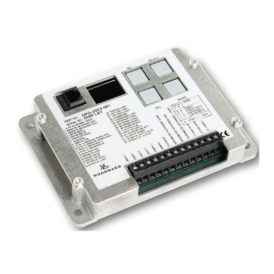
- Page 1 Released Product Manual 36527 (Revision H, 01/2024) Original Instructions DPG-23XX-00X Digital Controllers Programmable Controllers for Off-Highway Vehicle Applications Installation and Operation Manual...
- Page 2 Revisions— A bold, black line alongside the text identifies changes in this publication since the last revision. Woodward reserves the right to update any portion of this publication at any time. Information provided by Woodward is believed to be correct and reliable. However, no responsibility is assumed by Woodward unless otherwise expressly undertaken.
-
Page 3: Table Of Contents
Engineering Services ..........................54 Contacting Woodward’s Support Organization ................... 54 ........................55 EVISION ISTORY .......................... 56 ECLARATIONS The following are trademarks of Woodward, Inc.: • DPG 23XX-00X The following are trademarks of their respective companies: • Windows (Microsoft Corporation) •... - Page 4 Table 5-2. Remote Speed Pot Calibration Sequence ................. 39 Table 6-1. DPG- 2302-00X Terminal Functions..................41 Table 6-2. DPG 2345-00X Terminal Functions ................... 42 Table 6-3. Speed Operating Modes ......................47 Table 7-1. Display Codes ..........................49 Table 7-2. Troubleshooting Chart ....................... 49 Woodward...
-
Page 5: Warnings And Notices
Be prepared to make an emergency shutdown when starting the engine, turbine, or other type of prime mover, to protect against runaway or overspeed with possible personal injury, loss of life, or property damage. Start-up Woodward... - Page 6 Released Manual 36527 DPG-23XX-00X Digital Controllers On- and Off-highway Mobile Applications: Unless Woodward's control functions as the supervisory control, customer should install a system totally independent of the prime mover control system that monitors for supervisory control of engine (and takes appropriate...
-
Page 7: Electrostatic Discharge Awareness
Do not touch the components or conductors on a printed circuit board with your hands or with conductive devices. To prevent damage to electronic components caused by improper handling, read and observe the precautions in Woodward manual 82715 , Guide for Handling and Protection of Electronic Controls, Printed Circuit Boards, and Modules. - Page 8 3. The input is susceptible to RF noise such as switching transients and transmitter signals coupled into the communication cable. Cable orientation and short cable length may be used to eliminate these issues, depending on the severity of the environment. Woodward...
-
Page 9: Chapter 1. General Information
DYNA 2500 DYNA 70025 DYNA 8200 APECS 0250 DYNA 10141 DYNA 8400 APECS 0300 APECS Linkage Free Integral Type Other Models Available DPG-2100 Series – for Genset Applications DPG-2200 Series – for Genset Applications DPG-2401 Series – for EFC Valve Applications Woodward... -
Page 10: Chapter 2. Specifications
Table 2-3. Mechanical Specifications Ambient Operating Temperature -40 °F to +185 °F (-40 °C to +85 °C) Sealing Oil, water, and dust resistant via conformal coating and die cast enclosure Weight 0.75 lbs. (0.34 kg) Connection 13-terminal Euro-style connector Woodward... -
Page 11: User Interface Operation
DEC key Decrease the parameter ID number by one. Activate PARAMETER EDIT MODE on the SELECT key parameter whose number was blinking. Display the version number of the controller’s ENTER programming. INC & DEC Turn on all LED segments as a test. Simultaneously Woodward... -
Page 12: Keypad
Nonvolatile memory is where parameter values are stored so that they are remembered even when the controller is not being powered. In PARAMETER SELECT MODE, pressing the ENTER key displays the version number of the controller’s programming. Woodward... - Page 13 In PARAMETER SELECT MODE, pressing both the INC and DEC keys at the same time will cause all LED segments to be turned on. This serves as an LED test. Release the keys to resume displaying the parameter ID number. Woodward...
-
Page 14: Led Display
Example 2: The desired set speed is 10,972 Hertz. The upper two digits displayed by the controller will be [A.9] and the lower 2 digits displayed will be [72.] Table 2-7. Decimal to Hexadecimal Conversion Chart Decimal Hexadecimal Value Equivalent Woodward... -
Page 15: Chapter 3. Parameter Reference
Parameters marked with an asterisk ( ) are displayed as RPM values when the No. of Flywheel Teeth is greater than zero. These parameters can be changed with PST max by 100 (MPU input) or 10 (IGNITION input) at once when engine is running. Woodward... - Page 16 E1 Handler Select 1000 (25) 10 (2) 11000 (300) Startup Speed Startup Duty Cycle Speed Pot Action Parameters 4, 6, 7, 8, 11, 13, 14, and 31 require adjustment, while adjustments to the other parameters are optional. See Important Note above. Woodward...
-
Page 17: Parameter Functions
SPEED MIN, REMOTE SPEED MAX, SET SPEED A, IDLE SPEED, OVER SPEED LIMIT, SET SPEED A MIN, SET SPEED A MAX, IDLE SPEED MIN, IDLE SPEED MAX, STARTUP SPEED and PGAIN WINDOW parameters are displayed as RPM values instead of Hertz values. Woodward... - Page 18 If the controller’s DIG IN A and DIG IN B inputs are not used the Remote Speed Pot determines the controller’s target speed after the startup sequence is completed. Woodward...
-
Page 19: Figure 3-1. Output Response To A Step Change In Speed Error
The integral gain changes the time it takes to drive the error to zero. Note: Integral is needed to eliminate speed offsets due to proportional gain and should never be left at zero. Woodward... -
Page 20: Figure 3-2. Integral Response To Constant Error
This value along with the OVG @ Remote Speed Max value is used to select between single point gain vs. dual point gain. When OVG @ Remote Speed Max is zero, the OVG @ Remote Speed Min value is used over the full speed range of the remote speed pot. Woodward... - Page 21 8-cylinder engines. The following formula can also be used to derive a good starting point for the speed filter value for a given engine application. Round the result to the nearest integer. The maximum value allowed is 24. [(No._of_flywheel_teeth) / (No._of_engine_cylinders)] * 0.75 = speed_filter_value Woodward...
- Page 22 The unit in which the parameter value is specified is the same as for accel rate parameter (see Parameter 3.15) The formula to use for determining a precise Startup Rate is shown below. [(final_target_speed) – (crank_speed)] / (ramp_time_in_seconds) = startup_rate_value Woodward...
- Page 23 Fuel limiting is achieved by setting the maximum level of electrical current allowed to flow through the actuator during normal operation. If the value is set too low the engine will not be able to carry its rated load. Woodward...
- Page 24 Password protection is provided to guard against inadvertent parameter changes that may occur whenever the keys are pressed and a parameter modification is not intended. The password protection has three possible settings: DISABLED, LOCKED, and UNLOCKED. These settings can be modified with built-in user interface only (not Universal PST). Woodward...
- Page 25 Set Speed A Min is used to set the lowest value allowed for adjustments of Set Speed A. This parameter can be set to any value within the range bordered by 10 Hertz (2 Hertz ignition) and the current value of Set Speed A. Woodward...
- Page 26 Negative logic would produce a one, one pattern. This is shown in the table below. Table 3-2. DIG IN A and B Logic Selection DIG IN A and B Mode Select Logic Input Logic 0 = Positive logic Open contact 1 = Negative logic Open contact Woodward...
- Page 27 SPEED MIN, REMOTE SPEED MAX, SET SPEED A, SET SPEED B, OVER SPEED LIMIT, SET SPEED A MIN, SET SPEED A MAX, SET SPEED B MIN, SET SPEED B MAX and STARTUP SPEED parameters are displayed as RPM values instead of Hertz values. Woodward...
- Page 28 Table 3-3. Controller Interpretation of Remote Set Speed Signal Input Pedal Action Remote Set Speed Direction Setting Input Voltage 0 = Forward Acting Increase 1 = Reverse Acting Decrease The DPG-23XX defaults to forward acting mode. This parameter is automatically set during Remote Speed Potentiometer Calibration Procedure. Woodward...
-
Page 29: Chapter 4. Universal Pst
Only trained personnel should have access to these tools. Acquiring Universal PST The Universal PST software can be downloaded from the Woodward website. If you also require connection hardware you may purchase a calibration kit from Woodward. Both download and kit request instructions are described below. -
Page 30: Installing Universal Pst
Download the newest Universal PST version from the search results. You will be asked to log in to Woodward’s website if you haven’t already done so. After login, you will see the File Download dialog box shown below, or one similar. Click the [Save] button and choose a folder to save the download to. -
Page 31: Figure 4-1. Wiring Diagram
No connection Figure 4-1. Wiring Diagram Remote access via the COMM port is intended for connection only while programming, tuning and troubleshooting the control/engine. It is a service port and not intended for permanent connection of a PC and/or cable. Woodward... -
Page 32: Universal Pst User Interface Overview
• Press the <Write All> button to transmit setup values to the controller. • Press the <View Status> button to display read only parameters in the Status View panel. • Press the <View Chart> button to set the display mode to Chart View. • Select items from the menu. Woodward... -
Page 33: Figure 4-3. Chart View Screen
• Press the <View Table> button to set the display mode back to Table View. • Select items from the menu. NOTE: Pressing a button means positioning the mouse pointer over the button and clicking the left mouse button. Woodward... -
Page 34: Universal Pst Menu Items
Use the Help Menu to access: • Help on the Universal PST for DPG • Help on the DPG-23XX-00X that is currently in communication with the PC • Information about the Universal PST for DPG application Figure 4-7. Universal PST Help Menu Woodward... -
Page 35: Parameter Setup
The <Write All> button is very useful when reusing saved setup data to configure a new system with the same data as a previous one. Simply load an existing set of previously saved parameter values into the Parameter Setup table using “Open a setup data file” from the File menu then press the <Write All> button. Woodward... -
Page 36: Figure 4-9. Status View Panel
Value column. The selected cell will be highlighted and the value can now be modified. When done modifying the value, press the computer keyboard’s <Enter> key to transmit the new value to the controller. Figure 4-10. Tuning View Panel Woodward... -
Page 37: Figure 4-11. Chart Recorder Panel
IMPORTANT: Do not open data files in another program that are currently being used by Universal PST. Also be sure to close any open data files needed by Universal PST before starting it. Figure 4-12. Engine Speed Data Collection Woodward... - Page 38 Use the <View Table> button to return to the Table View display mode. Be sure to open a new Data File before returning to Table View if the data already collected needs to be saved. The active data file is automatically reset each time the Chart View display mode becomes active. Woodward...
-
Page 39: Chapter 5. Calibration
Add some integral to eliminate any steady-state error in the engine’s speed and help decrease error recovery time. The overall gain can be increased to improve response time while keeping the ratios of the PID terms relative to each other constant. Woodward... -
Page 40: Figure 5-1. Pid Response To Errors
To use a Remote Speed Pot, a calibration sequence must be done first (see Table 5-2). DPG-23XX-001 Models Calibration sequence can be done only using the controller’s built-in user interface. DPG-23XX-002 Models Calibration sequence can be done using either the controller’s built-in user interface or Universal PST. Woodward... - Page 41 12 seconds for the target speed to ramp up 3000 Hertz (SET SPEED A minus STARTUP SPEED) and reach point C. The startup sequence ends at point C assuming the engine speed has been tracking the target speed and has reached SET SPEED A. Woodward...
-
Page 42: Figure 5-2. Startup Sequence
Released Manual 36527 DPG-23XX-00X Digital Controllers Figure 5-2. Startup Sequence Woodward... -
Page 43: Chapter 6. Installation
Remote Speed Pot +5 V Supply voltage for the remote speed pot CW DIG IN A Mode select input A DIG IN B Mode select input B +5 Vdc Supply voltage for DIG IN A & DIG IN B inputs Woodward... -
Page 44: Wiring Diagrams
Supply voltage for DIG IN A & DIG IN B inputs Wiring Diagrams Cabling for DPG 23XX-00X controllers is limited to less than 30m (98.4’). Power cabling is limited to less than 10m (32.8’) in total length. The wiring diagrams below shows specific cable types required. Woodward... -
Page 45: Figure 6-1. Wiring Diagram For Dpg- 2302-00X Controller
To prevent damage to the controller, make sure that it is wired in accordance with the wiring instructions and diagrams in this manual. • Do not tin the leads before placing them into the terminals. • Ensure the terminals are tightened properly to secure wires. Woodward... -
Page 46: Figure 6-2. Wiring Diagram For Dpg-2345-00X Controller
To prevent damage to the controller, make sure that it is wired in accordance with the wiring instructions and diagrams in this manual. • Do not tin the leads before placing them into the terminals. • Ensure the terminals are tightened properly to secure wires. Woodward... -
Page 47: Centralized Suppression
• Unsuppressed, switched inductive loads are in parallel or series with the control power. • The input power is derived from a distribution system or it is more than 32.8’ (10m) from the control to the main power source Woodward... -
Page 48: Figure 6-3. Centralized Suppression Implemented At The System Level
4. Suppression kits available from Woodward are intended to suppress the majority of the likely pulses. However, they will not protect against all system level implementations outside the intended usage of the control. -
Page 49: Mode Selection
REMOTE SPEED INPUT changes. While in SET SPEED B mode, the controller will command the engine to run at the SET SPEED B set speed. The controller will not respond to any REMOTE SPEED INPUT changes. Figure 6-4. Pedal Mode Woodward... -
Page 50: Figure 6-5. Pedal Hold Mode
Released Manual 36527 DPG-23XX-00X Digital Controllers Figure 6-5. Pedal Hold Mode Figure 6-6. Set Speed A Mode Figure 6-7. Set Speed B Mode Woodward... -
Page 51: Chapter 7. Diagnostics & Troubleshooting
If not greater than 5%, then restore all parameter values to factory default settings and crank the engine again. Engine Overspeeds at Increase the Proportional value. Startup Increase the appropriate OVG (overall gain) value. Use the Startup Limit. Decrease the Startup Ramp Rate. Woodward... - Page 52 Sluggish Response to Improve PID tuning. Load Changes Speed filter setting is too high. Engine Instability With No Improve PID tuning. Load Speed filter setting is too low. Fuel is restricted. Check actuator linkage. Battery voltage is too low. Woodward...
- Page 53 Difference between No Load and Full Load calibration values is too small. Should be > 100 for best performance. Modify or adjust actuator linkage to increase range of actuator loading. If finer droop control is required, then use a DPG-2223-00X controller. Woodward...
-
Page 54: Chapter 8. Product Support And Service Options
• An Authorized Independent Service Facility (AISF) provides authorized service that includes repairs, repair parts, and warranty service on Woodward's behalf. Service (not new unit sales) is an AISF's primary mission. A current list of Woodward Business Partners is available at www.woodward.com/local-partner... -
Page 55: Returning Equipment For Repair
All repair work carries the standard Woodward service warranty (Woodward Product and Service Warranty 5-09-0690) on replaced parts and labor. -
Page 56: Replacement Parts
• The unit serial number, which is also on the nameplate Engineering Services Woodward offers various Engineering Services for our products. For these services, you can contact us by telephone, by email, or through the Woodward website. • Technical Support •... -
Page 57: Revision History
Changes in Revision H— • Removed EPG 512 and EPG 1724 from Table 1-1 • Added Lockout/Tagout and IOLOCK warnings (pages 3 & 4) • Updated Electrostatic Discharge Awareness section (page 5) • Updated Product Support section (Chapter 8) Woodward... -
Page 58: Declarations
Released Manual 36527 DPG-23XX-00X Digital Controllers Declarations Woodward... - Page 59 Released Manual 36527 DPG-23XX-00X Digital Controllers THIS PAGE INTENTIONALLY LEFT BLANK Woodward...
- Page 60 Email and Website—www.woodward.com Woodward has company-owned plants, subsidiaries, and branches, as well as authorized distributors and other authorized service and sales facilities throughout the world. Complete address / phone / fax / email information for all locations is available on our website.
Need help?
Do you have a question about the DPG-23-00 Series and is the answer not in the manual?
Questions and answers