Table of Contents
Advertisement
Quick Links
Advertisement
Table of Contents

Related Manuals for Avery Weigh-Tronix WI-105


Summary of Contents for Avery Weigh-Tronix WI-105
-
Page 3: Table Of Contents
Table of Contents ......................3 Specifications ........................ 4 Safety ........................5 Introduction ........................6 The Manuals ......................6 The WI-105 ......................6 Installation ........................7 Overall Dimensions ....................7 Panel Cutout ......................7 Fastening Clips ....................... 7 Wiring, Links, and Fuse Replacement ................8 Display and Controls ..................... -
Page 4: Specifications
Specifications Power requirements: Standard: 95-265 AC/DC, 8VA typical Optional: 12 VDC, 8VA typical Excitation: 10 VDC supports up to four 350-ohm weight sensors Operational keys: ZERO, TARE, PRINT, TRIPS (cutoff) Display: 5½ digits (199999) Seven segment bright red LED 0.56" high Display update rate: Five times per second Display resolution: up to 50,000 divisions Capacity selections:... -
Page 5: Safety
Safety WARNING This equipment is supplied by voltage which can cause an electric shock injury. Before removing the instrument from it’s housing, switch the instrument off, isolate it from the power supply and make sure that it cannot be connected inadvertently by other persons. This instrument may only be used when housed within another enclo- sure, e.g. -
Page 6: Introduction
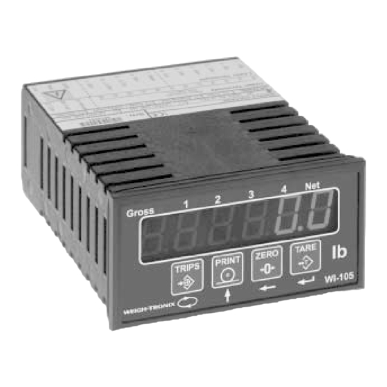
The WI-105 latest technology to ensure fast and accurate weight readings. The WI-105 has a 5 1/2 digit (-199999 to 199999 counts) bright red LED display. It is designed for mV inputs from load cells, strain gauges & strain pressure transmitters. This compact panel mount instrument has an industry standard DIN 48 x 96 housing. -
Page 7: Installation
Installation Overall Dimensions O-ring sealing gasket supplied as standard. Panel Cutout Fastening Clips The fastening clips supplied may be fitted on the side or the top/bottom of the instrument. Ensure that the To gain access to the PCB, switch clip and screw is mounted as power off and remove terminals shown here. -
Page 8: Wiring, Links, And Fuse Replacement
Wiring, Links, and Fuse Replacement Be sure all cabling has adequate strain relief. -
Page 9: Display And Controls
Display and Controls Keypad During Configuration Mode Keypad During Normal DisplayMode The instrument may be reinitialized at any time, with factory default Cold Start / Restoring settings restored. To achieve this, switch the instrument off. Press and Factory Settings keep pressing the right two most keys while powering up the instrument. Release the keys when COLD appears on the display. -
Page 10: Setup And Calibration
Setup and Calibration This instrument offers an easy and straightforward way to precalibrate and field calibrate the load cell system. Follow the steps below: There is only one user selectable link, the excitation link. The default Step 1: Selecting setting is for 10V excitation, which is suitable for most applications. Note Excitation Voltage that the precalibration feature only works with the 10V excitation. -
Page 11: Step 4: Field Calibration Of Deadweight (Back-Balance)
Example 2 For a 3 x 1000 lb capacity load cell system with 2mV/V each. Program the instrument as follows: - Go to the Ser and Pre.C menu. - After Volt appears, set 2.00 for mV/V sensitivity. - Set decimal point to 0000 (no decimal places). - Set SF.1 to 0. -
Page 12: Step 7: Protecting Service Parameters
DO NOT change these parameters. It is suggested that these parameters be noted for future use, especially if the instrument is replaced. These parameters can be reentered into the new instrument, with the result that reasonable accuracies can still be obtained without redoing a field calibra- tion. -
Page 13: Configuration Menu
Configuration Menu Figure 1 Configuration Menu... -
Page 14: Service Menu
Below are the displays you will see while navigating the configuration menu shown in Figure 1. Following that is the menu itself. Your unit may Passcode = press the four not have all options installed so you will not see all the items listed below front panel keys from right to or in the menu itself. - Page 15 Single point span calibration of load cell. Set to Menu test weight value and press enter. During span calibration using test weights, display flashes. Menu exits automatically. Communications menu (RS-232/RS-485). Menu Unit address (default 0) Available baud rates Protocol selection and serial interface function. Off = Not used Out = ASCIIBus output In = ASCIIbus input.
-
Page 16: Display Messages For Options
Alarm 1-4 setpoint values. Alarm configuration menu (1st alarm only shown). Menu 1st Alarm setpoint select HIGH/LOW alarm 1st Alarm setpoint normally OPEN/CLOSED contact. 1st alarm setpoint hysteresis. 1st alarm setpoint delay. Alarm latching. Off = not latching, On = alarm latches. -
Page 17: Option Menu For Tare And Peak/Valley Hold
Option menu for Tare feature and Peak/Valley Menu Hold. Tare feature select (auto-zero / auto-tare). Turn the Tare feature on or off This does not disable the remote tare. Peak / valley hold feature (min. / max. hold). Turn the peak / valley hold feature on or off. Peak / valley hold selector. -
Page 18: Options
Options RS-485 Communica- tions Option RS-232 communications is standard on the WI-105. However, if RS-485 is preferred, then the following steps must be taken. - Switch power off and isolate. - Carefully remove circuit board from it’s housing (see installation sec- tion). -
Page 19: Analog Output Option
The upper board and terminals are clearly numbered 13-28 to differentiate them from the lower terminals. The analog output board simply connects to the WI-105 motherboard via the option connector. To fit analog output board, use the following procedure: - Switch power off and isolate. -
Page 20: Four Trip Relays Option
The upper board and terminals are clearly numbered 13-28 to differentiate them from the lower terminals. The relay option board simply connects to the WI-105 motherboard via the option connector. To fit this option board, use the following procedure: - Switch power off and isolate - Carefully remove circuit board from it’s housing (see installation... - Page 21 Connection diagram for electromechanical relay card: Connection diagram for solid-state relay card: Both analogue output option and trips option is available on one instrument. Refer to the appropriate sections of the manual for wiring information.
-
Page 22: Appendix A: Rs-232 Connection To Computer
ASCll input (WI-105 acting as a remote indicator) function is enabled in the “Conn” (connection) sub-menu by selecting “ASCI” to “In”. In this mode, the WI-105 will act as a serial input indicator and will show the incoming data / weight on the display. Note that all load cell menu functions are ignored. -
Page 23: Communication Settings
Line Settings : 7 Data Bits, Odd Parity, 1 Stop Bit. Communication Baud Rate: Selectable 2400, 4800, 9600, 19200. Settings Data ASCll characters: 0, 1, 2, 3, 4, 5, 6, 7, 8, 9 or _ (space) Other characters: G, N, .(dp), +, -, CR, LF Note that the decimal point Output string formats are (fixed length protocol): position in the protocol will... - Page 26 Weigh-Tronix 1000 Armstrong Dr. Fairmont, MN 56031 USA Telephone: 507-238-4461 Facsimile: 507-238-4195 e-mail: industrial@weigh-tronix.com www.wtxweb.com Weigh-Tronix Canada, ULC 217 Brunswick Blvd. Pointe Claire, QC H9R 4R7 Canada Telephone: 514-695-0380 Facsimile: 514-695-6820 Weighing Products & Systems Weigh Bar is a registered trademark of Weigh-Tronix Inc. ®...
Need help?
Do you have a question about the WI-105 and is the answer not in the manual?
Questions and answers