
Subscribe to Our Youtube Channel
Related Manuals for SIGLENT SHS815


Summary of Contents for SIGLENT SHS815
- Page 1 User Manual SHS800 Series Handheld Digital Oscilloscope UM03008-E05A SIGLENT TECHNOLOGIES CO,.LTD...
- Page 3 1. Copyright © SIGLENT TECHNOLOGIES CO., LTD. 2. Information in this manual takes place of all data published before. 3. SIGLENT company reserves the rights to change specifications and price. 4. Contents in this manual are not allowed to be copied, extracted and translated without permission by the company.
- Page 4 Safety Information Carefully read the following safety information before using the SHS800. Specific warning and caution statements, where they apply, appear throughout the manual. A “Warning” identifies conditions and actions that pose hazard(s) to the user. A “Caution” identifies conditions and actions that the user should notice. The following international symbols are used on the SHS800 and in this manual: Hazardous Protective...
- Page 5 Do not insert metal objects into connectors. Use of the SHS800 in a manner not specified may impair the protection provided by the equipment. Before use, inspect the test leads for mechanical damage and replace damaged test leads! Whenever it is likely that the safety has been impaired, the SHS800 must be turned off and disconnected from the line power.
-
Page 6: Safety Operation Of Battery
Safety Operation of Battery SHS800 series handheld digital oscilloscope can be used to test float signal when power supplied by battery. When using the double channels to test float signal, the two channels should be connected to the same earth ground, because the earth ground of the two channels is connected Warning: Do not connect the ground spring to voltages higher than 42 V peak or 30Vrms from... -
Page 7: Introduction Of Shs800 Series
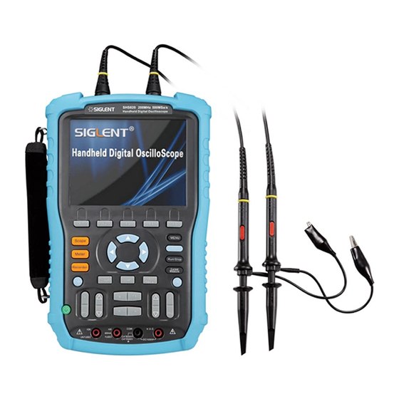
Introduction of SHS800 Series This manual mainly introduces SHS800 series Handheld Digital Oscilloscope. The SHS800 series is a high performance handheld oscilloscope with great range of dynamic input scope. It has small volume which convenient to carry, compact interface and etc. It satisfies the most needs of outside measurement and improves working efficiency greatly. -
Page 8: Accessories Of Shs800
Accessories of SHS800 A user manual A product guaranty card A certification Two 1:1/10:1 probes An USB cable A adapter Meter pens for multimeter A Probes calibrated device A CD (including EasyScope3.0 computer software system) ... -
Page 9: Table Of Contents
Table of Contents Safety Information ........................II Safety Operation of Battery ....................IV Introduction of SHS800 Series ....................V Function Characteristics ......................V Accessories of SHS800 ......................VI Chapter 1 Accidence ........................1 Accidence of the Front Panel and User Interface ..............1 Function Check ......................... - Page 10 Chapter 6 Service and Support ....................64 Maintain Summary........................64 Contact SIGLENT ........................64 Appendix A: Default Setup ..................... 65 Appendix B: Battery Installation .................... 67 Appendix C: Daily Maintaining and Cleaning ..............6 8 VIII SHS800 Series...
-
Page 11: Chapter 1 Accidence
Chapter 1 Accidence About this Chapter This chapter mainly covers the following contents: Get a primary understanding of the front panel and user interface A brief function check Probe compensation Accidence of the Front Panel and User Interface You’d better get an understanding of the front panel before you operate the SHS800 series Handheld Digital Oscilloscope. - Page 12 Description 1. power on/off key 10. menu on/off key 2. CH1 vertical range and position key 11. arrow keys 3. CH1 on /off key 12. Auto, Run/Stop, Cursor function 4. Scope, Meter, Recorder function keys menu 13. CH2 on/off key 5.
- Page 13 Figure 1-3 User Interface Description 1. Trigger state Armed: The scope is acquiring data of pre-trigger ,please ignore all triggers under this state. Ready: The scope has sampled all pre-triggers data and is ready to accept trigger. Trig’d: The scope has found a trigger and is sampling data after trigger. Stop: The scope stops sampling data.
-
Page 14: Function Check
Function Check and Probe Compensation Function Check Let’s make a quick function check to make sure whether the SHS800 works normally. Please do the following steps: Power the SHS800. The SHS800 performs all the self check items and makes sure that it passes the self check. -
Page 15: Chapter 2 Using The Scope
Chapter 2 Using the Scope About this Chapter This chapter provides a step-by-step introduction to the scope functions of SHS800 series. The introduction gives basic examples to show how to use the menus and perform basic operations without d covering all of the capabilities of the scope functions。... -
Page 16: Automatic Settings
Automatic Settings When measuring unknown signals and having no idea about its voltage, range, frequency, trigger and other information, you can use the automatic setting function. Automatic Setting Application Example Operating steps: 1. Input a signal to CH1 or CH2 and then press 【Auto】. 2. - Page 17 Table 2-2 CH1/CH2 function Menu 1 Option Setting Instruction DC passes both AC and DC components of the input signals. AC blocks the DC component of the Coupling input signals and attenuates signals below 10 Hz. GND disconnects the input signal. Limit the bandwidth above 20M to reduce display noise;...
- Page 18 Table 2-4 Digital Filter Function Menu Option Setting Introduction Turn on the digital filter. Digital Filter Turn off the digital filter. Setup as LPF (Low Pass Filter). Setup as HPF (High Pass Filter). Type Setup as BPF (Band Pass Filter). Setup as BRF (Band Reject Filter).
-
Page 19: Scope's Function Menu
Figure 2-6 After Turn On the Digital Filter Scope’s Function Menu The button 【Scope】 includes the following functions: Figure 2-7 Scope Function Menu Acquire Signals System Press 【Scope】 and choose Acquire to enter acquiring system. See Figure 2-8. Figure 2-8 Acquire Signals system function menu SHS800 Series 9... - Page 20 Table 2-5 Acquiring Signals System Function Menu Option Setting Introduction Sampling Sample and display most waveforms accurately. Acquisition Peak Detect Detect burr and reduce fake wave phenomena. Average Reduce random and irrelative noise. (4, 16, 32, Averages Select the times of averages. 64,128,256〕...
-
Page 21: Display System
Figure 2-10 X Interpolation Display System Press 【Scope】 and choose Display to enter display system. See Figure 2-6. Figure 2-11 Display Menu 1 Table 2-6 Display System Function Menu Option Setting Introduction Vectors fill the space between adjacent Vectors Type sample points in the display. - Page 22 Table 2-7 Display system function menu 2: Option Setting Introduction YT format displays the vertical voltage in relation to time (horizontal scale). Format XY format displays a dot each time a sample is acquired on channel 1 and channel 2. Normal Set to normal mode.
-
Page 23: Math Waveform
Math Waveform Press 【Scope】 and choose Math to enter the math waveform function menu. Figure 2-14 MATH Menu Table 2-8 Math Menu Function Option Setting Instruction + CH1+CH2 - CH1-CH2、CH2-CH1 Operation CH1*CH2 CH1/CH2、CH2/CH1 Fast Fourier Transform. Invert the waveform. Invert Turn off the invert function Page1/2 Next Page... - Page 24 Figure 2-16 Result of Two Waveforms Add About FFT operation Using FFT math operation can translate time field signal to frequency field signal. Figure 2-17 FFT Function Menu 1 Figure 2-18 FFT Function Menu 2 Table 2-10 FFT Window Function Window Characteristic Advantage content...
-
Page 25: Horizontal System
FFT Zoom: zoom in FFT waveform vertically by 1X, 2X, 5X and 10X. Scale: choose dBVrms or Vrms as a measure unit. Display: Spilt or Full Screen FFT waveform display mode. FFT Waveform Operation Application Example Operation steps: 1. Input a signal to CH1 and press 【Auto】. 2. - Page 26 Delay Scan Application Example Operation steps: 1. Input a waveform to CH1 or CH2. 2. Adjust time base to display the best waveform. 3. Press 【Scope】 and then choose Horizontal to enter horizontal system. 4. Press 【F1】 to turn on delay scan. 5.
-
Page 27: Reference Waveform
Figure 2-23 Long Memory Reference waveform Press 【Scope】 and choose Ref to enter the reference waveform function menu. Figure 2-24 Reference waveform Menu Table 2-11 REF Waveform Function Menu Instruction Function Setting Choose the waveform to be saved. Signal CH1/CH2 Choose to save or recall the reference position of Ref A/Ref B the waveform.. -
Page 28: Cursor And Measure System
Figure 2-25 Reference Waveform Cursor and Measure System Cursor measure Press 【Cursor/Measure】 once to enter the cursor measure system. There are three modes of measure: manual, track, automatic. Manual mode: horizontal or vertical cursors appear in couple and we use them to measure voltage or time parameters. - Page 29 Track mode: In this mode, the screen displays two cross cursors. The cross cursor sets the position on the waveform automatically. You could adjust cursor’s horizontal position on the waveform by turning the arrow kyes ” . The oscilloscope displays the values on the top of the right screen.
-
Page 30: Parameter Measure
Automatic Measure Application Example Operation steps: 1. Press 【Cursor/Measure】 once to enter cursor system. 2. Press 【F1】 to choose Auto mode. 3. Press 【Cursor/Measure】 again and choose parameter types to be measured. Figure 2-29 Auto Measure Parameter Measure Press 【 Cursor/Measure 】 twice and any key of F1 ~ F5 to enter parameter measurement system.. - Page 31 Table 2-15 Voltage Measure Function Option Setting Instruction Select input signal source for Source CH1,CH2 voltage measure. Press F2 or use the arrow keys to Vpp, Vmax, Vmin, Vamp, Vtop, Type Vbase, Vavg, Mean, Vrms, FOV, select voltage measure FPRE, ROV, RPRE , parameter.
- Page 32 Table 2-17 Delay Measure Function Option Setting Instruction Select input signal source for delay Source CH1, CH2 measure. Press the “Type” button or use Phase、 FRR、FRF、FFR、FFF、 Type arrow keys select delay LRR、LRF、LFR、LFF measure parameter. Display the corresponding icon 、 、 measure value your...
- Page 33 The arithmetic mean over the entire waveform. Mean Virtual value: the true Root Mean Square voltage of the Crms first cycle in the waveform. The true Root Mean Square voltage over the entire Vrms waveform. Defined as (Vmax-Vhig)/Vamp after the waveform ROVShoot rising.
- Page 34 Parameter Measure Supplication Example Operation steps: 1. Press 【Cursor/Measure】 twice and any key of F1~F5 to enter parameter measurement system. 2. Choose any key out of F1~F5 to choose measure type. For example: Voltage. 3. Press 【F2】 to choose measure parameter. For example: Vpp. 4.
-
Page 35: Trigger System
Trigger System There are 5 kinds of trigger function: edge, pulse, video, slope, alternative. Press 【Trigger】 to enter the trigger system. Edge Trigger Figure 2-37 Edge Trigger Function Menu Table 2-20 Edge Trigger Function Menu Option Setting Instruction Trigger on the rising or falling edge of the input Type Edge signal. - Page 36 Table 2-21 Trigger Setting Menu Option Setting Instruction Passes all components of the signal Blocks DC components and attenuates signals below 170Hz. Coupling Attenuates the high-frequency components HF Reject above 140kHz. Blocks the DC component and attenuates the LF Reject low-frequency components below 7 kHz.
- Page 37 Table 2-22 Pulse Trigger Function Menu 1 Option Setting Instruction Select the pulse to trigger the Type Pulse pulse match trigger condition. Source CH1、CH2 Select input signal source. (Positive pulse width less than pulse width set) (Positive pulse width larger than pulse width setting) (Positive pulse width equal Compare the trigger conditions to pulse width setting)
- Page 38 Pulse Trigger Application Example Operations steps: 1. Input a pulse signal. 2. Press 【Trigger】 to enter trigger menu. 3. Press 【F1】 to choose pulse trigger. 4. Press 【F3】 to set pulse trigger conditions. 5. Press 【F4】 and use arrow keys to set pulse width. 6.
- Page 39 Table 2-24 Pulse Trigger Function Menu 2 Option Setting Instruction When you select the video type, put the couple set Type Video to the AC, then you could trigger the NTSC, PAL and SECAM video signal. Source CH1、CH2 Select the input source to be the trigger signal. Normal triggers on the negative edge of the sync (Normal) pulse.
- Page 40 Video Trigger Application Example Operation steps: 1. Input a video signal. 2. Press【Trigger】 to enter trigger menu. 3. Press【F1】 to choose Video. 4. Press【F5】 to enter the second page of video trigger menu. 5. Press【F2】 to set the video standard PAL/SECAM or NTSC meeting with the input signal.
- Page 41 Table 2-26 Slope Trigger Function Menu 1 Option Setting Instruction Trigger on positive slope of negative slope Type Slope according to setup time of the oscilloscope. Source CH1、CH2 Select trigger source. Condition Select trigger conditions. Use the arrow keys to set slope time. Time Time 〈Set time〉...
- Page 42 display a waveform until after the first trigger. When you want the oscilloscope to acquire Single a single waveform, press the “SINGLE ” button. Set up Enter the “Trigger setup menu”. Next Page Page 2/2 Return to the first page of slope trigger. Alternative trigger The trigger signal comes from two vertical channels when you use alternative trigger.
-
Page 43: Save And Recall System
Save and Recall System SHS800 can save 2 groups of reference waveforms, 20 groups of setups and 10 groups of waveforms in its internal memory. There is an USB Host interface in the front panel of the SHS800 and you can save setup data, waveform data, waveform interface image, CSV file to an USB flash drive. - Page 44 Saving waveform Saving waveform to device Figure 2-51 Saving Waveform to Device Menu Table 2-31 Saving Waveform to Device Function Menu Option Setup Introduction Menu for the Storage/Recall waveforms in the Type Waveforms scope. Save To Device Save waveforms to the SHS800’s internal memory.. No.1 to waveform Choose the position number to save/recall setups.
- Page 45 Table 2-33 Saving Picture Function Menu Option Setting Introduction Menu for the Storage/Recall waveform interface Type Picture image. Choose Print Picture option press Print Picture Save/Recall for 4 seconds to print the picture while the SHS800 connects to the printer. Print Key Choose Save Picture option and press...
- Page 46 4. Press 【F4】 (Save) to enter save/recall interface. 5. Press 【F1】 (Modify) to choose File. 6. Press 【F2】 (New File) and input the mane of the file according to the prompts to create a new file. Then press Confirm. Figure 2-55 Input the Name of the File 7.
-
Page 47: Utility System
Utility System Press 【User】 to enter utility system menu. See figure 2-57. Figure 2-57 Utility System Menu 1 Table 2-36 Utility System Function Menu 1 Option Setting Introduction System Displays the main information Status of the SHS800. Open the key-press voice. Sound Close the key-press voice. - Page 48 Figure 2-58 Utility System Menu 2 Figure 2-59 Utility System Print Setup Figure 2-60 Utility System Menu 3 Table 2-38 Utility System Function Menu 3 Option Setting Introduction Update You can update the SHS800 by using USB flash Firmware driver (About two minutes). Record Press this button to enter the waveform record menu.
- Page 49 Self Calibration Self Calibration is operated to calibrate the relative data of SHS800 to decrease the mistake during the measure. If the operating temperature changes by or more than 5° C or the instrument runs more than thirty minutes, you should do the self calibration. When you do the self calibration, you should cut off all the probes and leads.
- Page 50 Choose Print Picture option and press Save/Recall for 4 seconds to print the Print Picture picture while the SHS800 connects to the printer. Print Key Choose Save Picture option and press Save/Recall for 4 seconds to save the Save Picture picture while you insert an USB flash driver to the SHS800.
- Page 51 Table 2-42 Waveform Record Menu Option Setting Instruction Record Set recorder function menu. Mode Replay Set replay function menu. Turn off waveform record menu. Source CH1、CH2 Choose recorder source. Interval Set interval of recorder waveform End Frame Set the max value of recorder frame. (record)...
- Page 52 Waveform Record Application Example Operation steps: 1. Input a waveform to be recorded. 2. Press 【User】 to enter utility system. 3. Press 【F5 】to enter the third page of the menu and enter waveform recording menu. 4. Press 【F1】 to choose Record mode. 5.
-
Page 53: Chapter 3 Using The Multimeter
Chapter 3 Using the Multimeter About this Chapter This chapter provides a step-by-step introduction to the multimeter functions of SHS800 series Handheld Digital Oscilloscope. The introduction gives basic examples to show how to use the menus and perform basic operations. The digital multimeter provides the following functions: making DC voltage, AC voltage, resistance, diode, continuity, capacitance, DC current, and AC current measurements. -
Page 54: Making Dc And Ac Voltage Measurement
Making DC and AC Voltage Measurement Table 3-1 DC and AC Function Menu Option Setting Instruction Save the current input value as a reference and record again. Real value equals relative value plus Relative Value measurement value Real value equals measurement value Choose best measurement... -
Page 55: Making Resistance Measurement
Operation Steps: 1. Press 【Meter】 to enter multimeter mode, press 【F1】 to choose DCV, ACV measurement. 2. Insert the red probe to the V.Ω.C banana jack input and the black probe to the COM. Connect the other end of probes to the power or load to be measured. 3. -
Page 56: Making Diode Measurement
Making Diode Measurement Figure 3-5 Diode Measurement Operation steps: 1. Press 【Meter】 to enter multimeter mode, press 【F1】 to choose Diode measurement. 2. Insert the red probe to the V.Ω.C banana jack input and the black probe to the COM. Connect the other end of probes to the diode to be measured. 3. -
Page 57: Making Capacitance Measurement
Operation steps: 1. Press 【Meter】 to enter multimeter mode, press 【F1】 to choose Continuity measurement. 2. Insert the red probe to the V.Ω.C banana jack input and the black probe to the COM. Connect the other end of probes to the object to be measured. 3. -
Page 58: Making Dc And Ac Current Measurement
Making DC and AC Current Measurement Figure 3-8 DC Current “mA” Measurement Figure 3-9 DC Current “A” Measurement Figure 3-10 AC Current “mA” Measurement 48 SHS800 Series... - Page 59 Figure 3-11 AC Current “A” Measurement Operation steps: 1. Press 【Meter】 to enter multimeter mode, press 【F1】 to choose DCI/ACI measure. 2. Insert the red probe to the A or mA jack input and the black probe to the COM. Connect the other end of probes to the power or load to be measured. 3.
-
Page 60: Chapter 4 Using The Recorder Functions
Chapter 4 Using the Recorder Functions About this Chapter This chapter provides a step-by-step introduction to the recorder functions of SHS800 series Handheld Digital Oscilloscope. The introduction gives basic examples to show how to use the menus and perform basic operations. The recorder mainly includes the following functions: Trend Plot: Trend plot is to save the measurements in the memory and then plot a graph of Scope or Meter measurements as a function of time. -
Page 61: Oscilloscope Trend Plot
Oscilloscope Trend Plot Figure 4-1 Scope trend plot user interface 1. current recorded time 2. the percentage of recorded date take in the whole memory 3. Value of the latest recorded data point A 4. Value of the latest recorded data point B 5. - Page 62 Figure 4-3 Scope Trend plot Function Menu 2 Table 4-2 Scope Trend plot Function Menu 2 Option Setting Instruction Normal Display the data up to the minute. Display Mode View all Display all date in a compressing proportion Record data automatically Manual Record data manually.
- Page 63 Figure 4-5 Trend Plot record Curve Display recorded data 6. Press 【F5】 to enter the second page of trend plot menu. 7. Press 【F1】 to choose data display mode. Normal: the screen displays the data up to the minute. View All: the screen displays all data in the memory. 8.
-
Page 64: Waveform Recorder
Waveform Recorder Press 【Recorder】 to enter recorder main menu under scan time base, then press 【F2】 to choose Scope recorder. Figure 4-7 Waveform Recorder Menu Table 4-3 Waveform Recorder Function Menu Option Instruction Record Record waveform without gap. Replay Replay the recorded waveform. Option Setup the parameters of waveform recorder. - Page 65 Table 4-5 Waveform Recorder Replaying Mode Function Menu Option Instruction Pause or contnue playing waveform automatically, you can Stop/Continue change the time base to observe the waveform in the memory. Restart Replay the waveform Previous Back the waveform and then play. Next Speed the playing of the waveform.
- Page 66 8. Press 【F1】 to start recording data. The waveform will not move right and the recorded data saved to memory. The recorded time will be different according to the time base. You can pause or stop at any time. Figure 4-11Waveform Recorder Interface Waveform replay 9.
-
Page 67: Multimeter Trend Plot
Multimeter Trend Plot Figure 4-12 Multimeter Trend Plot User Interface 1. current recorded time 2. the percentage of the current data take in the whole memory 3. the parameter value of the recorded data up to the minute 4. DC/AC 5. - Page 68 Table 4-6 Multimeter Trend Plot Function Menu 1 function setting Instruction Quilt the current data and start to record Restart afresh. Sa Rate 10Sa…0.005Sa Set sampling rate Display normal Display the recorded data up to the minute. mode All view Display all dots.
- Page 69 Figure 4-15 Multimeter Trend Plot Recording Curve 3. Press 【F4】 to stop or run recording data. 4. At the second page of the menu you can choose manual or auto mode to record the data. Display the record data 5. Press 【F3】 to choose data display mode. Normal mode: the screen displays the data up to the minute.
-
Page 70: Chapter 5 Prompting And Troubleshooting
Chapter 5 Prompting and Troubleshooting About this Chapter This chapter gives a detailed instruction of every system prompting appears on the screen as well as some basic troubleshooting. System Prompting Messages Instruction Trig level at limit! : Mention you that the trigger level is at a limit when you turn the Trig level knob. - Page 71 internal of the oscilloscope or USB flash successful. Ready Data Success! : Read setup data or waveform data from the internal of the oscilloscope or USB flash successful. Please set USB Device to printer! : Press the “S/div” knob will appear this information on the screen when the “Print Key”...
-
Page 72: Troubleshooting
Troubleshooting 1. After the SHS800 is powered on,if the screen remains dark ,please do as following steps: Check the power cable’s connection. Ensure the power switch is turned on. After the inspections above,restart the Handheld Digital Oscilloscope. If the Handheld Digital Oscilloscope is still not used after the checking, please connect with MY company 2. - Page 73 If you can’t use the SHS800 normally all the same, please contact with SIGLENT servicing center, we will provide service for you. 8. The other kind of trouble, please contact with SIGLENT servicing center. For more details please see service and support.
-
Page 74: Chapter 6 Service And Support
This warranty extends only to the original buyer or ender-user c of a SIGLENT authorized reseller. If a product or CRT proves defective within the warranty period, SIGLENT will provide repair or replacement as described in the complete warranty statement. -
Page 75: Appendix A: Default Setup
Appendix A: Default Setup Menu or Options, Knobs or Buttons Default setup system Coupling BW Limit Volts/div Coarse CH1, CH2 Probe Invert Filter Volts/div 1.00V Operation CH1+CH2 CH1 Invert CH2 Invert FFT Operation: Source MATH Window Hanning FFT Zoom Scale dBVrms Display Split... - Page 76 Setup No.1 Source REFA REFB Sound Frequency Counter UTILITY Side USB Computer Record Type Edge Source Slope Rising TRIGGER (Edge) Mode Auto Coupling Level 0.00V Type Pulse Source Condition TRIGGER (Pulse) Set Pulse Width 1.00ms Mode Auto Coupling Type Video Source Polarity Normal...
-
Page 77: Appendix B: Battery Installation
Appendix B: Battery Installation The battery of the SHS800 is separated from it’s host, please install the battery according to following steps: 1. Dismantle the two screws of the battery cap by using screw knife, as figure 1 shows.. 2. Draw back the packing block of the Handheld Digital Oscilloscope, and then dismantle the battery cap, as figure 2 shows. -
Page 78: Appendix C: Daily Maintaining And Cleaning
Appendix C: Daily Maintaining and Cleaning Daily Maintaining Do not let the LCD exposed in the sun directly for a long period when storing or placing the SHS800. CAUTION: To avoid damage to the instrument or probes, do not expose them to sprays, liquids, or solvents Cleaning Check the instrument and the probes according to daily use situation.
Need help?
Do you have a question about the SHS815 and is the answer not in the manual?
Questions and answers