
Related Manuals for SIGLENT SHS1000 Series


Summary of Contents for SIGLENT SHS1000 Series
- Page 1 Quick Start SHS1000 Series Handheld Digital Oscilloscope QS03010-E02B 2015 SIGLENT TECHNOLOGIES CO., LTD...
- Page 3 SIGLENT products are protected by patent law in and outside of P.R.C. SIGLENT reserves the right to modify or change parts of or all the specifications or pricing policies at company’s sole decision. Information in this publication replaces all previously corresponding material.
-
Page 4: General Safety Summary
General Safety Summary Carefully read the following safety precautions to avoid personal injury and prevent damage to the instrument or any products connected to it. To avoid potential hazards, please use the instrument as specified. Only qualified technician should perform service procedures Use Proper Power Line Use only the special power line of the instrument that approved by local state. -
Page 5: Safety Terms And Symbols
Avoid Circuit or Components Exposed Do not touch exposed contacts or components when the power is Do not Operate in Wet/Damp Conditions Do not Operate in an Explosive Atmosphere Keep the Surface of the Instrument Clean and Dry Safety Terms and Symbols Terms on the product. -
Page 6: General Care And Cleaning
General Care and Cleaning Care: Do not store or leave the instrument in direct sunshine for long periods of time. Notice: To avoid damages to the instrument or probe, please do not leave them in fog, liquid, or solvent. Cleaning: Please perform the following steps to clean the instrument and probe regularly according to its operating conditions. -
Page 7: Installation Of Battery
Installation of Battery The instrument is not installed with battery. To complete the installation, please operate as the following steps: 1. Remove the two screws on the battery cover using a screwdriver. As shown in figure 1. 2. Pull out the supporting leg and remove the battery cover. As shown in figure 2. -
Page 8: Table Of Contents
Multimeter Function Summary ............... 19 User Interface ..................19 Measurement Parameters ..............21 Recorder Function Summary ................. 22 Scope Trend Plot ..................22 Scope Recorder ..................24 Meter Trend Plot ..................26 Troubleshooting ..................... 28 Contact SIGLENT ..................31 SHS1000 快速指南... -
Page 9: Quick Start
The consigner or carrier will be responsible for damages to the instrument resulting from shipment. SIGLENT would not provide free maintenance or replacement. Inspect the instrument. If there are instruments found damaged, defective or failure in electrical and mechanical tests, please contact SIGLENT. -
Page 10: Appearance And Size
Appearance and Size 163.2mm Front view 53.3mm Side view SHS1000 快速指南... -
Page 11: Preparation For Use
Preparation for Use Adjusting the Supporting Leg Adjust the supporting leg properly to use them as stands to tilt the instrument upwards for stable placement as well as easier operation and observation of the instrument. Adjust the supporting leg SHS1000 快速指南... -
Page 12: Measurement Connection
Measurement Connection Accessories of SHS1000 Handheld Digital Oscilloscope consist of a power supply adapter, a probe adapter plug, a USB cable, two multimeter probes and two oscilloscope probes. The acceptable AC power supply is: 100~240V, 45~440Hz. 1. Oscilloscope Probe Connect the BNC end of the probe to the instrument BNC connector firstly, then connect the grounding alligator clip and probe of another end to the grounding end and signal compensation terminal of the probe adapter plug, which is... - Page 13 2. Power Adapter Connect one end of the power adapter to power socket of the instrument and another end to AC power for charging. 3. Multimeter Pens Before connecting the multimeter pens, please select a measurement parameter firstly, and then plug respectively the red and black pen to corresponding connector according to the graphic cues displayed on the screen.
-
Page 14: Power-On Inspection
Power-on Inspection When the handheld oscilloscope is energized, press the power button on the front panel to boot up the scope. During the start-up progress, the instrument performs a series of self-test items and you could hear the sound of relay switching. After the self-test completed, the welcome interface displays immediately. -
Page 15: Function Inspection
Function Inspection To check if the oscilloscope function system of the instrument works normally, please perform the following function inspection steps: 1. Press the Power button to turn on the instrument and it switches to scope function automatically after the power-on self test. 2. -
Page 16: Probe Compensation
Probe Compensation It is necessary to properly compensate the probe at first use of it. Non-compensated or inadequate compensated probe may cause inaccurate measurement. The following steps are about probe compensation: 1. Perform step 1, 2, 3 and 4 of “Function Inspection”. 2. -
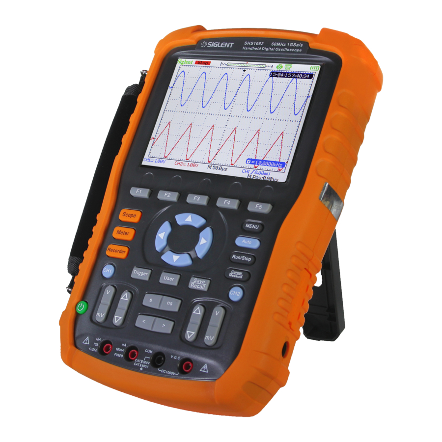
Page 17: Front Panel Introduction
Front Panel Introduction SHS1000 快速指南... - Page 18 Number Instruction Number Instruction Horizontal position/ Base scale control Menu control keys Trigger menu Menu display key Power key Auto set Channel 1 system Trigger level zero key User system Run/Stop control Recorder system Cursor measurement Multimeter system Horizontal position Save/Recall system zero key Vertical position/...
-
Page 19: Side Panel Introduction
Side Panel Introduction 1. USB Device This instrument can be connected to a printer for a print map of the current screen, or a PC for remote control via this port. 2. USB Host Files including setup file, waveform file, BMP file and CSV file can be saved to removable storage device via this port. -
Page 20: Oscilloscope Function Summary
User interface oscilloscope function system is shown below. User Interface 15 14 1. Logo Siglent is the registered trademark of SIGLENT TECHNOLOGIES., LTD. 2. Working State Available working states of the instrument are: Ready, Auto, Trig’d, Scan and Stop. SHS1000 快速指南... - Page 21 3. Waveform Memory Display position of the current waveforms in the oscilloscope memory. Waveforms displayed on the screen 4. Trigger Position Display trigger position of waveforms both in the memory and on the screen. 5. Print Display the current option of “Print Key” under the “Print Setup” menu.
- Page 22 9. Trigger Level Display the vertical position of the trigger level. 10. Trigger Position Display the horizontal trigger position of current waveforms. Use horizontal displacement control key to modify the parameter. Press right/left arrow key to make the arrowhead move right/left trigger displacement...
- Page 23 the lower left corner of the screen, or nothing displayed. When the vertical scale changes to 2mV/div, the “BW Limit” is automatically turned on. 15. Voltage Scale Represent the voltage value of each grid on the vertical axis of the screen. Use the voltage scale control key to modify the parameter, which is adjustable from 2mV to 5V.
-
Page 24: Function Introduction
Function Introduction Function Menu Scope Press the key to enter oscilloscope function system, as shown below: Acquire Press the corresponding menu key to enter Acquire system, under which there are three selectable waveform acquisition modes: Sampling, Peak Detect and Average. Display Press the corresponding menu key to enter Display system, under which functions like display type, persist time, wave intensity and brightness are easy to set. -
Page 25: Trigger Setting
Trigger setting Trigger Press the button to enter trigger system, under which five types of trigger including edge, pulse, video, slope and alternative are available, and each of them can be set in auto, normal or single mode. System setting Press the button to enter user system, under which the User system status and auxiliary functionalities like buzzer, language... -
Page 26: Auto Setting
Auto setting Auto Press the button to enable the waveform auto setting function. The instrument will automatically adjust its horizontal time base, vertical scale and trigger mode according to the input signal to make the waveforms displayed in a perfect state. Menu setting Menu Press the button to make the current menu displayed or... -
Page 27: Multimeter Function Summary
Multimeter Function Summary User Interface Meter Press the button to enter multimeter function system, under which 8 types of parameters including DC voltage, AC voltage, resistor, diode, continuity, capacitance, DC current and AC current are selectable to measure. Multimeter Interface 1. - Page 28 2. Connection Diagram Displayed on the screen based on the parameter you select to show you correct connecting method. 3. DC/AC Mark If a DC parameter (DC voltage or DC current) is selected, the mark “DC” displayed at the upper right corner of the screen; If a AC parameter (AC voltage or AC current) is selected, the mark “AC”...
-
Page 29: Measurement Parameters
Measurement Parameters There are 8 measurement parameters under multimeter function system. Read the following table carefully to know clearly about these parameters. Parameter The maximal Relative Operation Unit range DC voltage 0~1000V On/Off Manual/Auto V/mV AC voltage 0~750V On/Off Manual/Auto V/mV Resistor 0~60MΩ... -
Page 30: Recorder Function Summary
Recorder Function Summary The recorder function of the instrument includes Scope Trend Plot, Scope Recorder and Meter Trend Plot. Here are description for Trend Plot and Scope Recorder: Trend Plot Curve of measured value change with time. Observing the trend plot will make you a better prediction of change trend of the current parameter. - Page 31 Press Recorder → Scope Trend Plot to enter the interface shown above, under which you could set the wanted parameter. 1. Record Time The time from the beginning of drawing the scope trend plot to now. 2. Data Percentage The percentage of the recorded data occupied the total storage data.
-
Page 32: Scope Recorder
Scope Recorder Press Recorder → Scope Recorder to enter the interface shown below: Under the menu of Option, you could set the Viewer, Record and Replay shown below. Submenu Option Instruction Waveforms of channel1/2 displayed on Split the upper/lower half screen. Viewer Full Screen Waveforms displayed in full screen. - Page 33 Record Time: time from the beginning of recording waveforms to now. Remain Time: the remaining recordable time. Notes: the recorder function is available only in scan time base (no less than 100ms). SHS1000 快速指南...
-
Page 34: Meter Trend Plot
Meter Trend Plot Press Recorder → Meter Trend Plot to enter the meter trend plot interface for corresponding setting. Or you can also press Meter to enter meter function interface, and select the wanted parameter for a corresponding curve by press the Trend Plot. 1. - Page 35 In normal mode, the latest generated graph is always displayed on the screen. In full screen mode, all generated graph from beginning are displayed. 5. Data/Time Reflect the relationship between the measured value and the record time, which is defined as time of the intersection of the vertical scale and the scope trend curve.
-
Page 36: Troubleshooting
(2) Check if the power switch is faulted. (3) Check if the battery is electronic. (4) Restart the instrument after completing inspections above. (5) If it still does not work normally, please contact SIGLENT. 2. After the signal is sampled, there is no corresponding waveform displaying: (1) Check if the probe is correctly connected to the signal connecting cord. - Page 37 matches with the attenuation ratio of the probe. 4. There is waveform displaying but not stable: (1) Check the trigger source: check whether the “Source” in menu of “TRIG” is the actual operating channel. (2) Check if the waveform is wrong: it is easy for us to regard the wrong waveform as the real when a high frequency signal is connected to the instrument.
- Page 38 (1) Check if the current measurement range is appropriate for the measured value; (2) Check if the instrument exceeds its calibration period, and contact SIGLENT for new calibration if necessary. Data measured beyond the calibration period are inaccurate. (3) If the instrument can not work normally either, please contact SIGLENT.
-
Page 39: Contact Siglent
Contact SIGLENT SIGLENT TECHNOLOGIES CO., LTD Address:3/F, building NO.4, Antongda Industrial Zone, 3rd Liuxian Road, Bao’an District, Shenzhen, P.R.China Tel:0086-755-3661 5186 E-mail:sales@siglent.com http://www.siglent.com SHS1000 快速指南...
Need help?
Do you have a question about the SHS1000 Series and is the answer not in the manual?
Questions and answers