Table of Contents
Advertisement
Quick Links
Advertisement
Table of Contents

Related Manuals for SIGLENT SDS1204X HD


Summary of Contents for SIGLENT SDS1204X HD
- Page 1 SDS1000X HD Series Digital Oscilloscope User Manual EN01B...
-
Page 3: Table Of Contents
SDS1000XHD Series User Manual Contents Introduction ......................1 Important Safety Information ................2 General Safety Summary ....................2 Safety Terms and Symbols ....................4 Working Environment ......................5 Cooling Requirements ......................6 Power and Grounding Requirements ................. 6 Cleaning ..........................7 Abnormal Conditions ...................... - Page 4 SDS1000X HD Series User Manual Front Panel Overview ......................21 Rear Panel Overview ......................22 Connecting to External Devices/Systems ................. 23 6.3.1 Power Supply ......................23 6.3.2 LAN .......................... 23 6.3.3 USB Peripherals ...................... 23 6.3.4 Auxiliary Output ....................... 23 6.3.5 Waveform Generator ....................
- Page 5 SDS1000XHD Series User Manual 11 Vertical Setup ....................... 44 11.1 Turn on/off a Channel ......................44 11.2 Channel Setup........................45 12 Digital Channels ....................50 12.1 Overview ........................... 50 12.2 Enable/Disable the Digital Channels ................51 12.3 Digital Channel Setup ....................... 52 12.4 System ..........................
- Page 6 SDS1000X HD Series User Manual 15.5.12 Nth Edge Trigger ..................... 86 15.5.13 Delay Trigger ......................87 15.5.14 Setup/Hold Trigger ....................87 15.5.15 Serial Trigger ......................87 15.6 Trigger Source ........................88 15.7 Holdoff ..........................88 15.8 Trigger Coupling ........................ 89 15.9 Noise Reject ........................
- Page 7 SDS1000XHD Series User Manual 17.1 Overview .......................... 112 17.2 Select and Move Cursors ....................118 18 Measurement ...................... 120 18.1 Overview ......................... 120 18.2 Set Parameters ....................... 121 18.3 Type of Measurement ..................... 124 18.3.1 Vertical Measurement .................... 124 18.3.2 Horizontal Measurement ..................126 18.3.3 Miscellaneous Measurements ................
- Page 8 SDS1000X HD Series User Manual 19.5 Frequency Analysis ......................147 19.6 Formula Editor ......................... 155 20 Reference ......................157 21 Search ......................... 159 22 Navigate ......................161 23 Mask Test ......................166 23.1 Overview ......................... 166 23.2 Mask Setup ........................167 23.2.1 Create Mask ......................
- Page 9 SDS1000XHD Series User Manual 26.3 Display ..........................194 26.4 Data Analysis ........................196 27 Display ........................ 199 28 Arbitrary Waveform Generator ................. 206 28.1 Overview ......................... 206 28.2 Output ..........................207 28.3 Wave Type ........................207 28.4 Other Setting ........................208 28.5 System ..........................
- Page 10 SDS1000X HD Series User Manual 30.8.4 LXI.......................... 231 31 Remote Control ....................232 31.1 Web Browser ........................232 31.2 Other Connectivity ......................233 32 Troubleshooting ....................234 V I I I i n t . s i g l e n t . c o m...
-
Page 11: Introduction
The series includes the following models: Analogy Analog Model Maximum Sampling Rate Bandwidth Channel SDS1204X HD 200 MHz 2 GSa/s @ each channel SDS1104X HD 100 MHz 2 GSa/s @ each channel SDS1074X HD 70 MHz... -
Page 12: Important Safety Information
SDS1000X HD Series User Manual Important Safety Information This manual contains information and warnings that must be followed by the user for safe operation and to keep the product in a safe condition. General Safety Summary Carefully read the following safety precautions to avoid personal injury and prevent damage to the instrument and any products connected to it. - Page 13 SDS1000X HD Series User Manual Identification of Normal State of Equipment. After the equipment is started, there will be no alarm information and error information at the interface under normal conditions. The curve of the interface will scan from left to right freely; if there is a pop- up window or button during the scanning process or there is an alarm or error prompt, the device may be in an abnormal state.
-
Page 14: Safety Terms And Symbols
SDS1000X HD Series User Manual Safety Terms and Symbols When the following symbols or terms appear on the front or rear panel of the instrument or in this manual, they indicate special care in terms of safety. This symbol is used where caution is required. Refer to the accompanying information or documents to protect against personal injury or damage to the instrument. -
Page 15: Working Environment
SDS1000X HD Series User Manual Working Environment The design of the instrument has been verified to conform to EN 61010-1 safety standard per the following limits: Environment The instrument is used indoors and should be operated in a clean and dry environment with an ambient temperature range. -
Page 16: Cooling Requirements
SDS1000X HD Series User Manual Degree of Pollution The oscilloscopes may be operated in environments of Pollution Degree II. Note: Degree of Pollution II refers to a working environment that is dry and non-conductive pollution occurs. Occasional temporary conductivity caused by condensation is expected. IP Rating IP20 (as defined in IEC 60529). -
Page 17: Cleaning
SDS1000X HD Series User Manual a standard IEC320 (Type C13) connector for making line voltage and safety ground connections. The AC inlet ground terminal is connected directly to the frame of the instrument. For adequate protection against electrical shock hazards, the power cord plug must be inserted into a mating AC outlet containing a safety ground contact. -
Page 18: Safety Compliance
SDS1000X HD Series User Manual Proper use of the instrument depends on the careful reading of all instructions and labels. Warning: Any use of the scope in a manner not specified by the manufacturer may impair the instrument’s safety protection. This instrument should not be directly connected to human subjects or used for patient monitoring. -
Page 19: Informations Essentielles Sur La Sécurité
SDS1000X HD Series User Manual Informations essentielles sur la sécurité Ce manuel contient des informations et des avertissements que les utilisateurs doivent suivre pour assurer la sécurité des opérations et maintenir les produits en sécurité. Exigence de Sécurité Lisez attentivement les précautions de sécurité ci - après afin d 'éviter les dommages corporels et de prévenir les dommages aux instruments et aux produits associés. - Page 20 SDS1000X HD Series User Manual électrique doit être retirée pendant l'entretienLa ligne ne doit pas être mise sous tension tant que l'entretien de l'équipement n'est pas terminé et que l'entretien n'est pas confirmé. Identification de l'état normal de l'équipement. Après le démarrage de l'équipement, dans des conditions normales, il n'y aura pas d'information d'alarme et d'erreur au bas de l'interface, et la courbe de l'interface sera balayée librement de gauche à...
-
Page 21: Termes Et Symboles De Sécurité
SDS1000X HD Series User Manual Remplacer la batterie dans l 'appareil avec les mêmes spécifications de batterie au lithium. Termes et symboles de sécurité Lorsque les symboles ou termes suivants apparaissent sur le panneau avant ou arrière de l'instrument ou dans ce manuel, ils indiquent un soin particulier en termes de sécurité. Ce symbole est utilisé... -
Page 22: Environnement De Travail
SDS1000X HD Series User Manual Environnement de travail La conception de l'instrument a été certifiée conforme à la norme EN 61010-1, sur la base des valeurs limites suivantes: Environnement L'instrument doit être utilisé à l'intérieur dans un environnement propre et sec dans la plage de température ambiante. -
Page 23: Exigences De Refroidissement
SDS1000X HD Series User Manual La catégorie II d'installation (surtension) désigne le niveau local de distribution d 'énergie d' un équipement conçu pour accéder à un circuit alternatif (alimentation alternative). Degré de pollution Un oscilloscope peut être utilisé dans un environnement Pollution Degree II. Note: Pollution Degree II signifie que le milieu de travail est sec et qu'il y a une pollution non conductrice.Parfois, la condensation produit une conductivité... -
Page 24: Nettoyage
SDS1000X HD Series User Manual Remarque: l'instrument s'adapte automatiquement à l'entrée de ligne CA dans les plages suivantes: Plage de tension: 90 - 264 Vrms Gamme de fréquences: 47 - 63 Hz L'instrument comprend un jeu de cordons mis à la terre contenant une fiche polarisée à trois bornes moulée et un connecteur standard IEC320 (Type C13) pour établir la tension de ligne et la connexion de mise à... -
Page 25: Conditions Anormales
SDS1000X HD Series User Manual Conditions anormales Utilisez l'instrument uniquement aux fins spécifiées par le fabricant. N'utilisez pas la lunette s'il y a des signes visibles de dommages ou si elle a été soumise à de fortes contraintes de transport. Si vous pensez que la protection de l'oscilloscope a été... -
Page 26: First Steps
SIGLENT shall not be responsible for any defect, damage, or failure caused by any of the following: Attempted repairs or installations by personnel other than SIGLENT. -
Page 27: Document Conventions
SDS1000X HD Series User Manual Document Conventions For convenience, text surrounded by a box border is used to represent the button of the front panel. For example, Default represents the "Default" button on the front panel. Text with shading is used to represent the touchable or clickable menu/button/region on the touch screen. -
Page 28: Getting Started
SDS1000X HD Series User Manual Getting Started Mechanical Dimensions Front View Top View Adjust the Supporting Legs Adjust the supporting legs properly to use them as stands to tilt the oscilloscope upwards for stable placement as well as easier operation and observation of the instrument. i n t . -
Page 29: Power On
SDS1000X HD Series User Manual Power on SDS1000X HD provides two ways for power on, which are: Auto Power-on When the “Auto Power-on” option is enabled, once the oscilloscope is connected to the AC power supply through the power cord, the oscilloscope boots automatically. This is useful in automated or remote applications where physical access to the instrument is difficult or impossible. -
Page 30: System Information
SDS1000X HD Series User Manual System Information Follow the steps below to examine the software and hardware versions of the oscilloscope. Utility > Menu > System Info See the section “System Information” for details. Install Options A license is necessary to unlock a software option. See the section "Install Option" for details. i n t . -
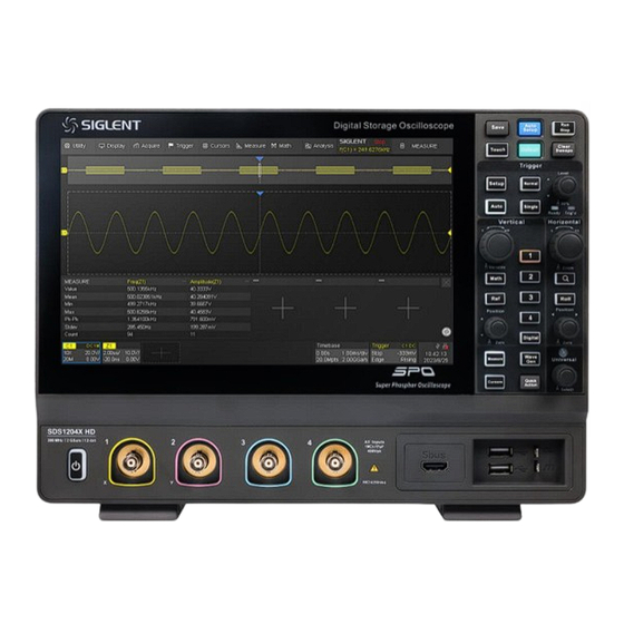
Page 31: Quick Start
SDS1000X HD Series User Manual Quick Start Front Panel Overview Touch Screen Display: The display and major functions area. See the "Touch Screen Display" chapter for more details Front Panel: Includes knobs and buttons. See the "Front Panel" chapter for more details Probe Compensation/ Ground Terminal: Supplies a 0-3 V, 1 kHz square wave for compensating the probes USB 2.0 Host Ports: Connect the USB host ports to USB storage devices for data transfer or a... -
Page 32: Rear Panel Overview
SDS1000X HD Series User Manual Rear Panel Overview Ext Trigger Input Auxiliary Out: Outputs the trigger indicator. When Mask Test is enabled, outputs the pass / fail signal 10M / 100M LAN Port: Connect the port to the network for remote control USB 2.0 Device Port: Connect with a PC for remote control USB 2.0 Host Port: Connect with a USB storage device or USB mouse/keyboard AC Power Input... -
Page 33: Connecting To External Devices/Systems
SDS1000X HD Series User Manual Connecting to External Devices/Systems Power Supply 6.3.1 The standard power supply for the instrument is 100~240 V, 50/60 Hz. Please use the power cord provided with the instrument to connect it to AC power. 6.3.2 Connect the LAN port to the network with a network cable with an RJ45 connector for remote control. -
Page 34: Probes
“Perfectly compensated” in the figure above. It’s not necessary to compensate active probes like the SIGLENT SAP series. i n t . s i g l e n t . c o m... -
Page 35: Logic Probe
SDS1000X HD Series User Manual Logic Probe 6.3.7 To connect the logic probe: The SLA1016 probe consists of five parts: the SLA1016 probe, the SUBS interface cable, the flat wire, the flying wire, and the probe clip. The installation is carried out as follows: Connect one end of the SUBS interface cable to the logical port of the SDS1000X HD and the other end to the interface of the SLA1016 probe;... -
Page 36: Touch Screen Display
SDS1000X HD Series User Manual Touch Screen Display Overview The entire SDS1000X HD display is a capacitive touch screen. Use your fingers to touch, drag, pinch, spread, or draw a selection box. Many controls that display information also work as “buttons” to access other functions. -
Page 37: Menu Bar
SDS1000X HD Series User Manual Trigger Level Line (Vertical) and Trigger Delay Indicator (Horizontal) show the trigger position of the waveform. Cursors show where measurement points have been set. Move the cursors to quickly reposition the measurement point. Channel Descriptor boxes include analog channels (Cn), digital channels (D), math (Fx), and reference (Ref). - Page 38 SDS1000X HD Series User Manual Display > Menu > Graticule There are multiple indicators on the grid: Trigger Level Indicator shows the level where the waveform triggers on the vertical axis. Trigger Delay Indicator locates where the waveform triggers on the horizontal axis... When the trigger position is outside the screen, the direction of the triangle points outside the screen as well.
-
Page 39: Channel Descriptor Box
SDS1000X HD Series User Manual Channel Descriptor Box Channel Descriptor boxes include analog channels (Cx), digital channels (D), zoom (Zx), math (Fx), and reference (Ref). They are located under the grid area, showing the parameters of the corresponding traces. Touching the boxes creates a dialog box. See chapter “Vertical Setup” for more details. -
Page 40: Timebase And Trigger Descriptor Boxes
SDS1000X HD Series User Manual Probe Attenuation Factor: Set the probe attenuation factor to match the actual attenuation of the probe. The oscilloscope automatically calculates the vertical scale according to the probe attenuation factor. For example, the vertical scale of the oscilloscope is 100mV/div with 1X attenuation, and 1V/div if the attenuation factor is changed to 10X. - Page 41 SDS1000X HD Series User Manual Trigger source Trigger coupling Trigger mode Trigger level Trigger type Trigger slope Trigger source C1~C4:Analog channels EXT: External trigger channel EXT/5:5x attenuation of external trigger channel AC Line: AC mains supply ...
-
Page 42: Dialog Box
SDS1000X HD Series User Manual Dialog Box The dialog box on the right side of the screen is the main area for setting the parameters of the selected function. Title bar. Touching the bar can hide the dialog box, and touching again can open the dialog box. Parameter setting area. - Page 43 SDS1000X HD Series User Manual Let’s use the operation of setting the “deskew” of a channel as an example: If the expected value is 65 ns, input “65” on the virtual keypad, and then choose the units n to complete the operation. On the virtual keypad, touching the button , and Default...
-
Page 44: Touch Gestures
SDS1000X HD Series User Manual Menu style = Embedded, and Dialog box is displayed Touch Gestures Waveforms, cursors, and trigger levels can be adjusted. Drag the waveform left and right to move it Pinch and spread the waveform horizontally on the horizontal axis to re-scale the timebase i n t . -
Page 45: Mouse And Keyboard Operation
SDS1000X HD Series User Manual Drag the waveform up and down to move it Pinch and spread the waveform vertically to on the vertical axis re-scale the vertical gain Touch and drag the cursor to move it Touch and drag the cursor information region to move the pair of cursors simultaneously Mouse and Keyboard Operation The SDS1000X HD user interface features mouse control as well as a touch screen. -
Page 46: Front Panel
SDS1000X HD Series User Manual Front Panel Overview The front panel is designed to operate the basic functions without having to open the software menu. Most of the front panel controls duplicate functionality available through the touch screen display but the operation is more quickly achieved. -
Page 47: Vertical Control
SDS1000X HD Series User Manual Vertical Control When a channel is disabled, push its channel button to turn it on. When a channel is turned on but not activated, push the button to activate it. When the channel is turned on and activated, push the button to disable it. -
Page 48: Horizontal Control
SDS1000X HD Series User Manual Horizontal Control Rotate to adjust the horizontal scale (time/div); push to enable Zoom; push again to switch between the main window and zoom window. Push to enable Zoom. Push again to exit Zoom mode. Push to enable horizontal Roll; push again to exit Roll mode. At time-base settings larger than 50 ms/div, it is recommended to set the oscilloscope to Roll mode so that the waveform is displayed in real-time. -
Page 49: Run/Stop Button
SDS1000X HD Series User Manual Run/Stop Button Press the button to switch the acquisition state between Run and Stop. When the state is Run, the button is illuminated in green. When the state is Stop, the button is illuminated in red. Auto Setup Button Auto Setup forces the oscilloscope to automatically set the vertical scale, horizontal scale, and trigger level according to the input signal to get optimum... -
Page 50: Other Buttons
SDS1000X HD Series User Manual Other Buttons Enables / Disables measurements and recalls the MEASURE dialog box. Performs a quick screenshot save or saves the currently save type file to the storage path. See the section “Save Button” for details. Enables/Disables the touch screen. -
Page 51: Multiple Approaches To Recall Functions
SDS1000X HD Series User Manual Multiple Approaches to Recall Functions The oscilloscope can recall functions through different approaches. Menu Bar If you are familiar with common computer programs, you may first choose to access a function by the drop-down menu from the menu bar at the top of the display. For example, to open the trigger setup dialog box, you can follow the steps below: Trigger >... -
Page 52: Shortcut Button On The Front Panel
SDS1000X HD Series User Manual Shortcut Button on the Front panel Most of the functions of the oscilloscope can be recalled directly by the shortcut buttons on the front panel. See the chapter "Front Panel" for details. To open the trigger setup dialog box, press the Setup button in the trigger control area on the front panel. -
Page 53: Quickly Capture The Signal
SDS1000X HD Series User Manual Quickly Capture the Signal This is an example of how to acquire a signal quickly. In this example, we assume the signal is connected to channel 1 and channel 1 is turned off. First, press the channel 1 button to turn on channel 1. The LED on the button lights and the descriptor box of channel 1 is displayed at the bottom of the screen. -
Page 54: Vertical Setup
SDS1000X HD Series User Manual Vertical Setup 11.1 Turn on/off a Channel From the Front Panel When a channel is disabled, push its channel button to turn it on. When a channel is turned on but not activated, push the button to activate it. When the channel is turned on and activated, push the button to disable it. -
Page 55: Channel Setup
SDS1000X HD Series User Manual 11.2 Channel Setup Touch the channel descriptor box, a quick dialog will pop up. Vertical scale and offset can also be set from this dialog box. Touch the region to set the vertical scale with the universal knob or virtual keypad ▲... - Page 56 SDS1000X HD Series User Manual Turn channel on/off Coupling (DC, AC or GND) Bandwidth limit (Full or 20 MHz) Probe settings including attenuation (1X, 10X, 100X or custom) and probe check Set the label text. Click to recall the label setting. Users can customize the text and display of the label Quickly apply a specified operation (Trigger, FFT, Simple Measure, Cursor, Search, Mask Test, Counter and Wave...
- Page 57 SDS1000X HD Series User Manual Probe Settings The SDS1000X HD provides 1X, 10X, 100X and custom probe attenuation factor options. The custom values can be between 10 . The oscilloscope will automatically convert the vertical scale according to the current probe attenuation factor. For example, the vertical scale of the oscilloscope under 1X attenuation is 100 mV/div, and the vertical scale will be automatically set to 1 V/div if the probe attenuation is changed to 10X.
- Page 58 SDS1000X HD Series User Manual 50 Ω: Suitable for high-frequency signals transmitted through 50 Ω coaxial cables or active probes. This can minimize the amplitude distortion caused by impedance mismatching. Warning: The 50 Ω input setting is not a high-power input. Damage can occur if the input exceeds the published specifications.
- Page 59 SDS1000X HD Series User Manual Before invert After invert Trace When the trace is hidden, the channel waveform is no longer displayed on the screen, while the acquisition is still running in the background. Trace visible Trace hidden i n t si gl en t. co m...
-
Page 60: Digital Channels
The equipment shall be used only for the purposes specified by the manufacturer. The SLA1016 probe is used only for SIGLENT's special series of oscilloscopes. Protection mechanisms can be compromised if the way the devices connected by the SLA1016 are not used for their intended purpose. -
Page 61: Enable/Disable The Digital Channels
SDS1000X HD Series User Manual digital logic probe, including waveform display, save, parameter measurement, etc. Trigger on a digital channel - Trigger with the digital channel as the trigger source, isolating events of interest. Decode on a digital channel - Serial protocol decoding of a digital channel requires the installation of the serial decode option. -
Page 62: Digital Channel Setup
SDS1000X HD Series User Manual From the Touch Screen Click + at the bottom of the display and select the “Digital” to turn it on. Click the digital channel descriptor box, and select Off on the pop-up menu to turn it off. Refer to the operation in the chapter “Vertical Setup”... - Page 63 SDS1000X HD Series User Manual The quick menu only covers the height range and position of the digital channels display area. More settings can be found in the dialog box. A. Turn on/off the digital channels. B. Labels can be set to data, address, or custom characters. C.
- Page 64 SDS1000X HD Series User Manual The configurable logical level includes TTL, CMOS, LVCMOS 3.3 V, LVCMOS 2.5 V, and Custom. The setting range of the custom threshold is -8.0 V to + 8.0 V. Bus Setting Press the Digital button on the front panel or touch the Digital descriptor box on the bottom to open the Digital dialog box, touch Bus to open the Digital Bus dialog box.
-
Page 65: System
SDS1000X HD Series User Manual 12.4 System System Info – Includes Software Version,Uboot-OS Version, FPGA Version,Serial Number and Hardware Version of the SLA1016 probe. i n t si gl en t. co m... - Page 66 SDS1000X HD Series User Manual Upgrade The firmware here refers to the firmware of the SLA1016 probe. The SDS1000X HD supports firmware and configuration file upgrades for the SLA1016 via a U disk. Follow the steps below: Copy the upgrade file (*.ADS) to the U disk. Insert the U disk to one of the USB host ports of the oscilloscope.
-
Page 67: Horizontal And Acquisition Setup
SDS1000X HD Series User Manual Horizontal and Acquisition Setup 13.1 Timebase Setup The timebase setup is used to adjust the scale and offset of the X (horizontal) axis. This setting applies to all analog, digital channels, and all math traces except FFT. Touch the timebase descriptor box and the quick menu of the timebase settings will pop up. -
Page 68: Acquisition Setup
SDS1000X HD Series User Manual 13.2 Acquisition Setup 13.2.1 Overview Touch Acquire Menu on the quick menu of the timebase settings, or touch the menu bar Acquire > Menu to recall the Acquire dialog box on the right side. A. Select the interpolation mode. B. - Page 69 SDS1000X HD Series User Manual X Interpolation Sinc Interpolation Acq Mode: “Fast” is the default setting. The SDS1000X HD provides a very high waveform update rate in fast mode. "Slow" mode will slow down the waveform update on purpose. Memory Depth: The memory depth that can be supported. According to the formula "acquisition time = sample points x sample interval", setting a larger memory depth can achieve a higher sample rate for a given time base, but more samples require more processing time, degrading the waveform update rate.
-
Page 70: Acquisition
SDS1000X HD Series User Manual 13.2.2 Acquisition The acquisition mode is used to determine how to acquire and process the signal. Normal: The oscilloscope samples the signal with equal time intervals. For most waveforms, the best display effect can be obtained using this mode. Peak Detact: Peak detect mode. -
Page 71: Roll Mode
SDS1000X HD Series User Manual Note: The maximum memory here is the upper limit of the memory space allocated by the oscilloscope. The actual sample points are related to the current time base and may be less than memory depth. The actual sample points information can be obtained in the timebase descriptor box (see the section "Timebase and Trigger Descriptor Boxes"... - Page 72 SDS1000X HD Series User Manual Sequence mode is a fast acquisition mode, which divides the memory depth into multiple segments (up to 80,000), each of which stores a single shot. In sequence mode, the oscilloscope only acquires and stores data without processing and displaying, until the specified segments are acquired. As a result, the dead time between trigger events is minimized, thus greatly improving the waveform update rate.
- Page 73 SDS1000X HD Series User Manual In normal mode, 3 pulses can be obtained on the screen with the sample rate of 2GSa/s at the maximum memory depth. Set the trigger mode to "Single", the timebase to 100 ns/div. Turn on the Sequence mode, and set the segments to maximum (45976 in this example, up to 80,000 depending on the number of samples at the current time base).
-
Page 74: History
SDS1000X HD Series User Manual In the example, 45976 pulses can be obtained with the sample rate of 2 GSa/s at the maximum memory depth. 13.3 History Touch Analysis > History to recall the history dialog box. A. Turn on or off history mode B. - Page 75 SDS1000X HD Series User Manual The oscilloscope automatically stores acquired frames. It can store up to 80,000 frames but the number may vary due to the memory depth and timebase settings. Turn on history mode, then the stored frames can be recalled and measured. Continue with the example in the section above.
- Page 76 SDS1000X HD Series User Manual Acq Time label Delta T label In addition to manually specifying a frame, history mode supports autoplay: Press the softkey to replay the waveform from the current frame to the first. Press the softkey to stop replay. Press the softkey to replay the waveform from the current frame to the last.
-
Page 77: Zoom
SDS1000X HD Series User Manual Zoom The SDS1000X HD supports waveform zoom in the horizontal and vertical directions. Press down the horizontal knob or the button on the front panel to turn on the zoom function. When the Zoom function is on, the waveform area is divided into upper and lower parts. The area of about 1/3 height above is the main window, and the area of about 2/3 height below is the zoom window. - Page 78 SDS1000X HD Series User Manual When the zoom window is activated, the zoom area can be expanded or compressed by rotating the horizontal and vertical scale knob. Rotating the horizontal and vertical position knob to move the position of the region. When the main window is activated, the scale knobs and position knobs are used to change the scale and delay/offset of the main window.
- Page 79 SDS1000X HD Series User Manual Adjust the horizontal scale of the Zoom window by horizontal pinch and spread in the zoom area of the main window or the Zoom window Adjust the vertical scale of the Zoom window by vertical pinch and spread in the zoom area of the main window or the Zoom window.
-
Page 80: Trigger
SDS1000X HD Series User Manual Trigger 15.1 Overview The oscilloscope only acquires waveforms of interest (i.e. the ones that satisfy the trigger condition) and aligns all trigger events at the trigger position to form a stable waveform display. The trigger is one of the most important features of an oscilloscope since we can only analyze a signal that we can trigger reliably and stably. -
Page 81: Trigger Setup
SDS1000X HD Series User Manual 15.2 Trigger Setup Touch the trigger descriptor box to display the quick menu of trigger settings. The trigger setup dialog box is displayed on the right side of the screen. A. Touch the level region and rotate the Level knob on the front panel to adjust the trigger level;... -
Page 82: Trigger Level
SDS1000X HD Series User Manual Trigger Related Label Trigger level Indicator Horizontal 0 position Indicator Horizontal 0 position (out of screen) Indicator 15.3 Trigger Level Both analog and digital triggers must have a correct trigger level value. The oscilloscope judges whether a waveform satisfies the trigger condition when it crosses the trigger level. - Page 83 SDS1000X HD Series User Manual Note: In Auto mode, if the signal satisfies the trigger conditions but cannot trigger the oscilloscope stably, it may be that interval between two trigger events exceeds the timeout period. Try Normal mode in this case. Normal: Triggers and acquisitions only occur when the trigger conditions are met.
-
Page 84: Trigger Type
SDS1000X HD Series User Manual 15.5 Trigger Type 15.5.1 Overview The trigger modes of the SDS1000X HD are digital designs. Compared with analog trigger circuits, digital triggers can not only greatly optimize trigger precision and trigger jitter, but also support multiple trigger types and complex trigger conditions. -
Page 85: Edge Trigger
SDS1000X HD Series User Manual 15.5.2 Edge Trigger Edge trigger distinguishes the trigger points by seeking the specified edge (rising, falling, alternating) and trigger level. The trigger source and slope can be set in the trigger dialog box. Touch the Source area to select trigger source, and touch the Slope area to select rising, falling, or alternating. - Page 86 SDS1000X HD Series User Manual Adjust Upper/Lower Level The slope trigger requires upper and lower trigger levels. When the trigger type is slope trigger, touch the trigger descriptor box, and the pop-up quick menu will show two levels. The upper/lower level can be set in the following two ways: Touch the Level Upper area in the quick menu to select the upper level, and then set the level value by the virtual keypad or the Level knob on the front panel.
-
Page 87: Pulse Trigger
SDS1000X HD Series User Manual 15.5.4 Pulse Trigger Trigger on a positive or negative pulse with a specified width. Trigger source, polarity (positive, negative), limit range, and time value can be set in the trigger dialog box. Less than a time value (<=) -- Trigger when the positive or negative pulse time of the input signal is lower than the specified time value. -
Page 88: Video Trigger
SDS1000X HD Series User Manual 15.5.5 Video Trigger Video trigger can be used to capture the complicated waveforms of most standard analog video signals. The trigger circuitry detects the vertical and horizontal interval of the waveform and produces a trigger based on the video trigger settings you have selected. The SDS1000X HD supports standard video signals for NTSC (National Television Standards Committee), PAL (Phase Alternating Line), HDTV (High Definition Television), and a custom video signal trigger. - Page 89 SDS1000X HD Series User Manual In the custom video trigger type, the corresponding "Of Fields" varies with the selection of the “Interlace” ratio. Therefore, the number of fields selected and the number of lines corresponding to each field can also be varied. If the "Of Lines" is set to 800, the correct relationship between them is as follows: Of Lines Interlace...
- Page 90 SDS1000X HD Series User Manual Trigger on a Specific Line of Video Video trigger requires that any analog channel can be used as the trigger source with a synchronization amplitude greater than 1/2 grid. The example below sets to trigger on Field 1, Line 22 using the NTSC video standard.
-
Page 91: Window Trigger
SDS1000X HD Series User Manual select the required interlace ratio (assuming that the interlace ratio is 8:1). Then set the frame rate, select the number of lines and the number of fields. Touch the Sync to select the synchronization mode for the input signal: Select the "Any"... -
Page 92: Interval Trigger
SDS1000X HD Series User Manual To set window trigger via the Relative window type When the window trigger type is set to "Relative", touch the trigger descriptor box. The pop-up menu will show two user-defined parameters: “Level +/-Delta" and "Level Center". The above two parameters can be set in the following two ways: Select the parameter in the Level +/-Delta area of the quick menu, then set the parameter value by the virtual keypad or the Level knob on the front panel. -
Page 93: Dropout Trigger
SDS1000X HD Series User Manual Trigger source, slope (rising, falling), limit range, and time value can be set in the trigger dialog box. Holdoff, coupling, and noise reject can be set in interval trigger, see the sections "Holdoff", "Trigger Coupling" and "Noise Reject" for details. 15.5.8 Dropout Trigger Dropout trigger includes two types: Edge and State. -
Page 94: Pattern Trigger
SDS1000X HD Series User Manual A positive runt pulse across through the low level but not the high level. A negative runt pulse across through the high level but not the low level. Holdoff, coupling, and noise reject can be set in the runt trigger, see the sections "Holdoff", "Trigger Coupling"... -
Page 95: Qualified Trigger
SDS1000X HD Series User Manual Logic (AND, OR, NAND, NOR), source, limit range, and time value can be set in the trigger dialog box. Source Setting Touch the Source Setting area to recall the following dialog box and set up for each channel separately. -
Page 96: Nth Edge Trigger
SDS1000X HD Series User Manual Qualified Source Edge Trigger Source Trigger Qualified State = High Edge = Rising Position When the type is “Edge”, the oscilloscope triggers at the first edge after the specified edge (Rising or Falling) of the qualified source; when the type is “Edge with Delay”, a time limit condition is available. Qualified Source Edge... -
Page 97: Delay Trigger
SDS1000X HD Series User Manual 15.5.13 Delay Trigger A delay trigger is true when the edge of source B occurs after meeting the set conditions of source A and a user-defined delay time. The setting of source A is similar to that of the pattern trigger and can be used for logical "and"... -
Page 98: Trigger Source
SDS1000X HD Series User Manual 15.6 Trigger Source The trigger sources supported by each trigger type are different. See the table below for details: Trigger Type C1~C4 EXT, EXT/5 AC Line D0~D15 √ √ √ √ Edge √ Slope × ×... -
Page 99: Trigger Coupling
SDS1000X HD Series User Manual 15.8 Trigger Coupling The coupling setting of a trigger is only valid when the trigger source is C1~C4, EXT, or EXT/5. DC: All of the signal’s frequency components are coupled to the trigger circuit for high-frequency bursts or where the use of AC coupling would shift the effective trigger level. - Page 100 SDS1000X HD Series User Manual Noise Reject = On i n t . s i g l e n t . c o m...
-
Page 101: Serial Trigger And Decode
SDS1000X HD Series User Manual Serial Trigger and Decode 16.1 Overview The SDS1000X HD supports serial bus trigger and decoding on the following serial bus protocols: I2C, SPI, UART, CAN, LIN, FlexRay (decoding only) and CAN FD (decoding only). Press the Setup button on the front panel or touch the trigger descriptor box, and then select the Type as Serial in the trigger dialog box to set the serial trigger: A. - Page 102 SDS1000X HD Series User Manual Below are detailed descriptions of the trigger and decode steps for each protocol. I2C Trigger and Serial Decode SPI Trigger and Serial Decode UART Trigger and Serial Decode CAN Trigger and Serial Decode ...
-
Page 103: I2C Trigger And Serial Decode
SDS1000X HD Series User Manual 16.2 I2C Trigger and Serial Decode This section covers triggering and decoding I2C signals. Please read the following for more details: "I2C Signal Settings", "I2C Trigger" and "I2C Serial Decode". 16.2.1 I2C Signal Settings Connect the serial data signal (SDA) and the serial clock signal (SCL) to the oscilloscope, set the mapping relation between channels and signals, and then set the threshold level of each signal. -
Page 104: I2C Trigger
SDS1000X HD Series User Manual Copy Setting Touch the Protocol Copy in the decode dialog box to synchronize the settings between the trigger and decode. Copy the decode settings to trigger Copy the trigger settings to decode Return to the previous menu Note: The synchronization is not automatic. - Page 105 SDS1000X HD Series User Manual Restart — The oscilloscope will be triggered when another “Start” occurs before a “Stop". No Ack — The oscilloscope will be triggered when the SDA line is high during any SCL’s ACK bit. EEPROM — The trigger searches for EEPROM control byte value 1010xxx on the SDA bus.
- Page 106 SDS1000X HD Series User Manual Frame (Start: 7-bit address: R/W: Ack: Data: Ack: Data2)—If all bits match, then trigger on the Ack bit followed by the Data2. 10 Address & Data — If all bits match, then trigger on the Ack bit followed by the Data. Frame (Start: Address 1st byte: R/W: Ack: Address 2nd byte: Ack: Data) i n t .
- Page 107 SDS1000X HD Series User Manual If you set the trigger condition to 7 address & data or 10 address & data: Address can be selected in the hexadecimal range of 0x00 to 0x7F (7-bit) or 0x3FF (10-bit). If the address is selected as "0xXX (7-bit address)"...
-
Page 108: I2C Serial Decode
SDS1000X HD Series User Manual 16.2.3 I2C Serial Decode The layout of the touch screen display when I2C decode is enabled is as follows: A. The waveform display area shows the original waveforms of the bus signals. B. The bus display shows the decoding result of the bus. At most two buses can be decoded at the same time. -
Page 109: Spi Trigger And Serial Decode
SDS1000X HD Series User Manual List TIME — The horizontal offset of the current data frame head relative to the trigger position. Address — Address value. For example, "0x2AB" means that address = 2AB with acknowledgement. R/W — Read address or write address. ... - Page 110 SDS1000X HD Series User Manual between channels and signals. Then set the threshold level of each signal. The process of specifying the source and threshold is similar to "I2C Signal Settings". In addition to specifying the source and the threshold level, for the CLK signal, it is also necessary to specify the Edge Select .
- Page 111 When the CS type is set to CLK Timeout, turn on Cursor, measure the clock idle time between frames as 505 us, and measure the interval between clock pulses as 0.5 us, then set the timeout to a value between 0.5 us and 505 us. In this example it is set to 4.5 us: int siglent.com...
-
Page 112: Spi Trigger
SDS1000X HD Series User Manual If the data width is set to be greater than 8 bits (such as 16 bits), measure the clock idle time between 8-bit data packets as 5.05 us, and then set the timeout time to a value between 5.05 and 500 us. In this example, it is set to 80 us: 16.3.2 SPI Trigger The trigger condition for the SPI trigger is mainly about data. -
Page 113: Spi Serial Decode
Select the number of stop bits Set the idle level Set the bit order G. Return to the previous menu The method of copying settings is the same as I2C signal settings. See "I2C Signal Settings" for details. int siglent.com... -
Page 114: Uart Trigger
SDS1000X HD Series User Manual 16.4.2 UART Trigger Touch Trigger Setting in the dialog box to set the trigger condition: Source Type: RX or TX Trigger Condition: Start, Stop, Data or Error When the "trigger condition" is Data, set the compare type to =, >, <... -
Page 115: Can Signal Settings
ID + Data —The oscilloscope triggers on the data frame that matches the specified ID and data.ID, ID Bits (11-bit or 29-bit), Curr ID Byte (1st, 2nd, 3rd, or 4th byte), Data1, and Data2 can be set. Error—The oscilloscope triggers on the error frame. int siglent.com... -
Page 116: Can Serial Decode
SDS1000X HD Series User Manual 16.5.3 CAN Serial Decode The configuration of CAN decoding is similar to that of I2C decoding. On the bus: ID is displayed in green. LEN (data length) is displayed in light yellow. DATA are displayed in white. -
Page 117: Lin Trigger And Serial Decode
ID —The oscilloscope triggers on the frame that matches the specified ID, which ranges from 0x00 to 0x3f. ID & Data—The oscilloscope triggers on the frame that matches the specified ID and data.ID, Data1, and Data2 can be set. Data Error —The oscilloscope will trigger when a data error happens. int siglent.com... -
Page 118: Lin Serial Decode
SDS1000X HD Series User Manual 16.6.3 LIN Serial Decode The configuration of LIN decoding is similar to that of I2C decoding. On the bus: ID is displayed in green. LEN (data length) and CHK are displayed in blue. ... -
Page 119: Flexray Serial Decode
FCRC (Data Check Code) is displayed in the frame and displayed in blue. In the list view: Time -- The horizontal offset of the current data frame head relative to the trigger position. FID -- Frame ID, the symbol occupies a single line of the list. int siglent.com... -
Page 120: Can Fd Serial Decode
SDS1000X HD Series User Manual PL -- Valid Data Length. HCRC -- Head Check Code. CYC -- Cycle count. Data -- Data values. FCRC -- Data Check Code. 16.8 CAN FD Serial Decode 16.8.1 CAN FD Signal Settings Connect the CAN FD signal to the oscilloscope, and then set the threshold level of the signal. - Page 121 "FD", the extended frame is represented by "Ext" and the remote frame is represented by "RTR". ID -- Frame ID. Length -- Data length. Data -- Data bytes. CRC -- Cycle redundancy check. Ack -- Acknowledge bit. int siglent.com...
-
Page 122: Cursors
SDS1000X HD Series User Manual Cursors 17.1 Overview Cursors are important tools when measuring signals. Rapid measurements can be performed using cursors in both horizontal and vertical directions. The cursor types include X1, X2, X1-X2, Y1, Y2, and Y1-Y2, used to indicate X-axis values (time or frequency) and Y-axis values (amplitude) on a selected waveform (CH1/CH2/CH3/CH4/F1/F2/F3/F4/REF). - Page 123 Track -- The cursor type is automatically set to "horizontal + vertical". In this mode, only horizontal cursors are adjustable, while the vertical cursors automatically attach to the cross-point of the cursor and the source waveform. Measure -- Automatically indicates the measured item using cursors. Manual Mode Track Mode int siglent.com...
- Page 124 SDS1000X HD Series User Manual Measure Mode Cursors Type X (horizontal) -- Vertical dotted lines that measure horizontal time (when the source is an FFT waveform, X cursors measure frequency). X cursors (time) X cursors (frequency) X1 — The left (default) vertical dotted line. It can be manually moved to any horizontal position on the screen.
- Page 125 Y1- Y2 — The difference between Y1 and Y2. After this option is selected, turn the universal knob to move both Y1 and Y2 simultaneously. X+Y (horizontal + vertical) -- Both the X cursors and Y cursors are enabled. Display Mode Display Mode Following Display Mode Fixed int siglent.com...
- Page 126 SDS1000X HD Series User Manual Followling – The position information of each cursor is attached to the cursor, and the difference information is between the two cursors with arrows connected to the cursors. This mode is more intuitive. Fixed -- The position information of each cursor and the difference between the cursors are displayed in a region on the screen.
- Page 127 The value of X1 and X2 is changed to -100 ns, 200 ns. Fixed delay, timebase is changed to 100 ns/div, the value of X cursors (-50 ns, 100 ns) remains fixed. The grid number of X cursors is changed to -0.5div, 1div. int siglent.com...
-
Page 128: Select And Move Cursors
SDS1000X HD Series User Manual 17.2 Select and Move Cursors The cursors can be selected and moved directly by gestures and the universal knob on the front panel, in addition, they can be selected in the cursor’s value dialog box. Gestures Directly touch the cursor and drag it, as shown below: Touch the display area of △X (or △Y) in Following mode and drag it to move the two cursors... - Page 129 You can use both in combination to suit your needs: First, a rough adjustment is achieved by using gestures, and then the fine adjustment is achieved by using the universal knob. Dialog Box Touch the cursor value area of the dialog box, and then rotate the universal knob to adjust the position. int siglent.com...
-
Page 130: Measurement
SDS1000X HD Series User Manual Measurement 18.1 Overview The SDS1000X HD features a strong automatic measurement list. These parameters can be automatically measured without cursors and include common measurements such as rise time, fall time, peak-peak, and period. The SDS1000X HD can also measure multiple channels at the same time, showing up to 5 parameter measurements with statistics while in the M1 display mode and up to 12 parameters in the M2 mode. -
Page 131: Set Parameters
G. Turn on or off statistics Statistics settings: count limit, AIM limit, reset statistics and histogram 18.2 Set Parameters Touch Type in the measure dialog box, or touch in the measurement parameters and statistics display area to open the parameter selection window: int siglent.com... - Page 132 SDS1000X HD Series User Manual Set the source of the current setting. Measurement parameter classification tabs, including Favorite, Vertical, Horizontal, Miscellaneous, and CH Delay. Touch a tab and in the area will display the corresponding parameters Parameters. Touch the parameter to be measured to activate it, and touch it again to close the parameter.
- Page 133 Long-press an item to add or remove it from the “Favorite” tab. For example, to add Pk-Pk to the “Favorite” tab: Advanced > Type > Vertical > Pk-Pk > Add to favorite To remove Period from the “Favorite” tab: Advanced > Type > Favorite > Period > Delete from favorite int siglent.com...
-
Page 134: Type Of Measurement
SDS1000X HD Series User Manual 18.3 Type of Measurement 18.3.1 Vertical Measurement Vertical measurement includes 19 parameters: Max: Highest value in the input waveform Min: Lowest value in the input waveform Pk-Pk: Difference between maximum and minimum data values ... - Page 135 Overshoot (ROV): Overshoot following a rising edge; 100%*(max-top)/amplitude Preshoot (FPRE): Overshoot before a falling edge. Equal to 100 %*( max-top)/amplitude. Preshoot (RPRE): Overshoot before a rising edge. Equal to 100 %*( base-min)/amplitude. L@T: Level measured at trigger position int siglent.com...
-
Page 136: Horizontal Measurement
SDS1000X HD Series User Manual 18.3.2 Horizontal Measurement Horizontal measurement includes 17 parameters: Period: Time between the middle threshold points of two consecutive like-polarity edges. Freq: Reciprocal of the period Time@max: First time of maximum value Time@min: First time of minimum value ... -
Page 137: Miscellaneous Measurements
Cycles: Number of cycles in a periodic waveform Rising Edges: Number of rising edges in a waveform Falling Edges: Number of falling edges in a waveform Edges: Number of edges in a waveform int siglent.com... -
Page 138: Delay Measurement
SDS1000X HD Series User Manual Ppulses: Number of positive pulses in a waveform Npulses: Number of negative pulses in a waveform PSlope: The slope of the rising edge NSlope: The slope of the falling edge 18.3.4 Delay Measurement Delay measurement measures the time difference between two channels. -
Page 139: Trend
Maximum value Minimum value G. Average value Count number Reset statistics Press the Clear Sweeps button or touch Reset Statistics in the measure dialog box, or touch the symbol in the statistics display area to clear and restart statistics. int siglent.com... -
Page 140: Track
SDS1000X HD Series User Manual 18.5 Track The measure values VS. time plot of a horizontal parameter (e.g. frequency, rise time) in one frame can be observed when the Track is enabled. The upper limit of the statistic number in a frame is set in Statistics Setting > AIM Limit , which means the values exceeding the limit will not be shown in the track plot. -
Page 141: Measurement Statistics
"Unlimited". The setting range is 1 ~ 25,000 Clear and restart the statistics. Pressing the Clear Sweeps button on the front panel has an equivalent effect Turn the histogram on or off Return to the previous menu int siglent.com... -
Page 142: Statistics Histogram
SDS1000X HD Series User Manual Enable the Statistics function to observe the distribution of the measured values of every selected parameter. Value – The current measurement Mean – Average of all historical measurements Min – The minimum of all historical measurements ... -
Page 143: Simple Measurements
Enabling Simple Measurement displays all selected measurement parameters of the specified channel at the same time. The font color of the measurement parameters is consistent with the color of the specified source. Yellow for Channel 1, Purple for Channel 2, etc. int siglent.com... -
Page 144: Gate
SDS1000X HD Series User Manual 18.10 Gate Sometimes the user may want to measure parameters for a certain specified time range of the signal and ignore signal parts that lie outside of that range. In this case, the Gate function can be helpful. Turn on the Gate , then two horizontal cursors A and B will appear in the grid area. -
Page 145: Amplitude Strategy
Period, frequency, +width, -width, +duty, -duty, +BWidth, -BWidth, delay, T@M, rise time, fall time, CCJ, cycles, rising edges, falling edges, edges, Ppulses, Npulses, and delay measurement. Touch Config > Threshold in the measure dialog box to recall the threshold dialog box: int siglent.com... -
Page 146: Hardware Frequency Counter
SDS1000X HD Series User Manual Set measurement threshold source Set the type of threshold Set the upper value Set the middle value Set the lower value Return to the previous menu Threshold Type Percent : Set according to the percentage of the waveform. The setting range of lower value and upper value is 1% ~ 99%, and the low value shall not be greater than the middle value and high value Absolute : Set according to the vertical range. -
Page 147: Math
V, A, or U* Subtraction (-) *(used when the units of two sources are not consistent) Multiplication (x) V^2, A^2, or W None, Ω (Resistance unit Ohms), S (conductance unit Siemens) Division (/) dBVrms, Vrms, dBArms, Arms, dBm int siglent.com... -
Page 148: Arithmetic
SDS1000X HD Series User Manual Identity (y) or V, A negation (-y) d/dt V/s (Volt/second) or A/s (A/second) ∫dt VS (Volt*second) or AS (A*second) √ V ^ 0.5 or A ^ 0.5 V, A Sign V, A Exp or Exp10 V, A Ln or lg V, A... -
Page 149: Identity / Negation
The following figure shows an example of F1 = -C1: 19.2.3 Average / ERES Average -- By averaging the channel waveforms sampled multiple times, random noise on the input signal is reduced. The higher the average number, the smaller the random noise int siglent.com... -
Page 150: Max-Hold / Min-Hold
SDS1000X HD Series User Manual ERES -- Reduce bandwidth random noise on the measured signal and improve signal-to-noise ratio by filtering the sampling points 19.2.4 Max-hold / Min-hold The value of Max-hold and Min-hold are based on statistical calculations from multiple frames. The following figure shows the Max-hold result. -
Page 151: Algebra
Setting Offset in the integral menu provides an approach to correct the DC offset of the source. Small DC offsets in the input signal (or even small offset errors of the oscilloscope itself) may cause the integral output waveform to "ramp" up or down, as shown below: Integral without Offset Integral with Offset int siglent.com... -
Page 152: Square Root
SDS1000X HD Series User Manual In addition, the integral operation can be performed within a specified gate. Touch the Gate area in the math dialog box, and enable the Gate function, then set Gate A and Gate B to define the gate. -
Page 153: Absolute
In mathematics, the sign function or signum function (from signum, Latin for "sign") is an odd mathematical function that extracts the sign of a real number. The sign function of a real number x is defined as follows: Sign(x) = -1 if x < 0, if x = 0, if x > 0. int siglent.com... -
Page 154: Exp10
SDS1000X HD Series User Manual 19.3.6 Exp10 The exponential operation includes the exponential operation �� �� based on constant e and the exponential operation 10 �� based on 10. For example: y(x) = �� �� 19.3.7 Lg Logarithmic operation includes logarithm base e (ln) and logarithm base 10 (lg). In logarithmic operation, if the waveform value is negative (the waveform is below the ground level), the result is displayed as zero. -
Page 155: Filter
Low pass, High pass, Band Pass, and Band Reject. The filters have up to 200 taps which can reach roll-off as fast as 0.01*fs. Users just need to set the filter type and corner frequency(s), then the instrument will automatically calculate the coefficients needed for the filtering. int siglent.com... - Page 156 SDS1000X HD Series User Manual Choose to let the scope set the sample rate automatically according to the filter setting or not. See below for details Filter type: Low pass, High Pass, Band Pass, and Band Reject Corner frequency. For Bandpass and Band Reject there are two corner frequencies, separately named Lower Frequency and Upper Frequency.
-
Page 157: Frequency Analysis
The result of FFT (Fast Fourier Transform) calculations is the frequency spectrum of the source signal. The horizontal axis of the FFT display is labeled using frequency (Hz) units instead of time (seconds). In addition, the vertical axis provides the option of logarithmic scaling (dBVrms/dBArms or dBm). int siglent.com... - Page 158 SDS1000X HD Series User Manual Time-domain waveform display area Spectrum (FFT) waveform display area FFT parameter display area Dialog box Parameter Display Area The FFT parameters are displayed in the upper right of the spectrum waveform display area: FFT sample rate (Sa): FFT operation results present the first Nyquist zone (DC ~ Sa/2) of the frequency spectrum.
- Page 159 Better frequency resolution 8π/N Hamming -43 dB 1.8 dB Poor amplitude resolution Poor frequency resolution 12π/N Blackman -58 dB 1.1 dB Better amplitude resolution The worst frequency resolution 23π/N Flattop -93 dB < 0.1dB The best amplitude resolution int siglent.com...
- Page 160 SDS1000X HD Series User Manual Display Mode Split: Time-domain waveform and frequency domain waveform are displayed separately. The time-domain waveform is on the upper half screen, while the frequency domain waveform is located within the lower half of the display. In Split mode, if Zoom is enabled, the zoomed waveform and the frequency domain waveform are displayed on the lower half screen together.
- Page 161 Touch Span to set the frequency span with the center frequency as the center by the universal knob or the virtual keypad. Touch Start to set the start frequency by the universal knob or the virtual keypad. Touch End to set the end frequency by the universal knob or the virtual keypad. int siglent.com...
- Page 162 SDS1000X HD Series User Manual The relationship between Center, Span, Start, and End is: Center = (Start + End)/2 Span = End – Start FFT Tools The SDS1000X HD provides two tools for the FFT waveform: Peaks and Markers. The peaks tool can automatically search the qualified peak points and mark them on the FFT waveform.
- Page 163 Set the difference between the peak value and the minimum amplitude on both sides. The difference should be greater than the search excursion, which can be determined as the peak Return to the previous menu int siglent.com...
- Page 164 SDS1000X HD Series User Manual Note: The FFT dialog box is longer than the display. Slide the dialog box area up and down by gestures, or scroll the mouse wheel to the view non-displayed areas. The following shows the peaks of the FFT waveform: Measure the FFT waveform Press the Cursors button on the front panel to turn on the cursor function, and then specify the source as "Math".
-
Page 165: Formula Editor
The keyboard area contains the basic arithmetic operators addition (+), subtraction (-), multiplication (*), division (/) Confirm button. After the formula is input, press the button to apply it The following is an example of F1 = (3*C1)+1V through the formula editor: int siglent.com... - Page 166 SDS1000X HD Series User Manual The following is an example of implementing nested operations between operators through the formula editor: In this example, F1=d (C1)/dt and F2=FFT (d (C1)/dt) are equivalent to F2=FFT (F1), which is equivalent to performing FFT analysis on the differential operation results of C1 waveform. 1 5 6 i n t .
-
Page 167: Reference
Select the location of the reference (REFA / REFB/ REFC / REFD) Select the source (C1~C4 and MATH) Enable/disable Display of the reference waveform Set the label text of the reference trace. Save the specified waveform in to the specified location in int siglent.com... - Page 168 SDS1000X HD Series User Manual Adjust the Reference Waveform Set the vertical position of the reference waveform by the offset knob on the front panel, and set the vertical scale of the reference waveform by the scale knob. 1 5 8 i n t .
-
Page 169: Search
Total number of events marked on the display The search dialog box, hidden in this example In the stop state, the area shows the index of the current event/total number of events. The current event is the one in the center of the display. int siglent.com... - Page 170 SDS1000X HD Series User Manual Touch the menu Analysis > Search recall the search dialog box and turn on it. Setup Menu Select and set the search type in the Setup Menu . The SDS1000X HD provides five search conditions: Edge, Slope, Pulse, Interval, and Runt. Search Type Setup Description Edge...
-
Page 171: Navigate
Touch Playing Mode to set the search event playing mode. Touch Interval Time to set the playing interval by the universal knob or the virtual keypad. int siglent.com... - Page 172 SDS1000X HD Series User Manual Touch the Event List Switch area to turn on or off the list. The list contains time labels for each event. Touching a row in the list automatically jumps to the corresponding event. This operation is equivalent to specifying an event in the Event Num area.
- Page 173 Set the horizontal scale to 10 ms/div, then 5 markers with ~20 ms interval are shown on the display, indicating that a total of 5 dwarf pulses were found in the full screen of 100 ms time range: int siglent.com...
- Page 174 SDS1000X HD Series User Manual Turn on the Zoom function to observe the full view of the frame and the detail of the third dwarf pulse at the same time: 1 6 4 i n t . s i g l e n t . c o m...
- Page 175 Press the Run/Stop button on the front panel to stop the acquisition, and then follow the steps Navigate > Type to select “Search Event”. The following figure shows the first dwarf pulse. In this example, the list is enabled and the time labels of a partial event are shown in the list. int siglent.com...
-
Page 176: Mask Test
SDS1000X HD Series User Manual Mask Test 23.1 Overview Users can create masks and define the rule used to evaluate Pass/Fail operations. An event violating the rule is defined as a failure and a pulse can be generated from the "Aux Out" port on the back panel. -
Page 177: Mask Setup
Create a mask automatically according to the waveform Create a custom mask using the Mask Editor tool Load the mask Return to the previous menu int siglent.com... -
Page 178: Create Mask
SDS1000X HD Series User Manual 23.2.1 Create Mask The mask can be created based on an existing waveform trace. Set the horizontal spacing of the mask around the currently displayed trace. The units are parts of the horizontal division setting. Set the vertical spacing of the mask around the currently displayed trace. - Page 179 New: Create a new mask file Open: Open an existed mask file Save: Save the current mask file Save As: Save the current mask file to the specified path Exit: Exit the Mask Editor tool int siglent.com...
- Page 180 SDS1000X HD Series User Manual Note: The mask file created by the “Create Mask” cannot be recalled by the Mask Editor. The contents of the Edit menu are equivalent to the Toolbar. Toolbar Draw: Creates vertices of a polygon by touching the display or entering values in coordinate edit area ...
-
Page 181: Pass/Fail Rule
Touch Operation to start/stop the test. Stopping a test in progress and restarting the test will clear the count of the passed frames, failed frames, total frames, and the fail rate. Pressing the Clear Sweeps button on the front panel can also clear the count information. int siglent.com... -
Page 182: Counter
SDS1000X HD Series User Manual Counter 24.1 Overview The counter is used to measure the frequency and period of a signal or count the events happening within it. The counter is asynchronous to the acquisition system of the oscilloscope. It can work well even if the acquisition of the oscilloscope is stopped (indicated by a red-colored Run/Stop button) Touch the menu Analysis >... -
Page 183: Mode
When the mode is set to totalizer, the edge of the counting source needs to be set. When the counting gate is turned on, the counter can count only when the gate-source meets the specified conditions. Touch Gate Setting to recall the gate setting dialog box: int siglent.com... - Page 184 SDS1000X HD Series User Manual Turn on or off the gate Select the gate type: Level or After Edge Gate source display area. C1 and C2 are gate sources of each other, C3 and C4 are gate sources of each other When the gate type is level, set the polarity (Positive or Negative) of the gate source.
-
Page 185: Power Analysis
Transient Response, PSRR, Power Efficiency, Output Ripple, etc. Full use of the Power analysis requires a differential voltage probe like the SIGLENT DPB series, a current probe like the SIGLENT CP series, the SIGLENT DF2001A deskew fixture, and the power analysis activation license (part number SDS1000XHD-PA). -
Page 186: Power Quality
SDS1000X HD Series User Manual 25.2 Power Quality The specific measurement parameters of power quality analysis include active power, apparent power, reactive power, power factor, power phase angle, voltage effective value, current effective value, voltage crest factor, and current crest factor of power input of a switching power supply. Type Power —... -
Page 187: Current Harmonics
25.3 Current Harmonics Current harmonics are used to analyze the input current harmonics. An FFT of the selected channel is performed to get the harmonic components. The signal settings and connection guide are the same as the power quality test. int siglent.com... - Page 188 SDS1000X HD Series User Manual Configuration Touch Config to recall the configuration dialog box: Set the frequency of the line (Auto, 50 Hz, 60 Hz, or 400 Hz) Set the standard type (IEC61000-3-2 A, IEC61000-3-2 B, IEC61000-3-2 C or IEC61000-3-2 D) Set the display type (Off, Bar Chart, or Table) Return to the previous menu Standard...
-
Page 189: Inrush Current
Set the maximum effective input voltage (Vrms), the range is 1 V ~ 1 kV. The oscilloscope will set the vertical scale of the voltage channel to maximum input voltage/6 View the connection guide Return to the previous menu int siglent.com... -
Page 190: Switching Loss
SDS1000X HD Series User Manual 25.5 Switching Loss Switch loss analysis can be used to calculate the power dissipated in the switching period. Deskew Calibration A relatively small skew can cause a large measurement error of switching loss, especially during the on phase when the voltage is close to zero and the non-on phase when the current is close to zero. - Page 191 Auto Deskew to perform the calibration. When the process completes, a message will pop up indicating whether the deskew operation was successful or not. Before deskew calibration After deskew calibration Configuration Touch Config to recall the configuration dialog box: int siglent.com...
- Page 192 SDS1000X HD Series User Manual Set the voltage reference, i.e. the switch level at the edge of the input switch. This value is a percentage of the maximum switching voltage. Adjusting the value to ignore background noise. This value is used to determine the threshold hysteresis of the switch edge Set the current reference, i.e.
-
Page 193: Slew Rate
Touch Input Setup > Connection Guide to recall the connection guide of modulation, as shown in the figure below. Please follow the instructions in this figure for connection. Touch the icon on the top right of the guide to close. int siglent.com... -
Page 194: Output Ripple
SDS1000X HD Series User Manual 25.8 Output Ripple Power supply ripple is an important parameter to evaluate DC power supply, which represents the quality of output DC voltage. Ripple analysis can measure the current value, average value, minimum value, maximum value, standard deviation, and count of the power supply output ripple. Connection Guide Touch Input Setup >... - Page 195 Touch Input Setup > Connection Guide to recall the connection guide of turn on/turn off, as shown in the figure below. Please follow the instructions in this figure for connection. Touch the icon on the top right of the guide to close. int siglent.com...
-
Page 196: Transient Response
SDS1000X HD Series User Manual 25.10 Transient Response Transient response analysis can determine the response speed of the output voltage of the power supply to the change of the output load. This time starts from the first time that the output voltage exits the stable band and ends at the last time that the output voltage enters the stable band. -
Page 197: Psrr
Measure the AC RMS ratio of input to output, and plot the relationship between the ratio and frequency. The background noise of the oscilloscope is higher than that of the network analyzer, and the sensitivity is lower than that of the network analyzer, so the PSRR int siglent.com... -
Page 198: Power Efficiency
SDS1000X HD Series User Manual measured by the oscilloscope is difficult to exceed -60 dB. The PSRR test is generally acceptable for sampling the overall PSRR behavior of the power supply under test. The configuration of PSRR is the same as that of the Bode plot, see the chapter "Bode Plot" for details. Connection Guide Touch Input Setup >... -
Page 199: Soa
Users can adjust horizontal, vertical, and trigger settings during the test for best observation. Below is an example of testing the power-up stresses on a MOSFET and judging if the stresses are safe for the MOSFET using the SOA: int siglent.com... - Page 200 SDS1000X HD Series User Manual Voltage and current waveforms on the MOSFET at power-up SOA, in which the mask is created according to the voltage limit, current limit, and power limit. The result shows “Pass” because all the stresses are within the mask. 1 9 0 i n t .
-
Page 201: Bode Plot
At this time, either the SIGLENT SAG1021I arbitrary waveform generator or one of a SIGLENT SDG series arbitrary function generators are supported. During the sweep, the oscilloscope configures the generator output frequency and amplitude and then compares the input signal to the output of the DUT. -
Page 202: Configuration
SDS1000X HD Series User Manual 26.2 Configuration 26.2.1 Connection DUT input and output channels Channel gain. When it is set to Auto, the oscilloscope will automatically adapt the vertical scale according to the signal amplitude; when it is set to Hold, it will always keep the vertical scale before the test operation Arbitrary waveform generator connection settings. - Page 203 G. Set the signal amplitude unit. When it is set to dB, reference level and load need to be set Variable level signal display area Touch Edit to turn on the profile editor Touch Nodes to set the signal node number through the universal knob, or touch ▲ to increase the nodes and to o decrease. int siglent.com...
-
Page 204: Display
SDS1000X HD Series User Manual Touch the cell in the table area to set the frequency and amplitude of the corresponding node. Touch to activate the cell, adjust the value through the universal knob, or touch the cell again to call up the virtual keypad for setting. - Page 205 When multiple output signals are connected, the Bode plot interface will display the amplitude and phase curves of all output signals at the same time. Users can turn on/off other scanning curves to observe the details of specific curves. Touch Display > Trace Visibility to recall the setting dialog box. int siglent.com...
-
Page 206: Data Analysis
SDS1000X HD Series User Manual 26.4 Data Analysis With the data list, cursor measurement, and automatic measurement functions, the Bode plot curve can be analyzed in detail. The data list provides the information of each scanning point. The cursors can be used to flexibly measure the change of each position of the curve. The automatic measurement function can be used to measure the five parameters of the Bode plot curve: upper cut-off frequency (UF), lower cut-off frequency (LF), bandwidth (BW), gain margin (GM), phase margin (PM). - Page 207 Set the position of measurement items, and support 5 measurement items at most Set the measurement source Measurement parameter area. Touch each parameter area to activate the measurement parameter. In the figure above, "UF" is activated. Clear all measurements Clear the current measurement Close the measurement configuration window int siglent.com...
- Page 208 SDS1000X HD Series User Manual For example, to add UF measurements for C2 and GM measurements for C3, follow the steps below: Measure > Position > Source > UF Measure > Position > Source > GM 1 9 8 i n t . s i g l e n t . c o m...
-
Page 209: Display
There is no difference between the vector and dot display types when the number of samples of a frame is greater than 1000. When the sample number is below 1000, there are some differences. Vectors: The samples are connected by lines (i.e. interpolated) and displayed. The interpolation int siglent.com... - Page 210 SDS1000X HD Series User Manual methods include linear interpolation and sin(x)/x interpolation. See the section of "Acquisition Setup" for details of interpolation. Dots: Displays the raw samples directly. Vector Display Dot Display Note: In the Run state, due to the high waveform update rate of the oscilloscope, the waveform displayed is the superposition of multiple frames.
- Page 211 The smaller probability, the colder the color temperature of that pixel. The picture below shows the change of color from cold to warm. Color grade Off Color grade On int siglent.com...
- Page 212 SDS1000X HD Series User Manual Set Persist With persistence, the oscilloscope updates the display with new acquisitions but does not erase the results of previous acquisitions in the specified period. All previous acquisitions are displayed with reduced intensity. New acquisitions are shown in their normal color with normal intensity. In combination with SDS1000X HD's high waveform update rate and persist function, in some cases anomalies in the waveform can be found in a short time without complex trigger settings to improve test efficiency.
- Page 213 SDS1000X HD Series User Manual Full Grid Light Grid No Grid int siglent.com...
- Page 214 SDS1000X HD Series User Manual Axis Label Setting Turn on the axis label, the horizontal axis label will be displayed at the bottom of the grid, and the vertical axis label will be displayed at the left of the grid. There are two display modes of axis: moving and fixed.
- Page 215 SDS1000X HD Series User Manual Window Setting Set the display font of the system in the window setting menu int siglent.com...
-
Page 216: Arbitrary Waveform Generator
Connect the SAG1021I to any USB host port of SDS1000X HD using a standard USB cable. Users can edit and import arbitrary waveforms using the SIGLENT EasyWave software or import edited waveforms through a U-disk. SDS1000XHD-FG Option For the installation of the SD1000XHD-FG option, please refer to the section "Install Options". -
Page 217: Output
The following table shows all waveform types and corresponding parameters. Wave Type Parameters Sine Frequency, Amplitude, Offset Square Frequency, Amplitude, Offset, Duty Ramp Frequency, Amplitude, Offset, Symmetry Pulse Frequency, Amplitude, Offset, Duty Offset Noise Stdev, Mean Frequency, Amplitude, Offset, Arb Type int siglent.com... -
Page 218: Other Setting
Common, Math, Engine, Window, and Trigo. Stored waveforms are located in the Stored menu. Users can edit arbitrary waveforms using SIGLENT EasyWaveX PC software, send the stored waveforms to the instrument through the remote interface, or import the stored waveforms through a U disk. - Page 219 Set the vertical scale of CH2 to a small scale such as 1 mV/div. Turn on Measure and set the parameter to the Mean of CH2. Press Manual and rotate the universal knob to adjust the compensation value, until the mean value of CH2 is within ±1 mV, and then press Save . int siglent.com...
-
Page 220: System
SDS1000X HD Series User Manual 28.5 System Device Info – Includes Model, Serial Number, Firmware Version, and Hardware Version of the AWG module. Upgrade The firmware here refers to the firmware of the SAG1021I module. The SDS1000X HD supports firmware and configuration file upgrades for the SAG1021I via a U disk. Follow the steps below: Copy the upgrade file (*.ADS) to the U disk. -
Page 221: Save/Recall
(horizontal timebase, vertical scale, etc.) or not. Touch the Save All Channel to save all displayed waveforms on the screen or select the Source to save. The available sources include C1 ~ C4 and F1 ~ F4. int siglent.com... -
Page 222: File Manager
SDS1000X HD Series User Manual Matlab Data Saves the waveform data in *.mat or *.dat format which can be imported by Matlab directly. The available sources include C1 ~ C4 and F1 ~ F4(except for FFT). To Default Key The oscilloscope provides two options for the default setting. When the Default Type is set to “Factory”, the factory default setting will be recalled by pressing the Default button on the front panel;... - Page 223 File type Close the file manager Table 29.1 Description of icons in the file manager Icon Description Icon Description Back Forward Up level Root directory Save Recall Save as New directory New file Paste Copy Rename Delete Move int siglent.com...
-
Page 224: Save And Recall Instances
SDS1000X HD Series User Manual 29.3 Save and Recall Instances Save the screenshot to the path “U-disk0\sds1khd\” in the format of BMP First, Insert the U disk. Secondly, set the parameters of the Save operation: Select Mode as "Save" ... - Page 225 In step 4, if Save is selected instead of Save As , the system saves the file as the default file name SDS1xx4XHD_BMP_n.bmp, where n is an integer incrementing from 1. The default save path is \SIGLENT\. Note: Touch Utility > Print to quickly saves a screenshot to the path where the last screenshot is saved.
- Page 226 SDS1000X HD Series User Manual Recall the setup file "track.xml" stored in path “U-disk0\sds1khd\” First, insert the U disk with the file "track.xml" stored folder “\sds1khd\”. Second, set the parameters of the Recall operation: Select Mode as "Recall" Select Type as "Setup"...
- Page 227 SDS1000X HD Series User Manual Fourth, touch the Recall icon and wait for the oscilloscope to finish recalling the setup. int siglent.com...
-
Page 228: Utility
SDS1000X HD Series User Manual Utility 30.1 System Information Operate Utility > Menu > System Info to check the system status. System information includes the contents shown below. 30.2 System Setting 30.2.1 Language The SDS1000X HD supports multiple languages, including Simplified Chinese, Traditional Chinese, English, French, Japanese, German, Spanish, Russian, Italian, Portuguese, and so on. -
Page 229: Beeper
Touch Time Format to select a display time format of 12 hours or 24 hours Touch the Modify Date / Time button to perform the change. Touch the text box of Time Zone to select the time zone. Touch the Modify Time Zone button to perform the change. int siglent.com... -
Page 230: Reference Position Setting
SDS1000X HD Series User Manual 30.2.6 Reference Position Setting The reference position is used to set the strategy of scaling on the horizontal and vertical axes, adapting to different requirements. Operate Utility > Menu > System Setting > Reference Pos to open the dialog box, and choose the strategy for the offset value change in the vertical (or horizontal) direction when the vertical (or horizontal) scale is changed. - Page 231 Take Horizontal Ref as an example to demonstrate the scaling effect of different settings: Timebase = 10 ns/div, Horizontal Delay = -20 ns = - 2 div Fixed position, timebase is changed to 5 ns/div, the grid number of delay (2div) remains fixed, while the horizontal delay changes to -10 ns int siglent.com...
-
Page 232: Save Button
SDS1000X HD Series User Manual Fixed delay, timebase is changed to 5 ns/div, the horizontal delay value remains fixed, while the grid number of delay changes to 4div 30.3 Save Button Push the Save button on the front panel to perform the specified save action. The default is to save a screenshot as a picture (.bmp/.png/.jpg). -
Page 233: Quick Action
When accessing more than SIGLENT instruments through the web browser, it is necessary to set a different VNC port number for each instrument. The range is from 5900 to 5999. MAC address information of oscilloscope, read-only. int siglent.com... -
Page 234: Install Options
SDS1000X HD Series User Manual 30.6 Install Options The SDS1000X HD provides a few options to enhance its functionality. Contact your local SIGLENT sales representative or SIGLENT technical support to get the corresponding option key. Perform the following steps to install the option: Utility >... -
Page 235: Maintenance
Click Upgrade in the upgrade dialog box to start the upgrade. The oscilloscope first copies the upgrade file (*.ads) to the local memory and parses it. If the parse succeeds, it will show the following dialog. Users can choose Cancel to cancel the upgrade or Reboot to restart the oscilloscope int siglent.com... -
Page 236: Self-Test
SDS1000X HD Series User Manual immediately and continue the upgrade. Otherwise, the oscilloscope will restart automatically to finish the upgrade. After the reboot, check if the version number is in "System Information". Warning: Do not turn off the power during upgrading. Otherwise, the oscilloscope may not boot up! 30.7.2 Self-Test The Self-tests include screen, keyboard, and LED tests. - Page 237 Keyboard Test The keyboard test is used to check whether the oscilloscope front panel buttons or knobs are responsive or sensitive. Perform Utility > Menu > Maintenance > Self Test > Keyboard Test to recall the following interface: int siglent.com...
-
Page 238: Self-Calibration
SDS1000X HD Series User Manual Knob test: Turn each knob clockwise, counter-clockwise, and press down. Observe whether the value on the corresponding knob (default 0) on the screen increases or decreases in real-time and whether the knob lights up when it is pressed. ... -
Page 239: Developer Options
This is always enabled, regardless of the status of Quick Cal. Touch Utility > Menu > Maintenance > Quick Cal to set Quick Cal. 30.7.4 Developer Options This function is used for internal development by SIGLENT. int siglent.com... -
Page 240: Service
SDS1000X HD Series User Manual 30.8 Service 30.8.1 SMB File Share Perform Utility > Menu > Service > SMB File Share > Client to open the SMB File Share dialog box: Select drive. The default is I: Check to automatically connect to the network directory at every power on Input the SMB File Share directory in the text box. -
Page 241: Emulation
After setting the LAN, the LXI welcome page can be loaded through the browser, refer to the section “LAN” and “Web Browser” for details. When starting instrument identification in the web server, the LXI image in the upper right corner will flash continuously. int siglent.com... -
Page 242: Remote Control
SDS1000X HD Series User Manual Remote Control The SDS1000X HD provides a LAN port and a USB Device port which can be used for remote control in multiple ways. 31.1 Web Browser A built-in web server provides an approach to interact with the oscilloscope by a web browser. It doesn’t require any additional software to be installed on the computer. -
Page 243: Other Connectivity
Click here to perform a firmware upgrade. 31.2 Other Connectivity The SDS1000X HD also supports remote control of the instrument by sending SCPI commands via NI-VISA, Telnet, or Socket. For more information, refer to the programming guide for this product. int siglent.com... -
Page 244: Troubleshooting
Check whether the power switch is on. Check whether the fuse is burned out. If the fuse needs to be changed, please contact SIGLENT timely and return the instrument to the factory for replacement by the maintenance personnel authorized by SIGLENT. - Page 245 Make sure that the USB storage device being used is flash storage type. This oscilloscope does not support hardware storage type. Restart the instrument and then insert the USB storage device to check it. If the USB storage device still cannot be used normally, please contact SIGLENT. int siglent.com...
- Page 246 DC power supplies, electronic loads and other general purpose test instrumentation. Since its first oscilloscope was launched in 2005, SIGLENT has become the fastest growing manufacturer of digital oscilloscopes. We firmly believe that today SIGLENT is the best value in electronic test & measurement. Headquarters: SIGLENT Technologies Co., Ltd...
Need help?
Do you have a question about the SDS1204X HD and is the answer not in the manual?
Questions and answers