SIGLENT SDS2000X Service Manual
Hide thumbs
Also See for SDS2000X:
- User manual (242 pages) ,
- Quick start manual (36 pages) ,
- Faq (2 pages)
Table of Contents
Advertisement
Quick Links
Download this manual
See also:
User Manual
Advertisement
Table of Contents
Troubleshooting

Related Manuals for SIGLENT SDS2000X


Summary of Contents for SIGLENT SDS2000X
- Page 1 Service Manual SDS2000X Series Digital Oscilloscope 2017 SIGLENTTECHNOLOGIES CO., LTD...
- Page 3 Declaration SIGLENT products are protected by patent law in and outside of P.R.C. SIGLENT reserves the right to modify or change parts of or all the specifications or pricing policies at company‟s sole decision. Information in this publication replaces all previously corresponding material.
-
Page 4: General Safety Summary
Use Proper Fuse. Use only the specified fuse. Do Not Operate Without Covers. Do not operate this instrument with covers or panels removed. II SDS2000X Service Manual... -
Page 5: Safety Terms And Symbols
Do Not Operate With Suspected Problems. If you suspect damage has occurred to this instrument, have it inspected by qualified service personnel before further operation. Any maintenance, adjustment or replacement, especially to the circuits or accessories should be performed by SIGLENT authorized personnel. Keep Product Surfaces Clean and Dry. -
Page 7: Table Of Contents
Troubleshooting Hardware Failures ..................54 ESD Precautions......................54 Required Equipment......................54 Main Board Drawing....................... 55 Troubleshooting Flowchart ..................... 56 Check the Power Supply ....................58 Check the Main Board ....................59 Check the Display Module ....................60 SDS2000X Service Manual 1... - Page 8 SIGLENT Handling General Hardware Failures ................61 Contact SIGLENT........................... 62 2 SDS2000X Service Manual...
-
Page 9: General Features
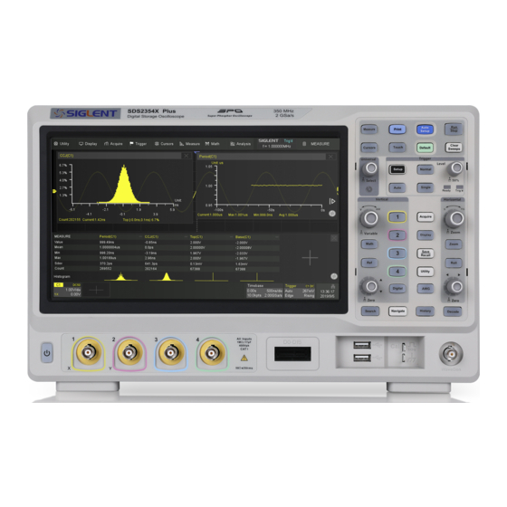
The SDS2000X series employs a new generation of SPO technology. It employs an innovative digital trigger system with high sensitivity and low jitter. The maximum waveform capture rate is 140,000 wfm/s (normal mode) and up to 500,000 wfm/s (sequence mode). - Page 10 Gating measurement, Math measurement, History measurement, Ref measurement Waveform math function (FFT, addition, subtraction, multiplication, division, integration, differentiation, square root) High Speed hardware-based Pass/ Fail function 25 MHz DDS arbitrary waveform generator - built-in 10 waveform functions (Optional) 4 SDS2000X Service Manual...
- Page 11 Large 8 inch TFT-LCD display with 800 * 480 resolution. Multiple interfaces, including USB Host, USB Device (USBTMC), LAN (VXI-11), Pass / Fail, Trigger Out Supports SCPI remote control commands Supports Multi-language display and embedded online help SDS2000X Service Manual 5...
-
Page 12: Prepare Information
Power-on Inspection The normal operating voltage for the SDS2000X series digital oscilloscope is in range of 100-240 VRMS ,50 Hz/ 60 Hz/ 440Hz. Connect the power cord to the socket on the rear panel of the oscilloscope. - Page 13 6 seconds simultaneously, until the boot screen appears. The oscilloscope will then begin to perform its power-on tests automatically, after which the DEFAULT SETUP button can be pressed in order to recall the factory default settings. SDS2000X Service Manual 7...
-
Page 14: Probe Compensation
Under Compensated Over Compensated Correctly Compensated 5. If the waveform does not show as “compensated correctly”, use a nonmetallic screwdriver to adjust the low-frequency compensation adjustment hole on the probe until the waveform displays correctly. 8 SDS2000X Service Manual... -
Page 15: Auto Setup
Recall the previous setup of oscilloscope (Undo Setup) The input signal frequency must be higher than 20 Hz, with the amplitude greater than 8 mV. Select the channel with the lowest frequency when several channels are connected to signals. SDS2000X Service Manual 9... -
Page 16: Self Calibration
4. When the self calibration process is completed, the following message will appear: “Press Run/Stop key to exit”. Press the Run/Stop button on the front panel to exit the calibration interface. Note: Under normal conditions the self-calibration procedure will take 10 SDS2000X Service Manual... - Page 17 SIGLENT approximately 20 seconds. If it does not complete within this period of time or it stops on one of the calibration settings, then there may be a problem with the instrument. SDS2000X Service Manual 11...
-
Page 18: Interface Test
SIGLENT Interface Test The SDS2000X series oscilloscope is designed with four standard interfaces: USB Host, USB Device, LAN and Pass/Fail. Connecting to other instruments via these interfaces enables the oscilloscope to achieve additional capabilities. In order to ensure the oscilloscope is operating properly it is recommended that the user first test the interfaces. -
Page 19: Usb Device Test
4. Click “Open VISA Test Panel” option button, and then the following Interface will appear. Next, click the “Input/Output” option button and click the “Query” option button in order to view the Read operation information. SDS2000X Service Manual 13... -
Page 20: Lan Port Test
1. Set up NI Max software in a computer and install the driver using the following instructions. 2. Press Utility Page2/3 LAN, input usable IP Address and Subnet Mask. Figure 4 IP Setting interface 3. Connect the oscilloscope to the computer using a LAN cable via the LAN interface ports. 14 SDS2000X Service Manual... - Page 21 NI software interface and select the “LAN” device symbol. 5. Click “Open VISA Test Panel” option button, which then displays the following interface (below). Then click the “Input/Output” option button and click the “Query” option button;. The Read operation information will be displayed. SDS2000X Service Manual 15...
-
Page 22: Pass/Fail Out Test
To test the Pass/Fail function and signal output by viewing on a second oscilloscope. Tools: A second oscilloscope Two BNC cables Steps: 1. Turn on the SDS2000X oscilloscope. 2. Enable Channel 1. 3. Press Utility Page2/3 Pass/Fail, set the submenu items under Pass/Fail menu as below:... - Page 23 SIGLENT After selecting the corresponding items as shown in the table above, the SDS2000X screen will appear as in Figure 6: Figure 6 Pass/Fail Waveform If the waveform is within the range that was set under Mask menu setting, the waveform displayed on the screen will Pass.
-
Page 24: Performance Test
BNC(m) to BNC(m), BNC Cables Approx.1m long DCG\Offset\Ext Trigger BNC T Connectors For signal distribution level Computer The figures below shows the interconnections between the test equipment and PC to the oscilloscope under test (Table 4): 18 SDS2000X Service Manual... - Page 25 SIGLENT Figure 8 Connecting test instruments for DCG\Offset Figure 9 Connecting test instruments for Clock/Trigger Delay Figure 10 Connecting test instruments for Ext Trigger Delay SDS2000X Service Manual 19...
- Page 26 Figure 11 Connecting test instruments for Ext Trigger Level Figure 12 Connecting test instruments for BW\BWL\Trigger Sensitivity\Input impedance SDS2000X SDM3055 C1 C2 C3 C4 计算机 BNC Cable Figure 13 Connecting test instruments for AWG Offset Accuracy 20 SDS2000X Service Manual...
- Page 27 SIGLENT SDS2000X C1 C2 C3 C4 计算机 BNC Cable Figure 14 Connecting test instruments for AWG Frequency Response SDS2000X Service Manual 21...
- Page 28 Self Calibration The Self Calibration procedure is described in Chapter " ". If the Self Calibration environmental temperature changes by more than 5℃, the Self Calibration operation must be performed in order to achieve the specifications. 22 SDS2000X Service Manual...
-
Page 29: To Verify Dc Gain Accuracy
1.5 V, 0.75 V,0,-0.75 V,-1.5 V 600 mV, 300 mV,0,-300 mV,-600 200 mV/div 300 mV,150 mV,0,-150 mV,-300 100 mV/div 50 mV/div 150 mV,75 mV,0,-75 mV,-150 mV 20 mV/div 60 mV,30 mV,0,-30 mV, -60 mV 10 mV/div 30 mV,150 mV,0,-150 mV,-30 mV SDS2000X Service Manual 23... - Page 30 SIGLENT 5 mV/div 15 mV,7.5 mV,0,-7.5 mV-15 mV 2 mV/div 6 mV, 3 mV,0,-3 mV, -6 mV 24 SDS2000X Service Manual...
-
Page 31: To Verify Offset Accuracy
500 mV/div 5 V,2.5 V,0,-2.5 V,-5 V 1.5% 200 mV/div 2 V,1 V,0,-1 V,-2 V 1.5% 100 mV/div 1 V,0.5 V,0,-0.5 V,-1 V 500 mV,250 mV,0,-250 mV,-500 1.5% 50 mV/div 1.5% 200 mV,100 mV,0,-100 mV,-200 20 mV/div SDS2000X Service Manual 25... - Page 32 SIGLENT 1.5% 10 mV/div 100 mV, 50 mV,0,- 50 mV,-100 mV 1.5% 5 mV/div 50 mV,25 mV,0,-25 mV-50 mV 2 mV/div 20 mV, 10 mV,0,-10 mV, -20 mV 1.5% 26 SDS2000X Service Manual...
-
Page 33: To Verify Time Base Accuracy
7. Press Measure button on the front panel of the oscilloscope to display Freq measurement. 8. Check if the Freq measurement is less than 1.2 kHz. 9. Disconnect the test connection. SDS2000X Service Manual 27... -
Page 34: To Verify Trigger Delay
5. Press Measure button on the front panel of the oscilloscope to display Time@Mid measurement. 6. Check if the result is in the limited range above. 7. Disconnect the test connection. 8. Check other channels in the same way as step 1 to step 7. 28 SDS2000X Service Manual... -
Page 35: To Verify Ext Trigger Delay
7. Press Measure button on the front panel of the oscilloscope to display Delay measurement. 8. Check if the delay is within the limited range above (<1 ns). 9. Disconnect the test connection. 10. Check the other analog channel in the same way as step 1 to 9. SDS2000X Service Manual 29... -
Page 36: To Verify Ext Trigger Level
9. Set the trigger slope to Falling, repeat step 6 to step 8. 10. Set amplitude of the 9500B to 2.6V, set trigger source of the oscilloscope to EXT/5, and the Volts/div to 350 mV. 11. Repeat step 5 to step 9. 12. Disconnect the test connection. 30 SDS2000X Service Manual... -
Page 37: To Verify Noise Floor
4. Check if the Stdev is in the limited range shown in Table 8. 5. Check the other analog channels in the same way as step 1 to 4. 6. Set the oscilloscope Volts/Div to the others in the table above, and repeat the steps from 3 to 5. SDS2000X Service Manual 31... -
Page 38: To Verify Bandwidth
1.2 V when testing at 200 mV/div. 9. Check other channels in the same way as steps 1 to 8. 10. Disconnect the test connection. After the test, calculate the dB value at every frequent point. Check if the value 32 SDS2000X Service Manual... - Page 39 Frequency Point (Hz) Range ≤10M (-1,1) dB SDS2104X/ ≤50M (-2,2) dB SDS2102X >50M (-3,2) dB ≤20M (-1,1) dB SDS2204X/ ≤100M (-2,2) dB SDS2202X >100M (-3,2) dB ≤30M (-1,1) dB SDS2304X/ ≤150M (-2,2) dB SDS2302X >150M (-3,2) dB SDS2000X Service Manual 33...
-
Page 40: To Verify Bandwidth Limit
10. Disconnect the test connection. After the test, calculate the dB value at every frequency point. Check if the value falls within the range in Table 12. Table 12 Limited Range Frequency Point(Hz) Range ≤19M (-2,2) >19M (-6,2) 34 SDS2000X Service Manual... -
Page 41: To Verify Trigger Sensitivity
2. Set amplitude of the 9500B to 200 mV, frequency to 10 MHz. 3. Set trigger source of the oscilloscope to EXT, trigger slope to Positive. 4. Press Trigger Level knob to set the level to the center of the waveform. SDS2000X Service Manual 35... - Page 42 15. Set the frequency of the 9500B to the oscilloscope‟s bandwidth frequency, amplitude to 1.5 V. Repeat steps 11 to 14.In step 6, the range changes to (-750 mV, - 750 mV) 16. Disconnect the test connection. 36 SDS2000X Service Manual...
-
Page 43: To Verify Input Impedance
When checking the EXT trigger channel, set impedance of the ext trigger channel to 50 Ω. Then record the reading displays on the screen of the 9500B, and check to verify it is within the specified range in Table 14. SDS2000X Service Manual 37... -
Page 44: To Verify Awg
SIGLENT To Verify AWG This test checks the Wave Generator option of oscilloscope, using a Siglent SDM3055 multimeter and an Agilent U2004A power meter. This test includes three items: Offset Accuracy, Amplitude Accuracy, and Frequency Response. Table 15 Offset Accuracy... - Page 45 9. Change the frequency, referring to Table 17, then record the reading on the U2004A to make certain it is within the specified range in Table 17. 10. Set amplitude of the waveform to 5 V, repeat step 9. 11. Disconnect the test connection SDS2000X Service Manual 39...
-
Page 46: Adjusting Procedures
SIGLENT Adjusting Procedures This chapter describes how to adjust the SDS2000X series oscilloscopes for optimum performance using a Fluke 9500B calibrator. Only qualified personnel should perform this procedure. Warming Up Before performing the adjustment procedures the oscilloscope and other test instruments must warm up for at least 30 minutes in an ambient temperature between 20 °... -
Page 47: Software Installation
2. Connect the oscilloscope with the PC using an USB cable. 3. Connect the SDM3055 with the PC using a network cable. 4. Connect the Agilent U2004A with the PC using an USB cable. Figure 15 DAC adjusting environment Figure 16 Clock Accuracy adjustment setup SDS2000X Service Manual 41... - Page 48 Figure 17 EXT Trigger Delay adjustment setup Figure 18 EXT Trigger Level adjustment setup SDS2000X SDM3055 C1 C2 C3 C4 计算机 BNC Cable Figure 19 AWG adjustment setup SDS2000X C1 C2 C3 C4 计算机 BNC Cable Figure 20 AWG adjustment setup 42 SDS2000X Service Manual...
- Page 49 SIGLENT 5. The details of the device IP address which are used in the setup are in the script titled devicecon.py in the path of SDS2000X\Lib. 6. Turn on the oscilloscope and allow it warm-up for about 30 minutes.. 7. Connect the oscilloscope and the test instruments as shown in the figures above using the BNC T connectors and BNC cables.
-
Page 50: Assembly Procedures
SIGLENT Assembly Procedures This chapter describes how to remove the major modules from the SDS2000X series oscilloscopes. To install the removed modules or replace new modules, please follow the corresponding operating steps in reverse order. This chapter includes the following topics: ... -
Page 51: Required Tools
Fan Module Keypad Module Display Module Required Tools Use these tools to remove or replace the modules in the oscilloscope: Multifunction screwdriver Antistatic gloves Custom screw hexagonal nut tool or long nose pliers SDS2000X Service Manual 45... -
Page 52: Disassembly Procedures
Remove each front-panel knob by firmly grasping the knob (with pliers protected by a soft cloth to prevent scratches, if necessary) and pulling it away from the front panel. To install the Front -Panel Knobs, please perform these steps in reverse order. 46 SDS2000X Service Manual... -
Page 53: Removing The Rear Panel
1. Place the oscilloscope face down on a soft surface such as an anti-static mat. 2. Remove the six screws located on the rear panel. In this same position, remove the four screws located on the tilt-legs.. 3. Lift the rear panel up and off carefully. SDS2000X Service Manual 47... - Page 54 SIGLENT To install the rear panel, please follow these same steps in reverse order. 48 SDS2000X Service Manual...
-
Page 55: Removing The Rear Metal Cover
5. The edge of the rear metal cover is sharp, please lift the rear metal cover up and off carefully to avoid personal injury. To install the rear metal cover, please perform these steps in reverse order. SDS2000X Service Manual 49... -
Page 56: Removing The Front Panel
1. Place the oscilloscope down on a soft surface such as an anti-static back-side mat. 2. Remove the eight screws located on the metal cover assembly. To install the front panel, please perform these steps in reverse order. 50 SDS2000X Service Manual... -
Page 57: Removing The Lcd, Channel Board And Keyboard
3. Remove the six screws located on the channel board. 4. Remove the seven screws located on the keyboard. 5. Disconnect the cable that connects the keyboard and the channel board. 6. Separate the modules carefully. SDS2000X Service Manual 51... -
Page 58: Removing The Main Board
3. Remove the ten screws located on the main board. 4. Separate the main board from the metal assembly and then lift it up and off carefully to avoid personal injury from the sharp edge of the metal 52 SDS2000X Service Manual... - Page 59 SIGLENT assembly. To install the main board, please perform these steps in reverse order. SDS2000X Service Manual 53...
-
Page 60: Troubleshooting Hardware Failures
Required Equipment The equipment listed in the table are required to troubleshoot the oscilloscope. Table 19 Required Equipment Equipment Critical Specifications Example Digital Multimeter Accuracy ±0.05% Agilent 34401A 1 mV resolution 54 SDS2000X Service Manual... -
Page 61: Main Board Drawing
11. CL63 Figure 27 TEST POINTS 15. T101 2. T90 10. T99 25. T102 7. T97 26. T103 21. T95 12. T94 16. T93 27. T89 28. T85 30. T84 17. T86 32. T91 13. T88 SDS2000X Service Manual 55... -
Page 62: Troubleshooting Flowchart
SIGLENT 24. T96 23. T98 22. T100 29. T87 30. T92 Figure 28 TEST POINTS (Continued) Troubleshooting Flowchart The following troubleshooting tree is recommended for quickly locating the defective subsystem or PCB. 56 SDS2000X Service Manual... - Page 63 SIGLENT Figure 29 Troubleshooting flowchart SDS2000X Service Manual 57...
-
Page 64: Check The Power Supply
If there is at least one voltage value out of the specified range then the power supply module is defective and will need to be replaced with a new one. For safety considerations, please do not disassemble the power supply module unless another person is present. 58 SDS2000X Service Manual... -
Page 65: Check The Main Board
VCC_1V8 1.81 ±5% VCC_-6V CL50 Pin2 -6.5 ±5% VEE_-5V T101 ±5% VCC_1V2 1.221 ±5% VCC_3V3 3.34 ±5% VLED(With CL2 Pin1 ±5% LCD) VLEDEE(With CL2 Pin2 ±5% VCC_6V5E U164 Pin3 ±5% VEA_A5V ±5% VCC_10V4 T100 10.32 ±5% SDS2000X Service Manual 59... -
Page 66: Check The Display Module
3. If the screen is abnormally bright, check the backlight and VGH, VGL first as described in step 1 and step 2. Then test the Clock signal pin, located on the main board. If the Clock signal is as specified, The problem may be due to a defective 60 SDS2000X Service Manual... - Page 67 Check if the rear USB cable is correctly correctly connected. interface working Check the LAN setting in the I/O set correctly menus, reboot the scope and try again. SDS2000X Service Manual 61...
- Page 68 SIGLENT Contact SIGLENT SIGLENT TECHNOLOGIES CO.,LTD Address:3/F, building NO.4, Antongda Industrial Zone, 3rd Liuxian Road, Bao‟an District, Shenzhen, P.R.China Tel:0086-755-3661 5186 E-mail:sales@siglent.com http://www.siglent.com 62 SDS2000X Service Manual...
Need help?
Do you have a question about the SDS2000X and is the answer not in the manual?
Questions and answers